INSTRUCTIONS FOR THE INSTALLER
INSTRUCTIONS FOR INSTALLATION OF THE APPLIANCE
(positioning and ventilation requirements)
The regulations covering the installation, maintenance and
operation of gas appliances for domestic use are applicable
regulations. An extract of these regulations appears below.
For all indications not covered, refer to the above mentioned
regulations.
POSITIONING:
(Fig. 2) the products of combustion from cooking appliances
must always be discharged into suitable extractor hoods,
which must be connected to a chimney, flue or vented directly
to outside the building. In situations where it is not possible to
install an extractor hood, an electric extractor fan installed in
a window or external wall may be used, provided that all
requirements of the ventilation regulations are satisfied; the
fan should switch on when ever the appliance is in
operation.VENTILATION:(Fig. 2) it is essential that the room
in which gas appliances are installed is adequately ventilated
to ensure that all the appliances receive the required quantity
of fresh air for combustion.To ensure an adequate airflow, it
may be necessary to create apertures in accordance with the
following requirements:
a)with cross-sectional area of 6 cm2 per kW with a minimum
cross sectional area of 100 cm2 (these apertures may also
be created by increasing the gap between the bottom of
doors and the floor);
b)situated at the bottom of an external wall, preferably
opposite the wall on which combustion products are
extracted ;
c)the positions of the apertures should selected so as to
avoid the possibility of their being obstructed and, if made in
external walls, they must be protected with grilles, metal
meshes, etc. installed on the outside face of the wall. If an
electric extractor fan for the removal of foul air is installed in
the room, the apertures provided for air changes must allow a
ventilation rate of at least 35m3/h per kW of power installed.
GAS CONNECTION
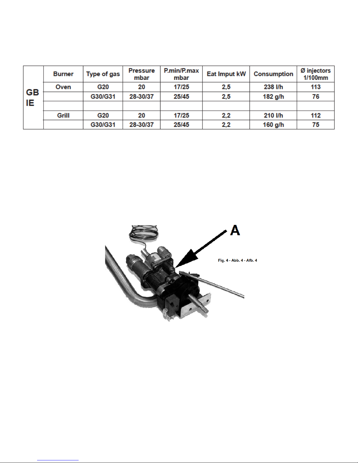
The oven is designed to operate with both natural gas (methane) and liquid gas (LPG), and can be
easily converted from one type to another following the instructions given in the relative section of
this booklet. Connection to the gas supply must be carried out by qualified technicians and in
conformance with the requirements.If the appliance is to operate with gas bottles (LPG), a
pressure regulator conforming to the requirements.
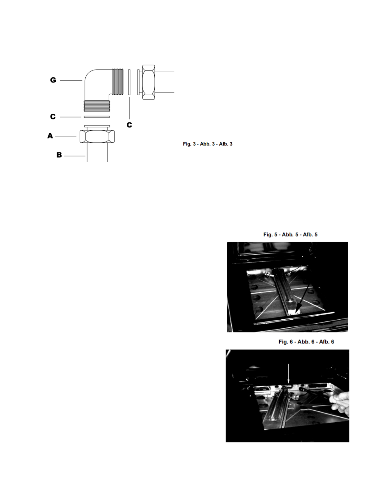
RIGID PIPE CONNECTION
Connection to the mains gas supply may be made via a rigid pipe firmly attached to the fitting
“G” (Fig. 3), or via a flexible stainless steel continuous wall hose,conforming with a maximum
length of 2 metres.The fitting “G” and seal “C” are supplied with the appliance,and comply with
standards.