ILX Lightwave LDT-5910 User manual

-~
ARTISAN
®
~I
TECHNOLOGY
GROUP
Your definitive source
for
quality
pre-owned
equipment.
Artisan Technology
Group
Full-service,
independent
repair
center
with
experienced
engineers
and
technicians
on staff.
We
buy
your
excess,
underutilized,
and
idle
equipment
along
with
credit
for
buybacks
and
trade-ins
.
Custom
engineering
so
your
equipment
works
exactly as
you
specify.
•
Critical
and
expedited
services
•
Leasing
/
Rentals/
Demos
• In
stock/
Ready-to-ship
•
!TAR-certified
secure
asset
solutions
Expert
team
ITrust
guarantee
I
100%
satisfaction
All
tr
ademarks,
br
a
nd
names, a
nd
br
a
nd
s a
pp
earing here
in
are
th
e property of
th
e
ir
r
es
pecti
ve
ow
ner
s.
Find the Newport / ILX Lightwave LDT-5910 at our website: Click HERE

INSTRUCTION hIANUAL
hIODEL LDT-5910
THERMOELECTRIC TEhIPERATURE CONTROLLER
ILX
Lightwave Corporation
34368 East Frontage Road
Bozeman, Montana,
U.S.A.
(406)
586-
1244
Artisan Technology Group - Quality Instrumentation ... Guaranteed | (888) 88-SOURCE | www.artisantg.com

WARRANTY
ILX LIGHTWAVE
CORPORATION
warrants this instrument to be frce from dcfccts
in material and workmanship for one year from the date of shipment. During
the warranty period we will repair or replace the unit, at our option, without
charge.
Limitation
This warranty does not apply to fuses, lamps, batteries, defects caused by abuse,
any modifications, or to use of the product for which it was not intended.
This warranty is in lieu of all other warranties, expressed or implied, including
any implied warranty of merchantability or fitness for any particular purpose.
ILX Lightwave Corporation shall not be liable for any incidental, special, or conse-
quential damages.
If a problem occurs, please notify
ILX
Lightwave Corporation and thoroughly
describe the nature of the problem and give the model and serial numbers. You
will be given prompt attention, service information, and return instructions.
Returning an Instrument
Before returning an instrument, obtain a return authorization number from the
factory. The instrument should be shipped in the original packing carton or one
that will provide equal protection. Shipping damage is not covered by this war-
ranty. Send the instrument, transportation pre-paid to the factory, referencing
the return authorization number. Repairs will be made and the instrument will
be returned, transportation pre-paid. Repairs are warranted for the remainder of
the original warranty or for
90
days, whichever is greater.
Claims for Shipping Damage
When you receive the instrument inspect it immediately for any damage or shortages
on the packing list. If the instrument is damaged immediately file a claim with
the carrier. The factory will supply you with a quotation for estimated costs of
repair. You must negotiate and settle with the carrier for the amount of damage.
Artisan Technology Group - Quality Instrumentation ... Guaranteed | (888) 88-SOURCE | www.artisantg.com

Table
of Contents
.................
CHAPTER 1
.
GENERAL INFORMATION
1
...........................
1.1 Introduction
1
........................
1.2 Product Overview
1
1.3 Specifications
?
-
..........................
................
1.4 Available Options and Accessories
3
........................
CHAPTER 2
.
OPERATION
4
2.1 Introduction
...........................
4
2.2 Installation
..........................
4
...................
2.3 AC Power Considerations 4
.....................
2.4 Tilt-Foot Adjustment
4
.......................
2.5 Rack Mounting 4
..................
2.6 LDT-5910 Front Panel Controls 4
2.7 Power
............................
6
......................
2.8 Main Control Knob
6
2.9 Auto
.............................
6
2.10 Actual Temp
.........................
6
2.11 Set Temp
...........................
6
2.12 Lock
.............................
6
2.13 Output On
..........................
7
2.14 GPIB Remote/Local Switch
..................
7
2.15 Parameter Set-Up
.........................
7
2.16 Select
............................
7
2.17 Set
.............................
7
2.18 Limit
............................
8
2.19 Gain
.............................
8
2.20 Calibration Constants
-
C1, C2 and C3
.............
8
2.21 Back Panel
............................
8
2.22 Back Panel Connections
...................
10
2.23 Grounding Considerations
...................
10
2.24 Current Switch
........................
10
2.25 Operating Instructions
......................
11
2.26 Warm Up and Environmental Considerations
..........
11
2.27 General Operating Procedure
................
11
CHAPTER 3
.
GPIB/IEEE-488 BUS CONTROL
...............
12
3.1 Introduction
...........................
12
3.2 Capabilities
...........................
12
3.2 Preparation for Bus Control
...................
12
3.3 An Overview of Remote Programming
...............
14
.........................
3.4 Command Set 14
3.5 Remote Programming Procedure
................
17
3.6 Input Syntax
.........................
17
3.7 Device Dependant Commands
...................
19
3.8 Data Entry Commands
....................
19
.....................
3.9 Sct Point Commands 19
3.10 Output Control Commands
..................
20
3.11 Lock Commands
.......................
20
Artisan Technology Group - Quality Instrumentation ... Guaranteed | (888) 88-SOURCE | www.artisantg.com

......................
3.12
Display Commands
2
1
........................
3.13 Get Commands
22
..........................
3.14
Put Values
23
....................
3.15 Terminator Commands
26
.......................
3.16 Clear Command
26
......................
3.1
7
Self Test Command
26
....................
3.18 Control Mode Command
27
.........................
3.19 Service Requests 28
............
3.20 The Serial Poll Register and the SRQ Mask 28
........................
3.21 Interface Messages
29
........................
3.22 Example Programs
30
.................
CHAPTER 4
.
THEORY OF OPERATION 32
...........................
4.1 Introduction 32
.......................
4.2 Power Supply Board 32
....................
4.3 Internal Power Supplies 32
...........................
4.4 MainBoard 33
...................
4.5 Constant Current Source 33
.........................
4.6 Input Buffer 34
.....................
4.7 Difference Amplifier 34
................
4.8 Digitally Controlled Gain Stage 34
4.9 Integrator
..........................
34
.....................
4.10 Summing Amplifier 34
.......................
4.11 Current Limiting 35
......................
4.12 Current Limit D/A 35
................
4.13 Current Limit Condition Sensing 35
4.14 Voltage Controlled Current Source ............... 35
4.15 Voltage Limit Condition Sensing
................
35
....................
4.16 Set Point Control D/A 35
4.17 Precision Voltage Reference
..................
36
4.18 A/D Convertor
........................
36
4.19 Microprocessor
........................
36
...........................
4.20 Memory 36
4.21 Serial Interface
........................
36
4.22 Latched Parallel 1/0 Port
...................
37
..........................
4.23 Display Board 37
4.24 Display Driver ........................ 37
4.25 Latched Parallel 1/0 Port
...................
37
.........................
4.26 LED Drivers 37
4.27 GPIB Interface Board ....................... 37
..................
4.28 Microprocessor and Memory 37
4.29 Optical Isolators
.......................
37
.......................
4.30 Serial Interface 37
4.3
1
GPIB Interface
.......................
38
CHAPTER 5
.
MAINTENANCE
......................
40
5.1 Overview ............................ 40
5.2 Calibration ............................ 40
...................
5.3 Recommended Equipment 40
5.4 Environmental Conditions
...................
40
5.5 Warm-up
...........................
40
5.6 Calibration Adjustments
.....................
41
Artisan Technology Group - Quality Instrumentation ... Guaranteed | (888) 88-SOURCE | www.artisantg.com

................
5.7
Manual Resistance Calibration
41
...............
5.8 Manual Current Limit Calibration
41
...........
5.9
Resistance Calibration Over the
GPIB
Bus
42
.........
5.10 Current Limit Calibration Over the GPIB Bus 42.
........................
5.1
1 Fuse Replacement
43
......................
5.12 Line Voltage Selection
43
...........................
5.13 Disassembly 43
CHAPTER 6
.
OPTIONAL MODEL 1227 GPIBIIEEE-488 INTERFACE
....
45
............................
6.1 Overview 45
..........................
6.2 Specifications 45
............................
6.3 Installation 46
.................
Appendix A
.
The Steinhart-Hart Equation 47
Appendix B
.
Sensing Current and Thermistor Selection
...........
57
.....................
Appendix C
.
Schematic Diagrams 60
List of Figures
2-1 LDT-5910 Front Panel Layout
...................
5
2-2 LDT-5910 Back Panel Layout
....................
9
........................
2-3 Back Panel Connector
10
3-1 Address Selection Switch Settings
.................
13
3-2 GPIB Remote Operation Diagram
.................
15
..............
4-
1 Functional Block Diagram of LDT-5910 33
4-2
Functional Block Diagram of 1227 Interface
............
39
5-1 AC Voltage Selection
.......................
44
A-1 Thermistor Resistance verses Temperature
.............
48
B-1 Thermistor Temperature Range
..................
58
Copyright.
1987.
ILX
Lightwave Corporation
Artisan Technology Group - Quality Instrumentation ... Guaranteed | (888) 88-SOURCE | www.artisantg.com

CHAPTER
1
GENERAL INFORhlATION
1.1
Introduction
This manual explains how to operate and maintain the LDT-5910 Thcrmoclcctric
Temperature Controller and optional model 1227 GPIBIIEEE-488 Intcrface. This
section gives a detailed overview of the LDT-5910. If you want to get started
using the LDT-5910 right away, skip to Chapter 2 (Operation).
1.2
Product Overview
The LDT-5910 is a microprocessor-based, precision thermoelectric temperature con-
troller designed for temperature control of laser diodes, dctcctors and other tcmpcr-
ature sensitive devices. The LDT-5910 can be used for laser diode testing, laser
diode frequency stabilization, IR detcctor cooling, and to dctermine the character-
istics of electronic devices. The LDT-5910 combines high analog stability with
the versatility of a microprocessor-based instrument. The internal microproccssor
controls the operation of the LDT-5910 and performs the non-linear conversion
of thermistor resistance to temperature based on three user defined constants.
You can configure the LDT-5910 to operate with a wide variety of thermistor
temperature sensors and TE modules. The model 1227 GPIB/IEEE-488 interface
allows remote programming and completely automated control of the LDT-5910.
Features of the LDT-5910 include:
Intuitive front panel layout
Large and easy-to-read green LED display
Display resolution of 0.1 degree Centigrade
Output current limit control to safely opcratc all TE coolers
Configurable for most thermistors
Output will supply
4.6
amps
Actual, Set and Auto display modes
Set temperature lock
GPIB/IEEE-488
interface available
Booster modules can be added to extend the output power
Artisan Technology Group - Quality Instrumentation ... Guaranteed | (888) 88-SOURCE | www.artisantg.com

Bipolar constant current source.
8
Volts at 1 A, 7 Volts at
2
A, 6 Volts at
3
A.
4.6
Amps.
15 Watts typical.
1.3
Specifications
Output
Output Type:
Compliance Voltage:
Maximum Current Output:
Maximum Output Power:
Current Limit Control Range:
Current Limit Accuracy:
Temperature Control
Temperature ~ange':
Resolution and ~ccuracy~:
Short Term stability3:
Scnsor Type:
Usable Resistance Range:
Sensing Current:
Calibration:
Display
Display Type:
Maximum Reading:
Resolution:
General
Power Requirements:
Size:
Temperature Range:
Warmup:
-50 "Cto >lo0"C with typical 10
K
thermistor
Temperature Resolution Accuracy
0°C kO.1 "C k0.2
"
C
20°C 20.1 "C k0.2
"
C
50 "C f0.2 "C k0.2
"
C
0.01 "C or better.
2-wire thermistor.
0 to 450
K
ohm typical.
10 uA or 100 uA (user sclcctable).
Thermistors are calibrated by storing three con-
stants of the Steinhart-Hart equation, listed
below, in internal non-volatile memory.
l/~=(Cl*lO-~)+(C2*10-~)(ln
~)+(~3*10-~)(lnR)~.
4
digit green LED display.
9999 mA, 999.9
"
C.
kl.O mA, kO.1 "C.
105-125 or 210-250 VAC(jumper sel
ectable) 50-60 Hz.
88
mm
x
212 mm
x
269 mm (3.5" x
8.4"
x 10.6").
Operating: 0 to 50
"
C, Storage: -40 to 70
"
C.
1 hour
to
rated accuracy.
1.
Temperature control range depends primarily on the type of thermistor and TE module used. The range can be
extended higher and lower by selecting appropriate components. See Appendix B for more details.
2.
Accuracy figures quoted are typical for a 10
K
ohm thermistor and 100 uA source current setting. Accuracy figures
are relative to calibration standard. Both resolution and accuracy are dependent on the user defined configuration
of the instrument.
3.
Short term temperature stability is a strong function of the thermal environment of the thermistor and TE module.
Room air currents in particular can easily cause fluctuations of 0.1
C
in an exposed mounting configuration.
Artisan Technology Group - Quality Instrumentation ... Guaranteed | (888) 88-SOURCE | www.artisantg.com

1.4
Available Options and Accessories
The
following options and accessories are available for
the
LDT-5910.
DESCRIPTION MODEL
NUMBER
GPIB/IEEE-488 interface 1227
Output power booster module 5310
Rack mount flange kit 302
Rack mount, 1/2 width
filler panel kit
Enclosure interlocking kit 112
The 1227 interface permits GPIB bus control of the LDT-5910 for automated test
and measurement applications. Chapter
6
describes this option in detail.
The LDT-5910 enclosure can be rack mounted by itself or interlocked with other
ILX Lightwave, X-series instruments. The accessories listed above are for rack
mounting and interlocking these instruments.
1.5
Your Comments
ILX Lightwave Corporation is committed to making the best laser diode instrumenta-
tion available anywhere. To serve you best, we need your ideas and comments on
ways we can improve our products. We invite you to contact us at any time with
your suggestions.
Artisan Technology Group - Quality Instrumentation ... Guaranteed | (888) 88-SOURCE | www.artisantg.com

CHAPTER
2
OPERATION
2.1 Introduction
This chapter describes how to install, program and operate the LDT-5910. It is
divided into five sections covering installation, front pancl controls, proccdurcs
for programming the LIMIT, GAIN and constants
C1,
C2, and
C3,
the back pancl
connections, and normal operating procedures.
2.2 Installation
2.3
AC Power Considerations
You can configure the LDT-5910 to operate at line voltages from 105 to 125 VAC
or 210 to 250 VAC. Before using the LDT-5910 check that the voltage printed
on the rear panel matches the power-line voltage supplied in your area. If it is
necessary to reconfigure the input voltage range refer to chapter 5 (Maintenance).
WARNING
To avoid electrical shock hazard, connect the instrument only to
properly earth-grounded, 3-prong receptacles. Failure to observe
this precaution can result in injury or loss of life.
2.4
Tilt-Foot Adjustment
The LDT-5910 has front legs that extend to make it easier to view the LED display
To use them, place the LDT-5910 on a stable base and rotate the legs downward
until they lock into position.
2.5 Rack Mounting
The LDT-5910 may be rack mounted by installing a rack mount flange on one
side of the enclosure and a half width filler panel on the other side. Alternately,
two X-series enclosures will interlock side-by-side, with a pair of rack mount
flanges, for rack mounting as one unit. All rack mount accessory kits contain
detailed mounting instructions. Refer to Section 1.4 for applicable rack mount
accessory part numbers.
2.6
LDT-5910
Front Panel Controls
The following sections describe the front panel controls on the LDT-5910. Gen-
erally these controls are simple to operate. The setup parameters, however, are
intentionally a bit awkward to use so that their values are not inadvertently
changed. Figure 2-1 shows the LDT-5910 front panel and its controls.
Artisan Technology Group - Quality Instrumentation ... Guaranteed | (888) 88-SOURCE | www.artisantg.com

DISPLAY
POWER
OFFION
SWITCH
GPIBIIEEE-488
REMOTE MODE
INDICATOR AND
LOCAL SWITCH
DISPLAY MODE SWITCHES
AND
INDICATORS
TEMPERATURE LOCK MODE
SWITCH AND INDICATOR
MAIN CONTROL KNOB
LIMITCURRENT
DISPLAY INDICATOR
THERMISTOR CONSTANTS
DISPLAY INDICATORS
OUTPUT
OFFION
SWITCH
PARAMETER SET
SELECTOR SWITCH
PARAMETER DISPLAY
SELECTOR SWITCH
FEEDBACK LOOP GAIN
DISPLAY INDICATOR
FIGURE
2-1
LDT-5910 FRONT PANEL LAYOUT
Artisan Technology Group - Quality Instrumentation ... Guaranteed | (888) 88-SOURCE | www.artisantg.com

2.7
Power
With the LDT-5910 connected to an
AC
power source, pressing the Power off/on
switch will supply power to the instrument and start the power-up sequence.
All
the front panel LEDs will light. After approximately threc scconds the display
will read the actual temperature in degrees centigrade and the instrument
will
bc
in Auto mode.
2.8
Main Control Knob
The main control knob is a precision ten turn potentiometer that adjusts the
instrument set temperature. This knob is also used to change the instrument sct
point temperature setup parameters. Turning this knob to the right increases
the value on the display.
2.9 Auto
When in Auto mode the display shows the actual thermistor temperature until
you turn the main control knob. The LDT-5910 senses that you have turned thc
knob and "knows" that you want to input a new set temperature. The instrument
displays the new set point temperature for three seconds and then rcturns to
displaying the actual temperature. The Auto mode allows you to accurately change
the set point temperature and quickly see how your device is responding. The
Auto button has a toggling action; press it to enter auto mode and press it again
to exit auto mode.
2.10 Actual Temp
When this button is pressed the LDT-5910 displays the actual thermistor temperature
and the LED on the button lights to indicate that the actual temperature is dis-
played.
2.11 Set Temp
This button, when pressed, displays the temperature set point and the LED on
the button lights to indicate that the set tempcrature is
displayed.
Turn the
main control knob to enter a new set point.
2.12 Lock
When you press the front panel LOCK button the LDT-5910 stores the current
set temperature in memory and disables the main control knob. The LED lights
to show that the unit is in lock mode. The value stays in memory even if the
LDT-5910 is shut off. If you use the same set point temperature day after day
you will appreciate the LDT-5910 LOCK feature. To release the LDT-5910 from
lock mode, press the lock button again.
Caution
Turn the output off before releasing the unit from lock mode.
If the main control knob position has changed the LDT-5910 will
read the new knob position and try to control the temperature
to that setting.
Artisan Technology Group - Quality Instrumentation ... Guaranteed | (888) 88-SOURCE | www.artisantg.com

2.13
Output On
This button switches the output of the LDT-5910 on. The off/on button has a
toggling action. If the output is off, pressing it will turn the output on and vice
versa. The LED above the indicator button lights when the output is active.
When the output is off it is safe to connect or remove sensitive devices from
the LDT-5910 even though power is on. The output is off when power is first
applied to the instrument.
The output off/on button also indicates when a thermal limit condition occurs.
In
the rare event that excessive heating occurs in the LDT-5910 output stage (or in
an attached booster module) the output of the LDT-5910 is turned off and thc
output off/on LED flashes. The output automatically turns back on when the
output stage cools down.
2.14
GPIB Remote/Local Switch
This button returns the instrument to local control when it is in remote mode with
the optional Model 1227 GPIB/IEEE-488 interface installed. Any command sent
to the LDT-5910 via the GPIB bus automatically places the instrument in remote
mode and the REMOTE LED lights. All the front panel controls, except power
and GPIB REMOTE/LOCAL, are disabled and will only operate remotely. Pressing
the LOCAL button will return the instrument to local mode and all the front
panel controls will operate.
If no command has been sent over the GPIB bus, the LDT-5910 is in LOCAL mode
and its address will be displayed when you press this button. If the instrument
is in remote mode and a local lockout (LLO) mcssage has bccn sent, the host has
complete control of the LDT-5910 and the LOCAL button has no effect. For
more information on GPIB programming, read chapter
3.
2.15
Parameter Set-Up
2.16
Select
The select function displays the setup parameters so you can review or change
their values to configure the LDT-5910 for your thermistor and TE cooler. Press
the SELECT button and the limit will be displayed until you release the button.
The value will show for three seconds before the LDT-5910 returns its previous
state. Press the Select button again to sequence the display through GAIN, C1,
C2 and C3. The sections below describe each of these values and how to change
them.
2.17
Set
This button, along with the main control knob, is used to change the setup par-
ameters: LIMIT, GAIN, C1, C2 and C3. Sequence to the setup parameter you
wish to change and hold the SELECT button in to continuously display this value.
Simultaneously press and hold in the SET button. Now turn the main control
knob until the new value is displayed. Release the Set button to store the par-
ameter in non-volatile memory. The instrument will automatically go into lock
mode to save the present set point when the SET button is pushed.
Artisan Technology Group - Quality Instrumentation ... Guaranteed | (888) 88-SOURCE | www.artisantg.com

2.18
Limit
The limit function limits the output current so that the LDT-5910 does not provide
more current than your device can safely handle. To rcad the limit, press the
select button until the LED by the LIMIT is lit and the display will show the
value of the
LIMIT
(in mA). To change the limit, sequence
to
thc LIMIT value
and hold in the SELECT and the SET button. Turn the main control knob until
the new value is on the display and then release the SET button. The LIMIT
should be entered in milliamperes, e.g., 1 amp would be entercd as 1000 mA.
The LDT-5910 will supply as much current as it can, up to a current limit set
point of 4600 mA, to control the temperature as quickly as possible. The LDT-5910
can supply up to 10 A with the optional power booster module installed.
The LIMIT LED also indicates two special conditions, current and voltage limiting.
If the output is current limited, as when the output is first turned on, the LIMIT
LED will flash slowly
(2
times/second). If the output is voltage limited, if for
instance no load is connected, the LIMIT LED will flash faster (4 times/second).
2.19 Gain
The gain function sets the analog feedback gain which determines how fast the
actual temperature reaches and settles to the set point temperature. If the gain
is set too low the TE cooler will take longer to reach the temperature set-point.
If it is set too high the actual temperature will overshoot and may cycle around
the set temperature. The gain setting depends on the type of TE cooler that
you are using, but we can give guidelines for selecting the proper gain. Set the
gain to its lowest value and increase it until the actual tempcrature oscillates
around the set temperature. Then reduce the gain one increment. To set the gain,
sequence to the GAIN value and hold in the SELECT and the SET button. Turn
the main control knob until the new value is displayed and then release the SET
button. The feedback loop gain can be selected in increments of
1,
3, 10, 30,
100 and 300.
2.20 Calibration Constants
-
C1, C2 and C3
These are the constants of Steinhart-Hart equation that you enter to calibrate
the LDT-5910 for different thermistors. Appendix A contains an explanation of
the Steinhart-Hart equation, the values of these constants for some common ther-
mistors and a computer program to determine these values for any thermistor.
To read a constant press the SELECT button until it sequences to C1, C2 or C3.
The LED next to the constant will light. To change the value, press the SELECT
and the SET buttons and turn the main control knob until the correct number is
displayed. Release the SET button to store the new value in non-volatile memory.
2.21 Back Panel
The back panel contains the thermistor input,
TE
module output, AC power entry
connector, fuse, and a thermistor source current set switch. When the optional
model 1227 GPIBIIEEE-488 interface is installed, the back panel additionally contains
the standard GPIB bus connector and the GPIB address selector switch. The
back panel is shown in figure 2-2.
Artisan Technology Group - Quality Instrumentation ... Guaranteed | (888) 88-SOURCE | www.artisantg.com

THERMISTUR
INPUT
GPIB
BUS
CONNECTOR
TE MODULE THERMISTOR
OUTPUT SOURCE CURRENT
SET SWITCH
GPIB
ADDRESS
SELECTOR SWITCH
AUXILIARY
INPUT/UUTPUT
CUNNECTOR
FUSE
POWER
ENTRY
CONNECTOR
I
Artisan Technology Group - Quality Instrumentation ... Guaranteed | (888) 88-SOURCE | www.artisantg.com

2.25
Operating Instructions
2.26
Warm
Up
and Environmental Considerations
Operate the LDT-5910 at an ambient temperature between 0 and 50 degrees centi-
grade. Storage temperatures should be in the range
-40
to
70
C.
To
achieve
the rated accuracy let the LDT-5910 warm up for about
1
hour before use.
2.27
General Operating Procedure
You can operate the LDT-5910 in several modes. The following operating procedure
is applicable for most common use.
a. Plug the LDT-5910 into an AC power source supplying the correct voltage
and frequency for your unit (refer to the rear panel for the correct
ratings).
b. Turn on the LDT-5910. The output stage will be off at power-up.
c. Check the setting of the GAIN, LIMIT and C1, C2, and C3 to insure that
they are compatible with the equipment you are using. Refer to sections
2.15 to 2.20 if you need to change them.
d. Press the Set Temp button and check the set point temperature. If it
requires changing refer to the section above.
e. Turn the output on by pressing the output on button
f.
The LDT-5910 will automatically control the temperature to the set point.
Artisan Technology Group - Quality Instrumentation ... Guaranteed | (888) 88-SOURCE | www.artisantg.com

CHAPTER
3
GPIBIIEEE-488 BUS
CONTROL
3.1
Introduction
When the model 1227 GPIB/IEEE-488 intcrface is installed and the instrumcnt
is
connected to a host computer, the LDT-5910 can be used as an automated tcmper-
ature controller and temperature recorder for test measurement applications.
3.2
Capabilities
The model 1227 GPIB/IEEE-488 interface allows GPIB/IEEE-488 bus control of the
LDT-5910. All of the features accessible from the front panel and some advanced
features can be accessed via the interface bus. Information can also be read by
the host computer and printed or stored. Other features include:
A concise and simple command set
Full talk/listen capability
Full serial poll capability, with bit-maskable SRQ
Selectable output terminators
Full local/remote capability including LOCAL LOCKOUT
Resistance Control Mode controls to a set
resistance
Support for the following interface messages: REN, DCL,LLO, GTL and
SDC
3.2
Preparation
for
Bus Control
To use the LDT-5910 remotely, you will need to install an IEEE-488 interface
adapter in your host computer. These adapters and support software are avail-
able from several manufacturers and can be installed in most computers. This
manual assumes that you have a basic knowledge of the GPIB/IEEE-488 interface
bus and how to use it for instrument control. This section also assumes that
you are familiar with the controls on the LDT-5910. Read Chapter
2
again if
you need more details on how to operate the LDT-5910.
Install the 1227 interface using the procedure outlined in Chapter
6.
Prepare the
LDT-5910 for bus control using the following procedure:
1.
Turn off the power to the LDT-5910/1227 and set the GPIB/IEEE-488
interface address with the DIP switches on the back panel. The switch
settings are shown in figure 3-1. You can choose any address for the
LDT-591011227 but this address should be unique, i.e., different than any
other instrument connected to the bus.
Artisan Technology Group - Quality Instrumentation ... Guaranteed | (888) 88-SOURCE | www.artisantg.com

Switch Positions
Address
1
2
3
4
5
Switch Positions
Address
1
2
3
4
5
00001
10001
01001
11001
00101
10101
01101
11101
00011
10011
01011
11011
00111
10111
01111
-Not Allowed-
FIGURE
3-1
ADDRESS SELECTION SWITCH SETTINGS
Artisan Technology Group - Quality Instrumentation ... Guaranteed | (888) 88-SOURCE | www.artisantg.com

2.
Plug
the
GPIBIIEEE-488
bus cable into the LDT-5910/1227 rear panel
connector and secure it with the plug-mounted screws.
3. Turn on the LDT-591011227 and press the local button to display the
selected IEEE-488 instrument address on the front panel display.
3.3
An Overview of Remote Programming
The block diagram, figure 3-2 shows the flow of data from the LDT-5910/1227 to
the host computer (the controller). Each block represents a register, buffer etc,
contained in the LDT-5910. The input buffer receives data from the IEEE-488
bus. The output buffer receives data from the blocks to its left and sends data
to the IEEE-488 bus. The serial poll register is a separate buffer that gets the
attention of the controller in special conditions.
Information is transferred between blocks by device dependant commands. For
example, a Put command takes a number from the input buffer and stores it in
the internal memory of the LDT-5910. Likewise the Get command gets the con-
tents of the LDT-5910 internal memory and copies it into the output buffer.
Programming commands, like print and read in BASIC or FORTRAN, transfer the
information from the input or output buffers to the controller. The following
simple program provides an example of how the LDT-5910 is controlled by the
host computer. The exact programming statements you will need to use will depend
-
on the programming language and IEEE-488 interface card that you are using. This
program instructs the LDT-5910 to display actual thermistor temperatures and
then reads out the current display. The LDT-5910 is assumed to be at GPIB
-
address
1.
100 Print @1:"D2"
110 Input @l:A$
120 Print
A$
130 End
-
3.4
Command Set
There are two types of commands that you can use with the LDT-5910/1227 and
-
the GPIB bus. Messages that only the LDT-5910/1227 understands are called
device dependant commands. Messages that are common to any instrument on
the GPIB bus are called interface messages. The device dependant commands are
summarized in Table
3.1
and described in sections 3.7 to 3.17. The LDT-5910/1227
-
also responds to a number of interface messages to participate in IEEE-488 bus
communication. The interface messages are summarized in Table 3.5.
Artisan Technology Group - Quality Instrumentation ... Guaranteed | (888) 88-SOURCE | www.artisantg.com

MICROPRUCESSOR MEMORY
SET POINT Tnnnmnn
TEMPERATURE
v
A
Rnnnmnn
RESISTANCE
--
A
GO
-
e
3
SRQ
REGISTER
SET-UP PERAMETERS
G1
,
P1
I
DISPLAY
CURRENT LIMIT
G2
,
P2
GAIN
G3
,
P3
C1
7
A
G4
,
P4
C2
V
G5
,
P5
INSTRUMENT MUDE
CUNTROL
INPUT
BUFFER
--
-
-
DO
,
01 OUTPUT CONTROL
LO
,
L1 LOCK CUNTROL
DO
-
D5
DISPLAY MODE
WO
-
W5
OUTPUT TERMINATOR CUNTRUL
ZO
,
n
SELF TEST
,
CLEAR
YO
-
Y2 REMOTE/LOCAL MODE CUNTRUL
FIGURE
3-2
GPlB REMOTE OPERATION DIAGRAM
C3
CALIBRATION PERAMETERS G6
,
P6
CAL-RlO
w
A
G7
,
P7
CAL-R100
3,
CAL-CL OUTPUT
BUFFER
G9
,
P9
USER DEFINED MESSAGE
Artisan Technology Group - Quality Instrumentation ... Guaranteed | (888) 88-SOURCE | www.artisantg.com
Table of contents
Other ILX Lightwave Temperature Controllers manuals
ILX Lightwave
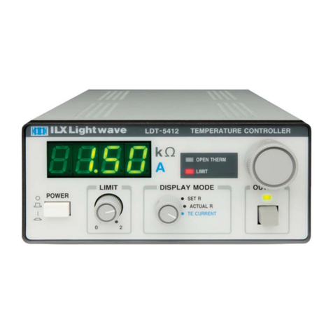
ILX Lightwave LDT-5412 User manual
ILX Lightwave
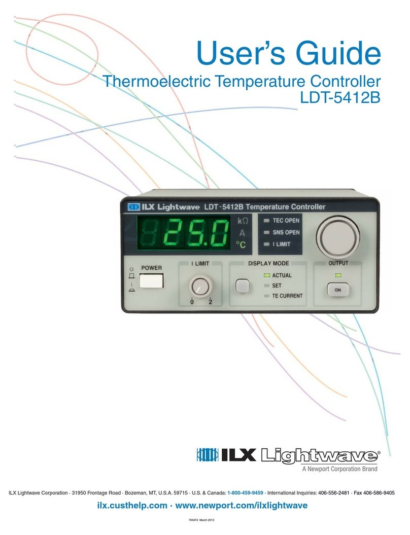
ILX Lightwave LDT-5412B User manual
ILX Lightwave
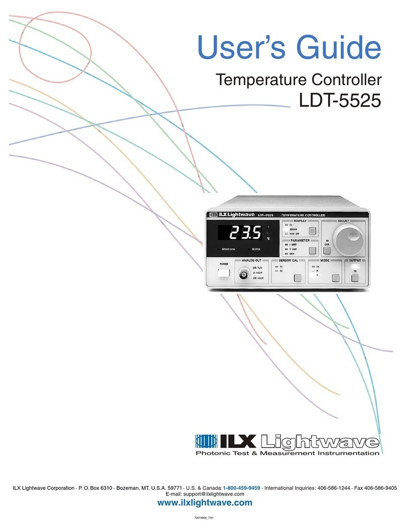
ILX Lightwave LDT-5525 User manual
ILX Lightwave
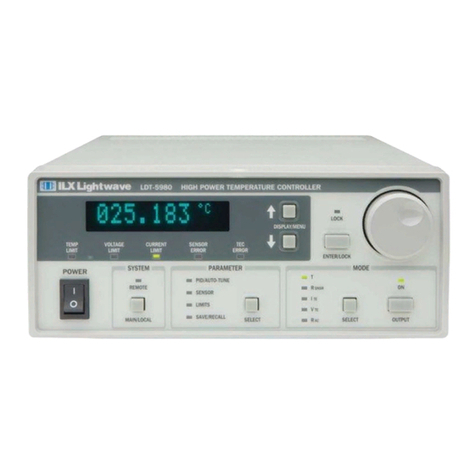
ILX Lightwave LDT-5900 Series User manual
ILX Lightwave
ILX Lightwave LDT-5500B Series User manual
ILX Lightwave
ILX Lightwave LDT-5416 User manual
ILX Lightwave
ILX Lightwave LDT-5525 User manual
