iM3 Revolution 4DC-Mobile User manual
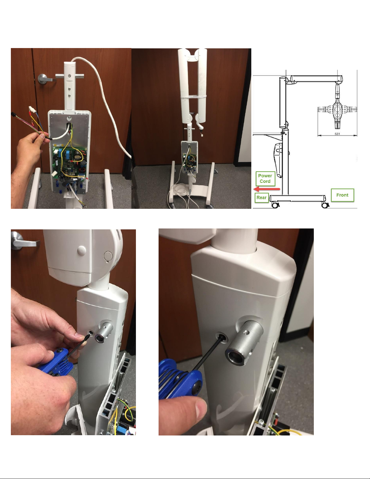
iM3 Revolution 4DC- Mobile Installation Manual
iM3 Revolution 4DC- Mobile Installation Manual, version 4.5
IT Tech Support Team:Alan Fennell Jeremy Moran
iM3 Inc. –The Veterinary Dental Company
12414 NE 95th ST, Vancouver, WA 98682
Office Hours: M-F 7am-5pm PST.
Office Phone: 1-800-664-6348 IT Tech Support Line: 1-844-838-3092
For after hour support, please call IT Tech Support line.
Email: afennell@im3usa.com JMoran@im3usa.com
Revolution 4DC- Mobile
Installation Manual

iM3 Revolution 4DC- Mobile Installation Manual
iM3 Revolution 4DC- Mobile Installation Manual, version 4.5
Revision History
Date
Version
Author
Description
9/11/17
2.1
Alan Fennell
Add Warning Labels
9/19/17
2.2
Alan Fennell
Add Remote Sync Instructions
9/20/17
2.3
Jeremy Moran
Update Base instructions, wiring
for power connector, securing
remote to wall mount
9/22/17
3.0
Alan Fennell
Base and Scissor arm orientation
3/14/18
4.0
Alan Fennell
Update Contact Info. Add new
remote image. Update base
instructions. Add new image of
Revolution.
4/6/18
4.1
Alan Fennell
Update White 3pin Scissor Arm
Molex connector note. Pg 13, 14.
4/11/18
4.2
Alan Fennell
Update Attaching Generator
Head Instructions, P. 17
7/9/18
4.3
Alan Fennell
Update to Step 10. P. 20, Added
Step 11: Check for Arm Drift. P.
20. Added Step 12: Check tube
head rotation. P. 20. Added Step
13: Calibration Test. P.20. Added
Appendix 1-4. P. 24-29
7/12/18
4.4
Jeremy Moran
Update to Step 6: Added Main
Board layout description. Added
Step to include how to change
WiFi Channel. Added Appendix 5.
10/18/19
4.5
Alan Fennell
Updated
Title/Footer/Header/Index.
Update to Step 12. Added tube
head/scissor arm
functionality/performance test.
Updated Actuator adjustment
instructions. Updated Office
Hours.

iM3 Revolution 4DC- Mobile Installation Manual
iM3 Revolution 4DC- Mobile Installation Manual, version 4.5
Index
Page 1 Tools, Hardware and Parts Required
Page 4 Step1- Assembling the Base
Page 5 Step 2- Locking Casters
Page 6 Step 3- Attaching Stand to Base
Page 8 Step 4- Mounting Control Board and Scissor Arm
Page 12 Step 5- Mounting Handles to Stand
Page 13 Step 6- Connecting Ground and Power Connectors
Page 16 Step 7- Securing Power Cord and Cover
Page 17 Step 8- Attaching Generator Head and Collimator
Page 20 Step 9- Application of Warning Labels
Page 21 Step 10- Test Fire Generator/Check Remote Sync
Page 21 Step 11- Correcting E301/E302 Error codes
Page 21 Step 12- Tube Head/Scissor Arm Functionality/Performance Test
Page 21 Step 13- Calibration Test
Page 22 Additional Information: Remote Wall Mount Instructions, Powering Generator
Page 23 Using the Revolution 4DC
Page 24 Revolution 4DC Remote Control Tutorial
Page 25 Appendix 1- Resync Remote to Tube Head
Page 26 Appendix 2- Correcting Arm Drift
Page 28 Appendix 3- Adjusting Actuator Assembly
Page 30 Appendix 4- Conducting Calibration Test
Page 31 Appendix 5- Changing WiFi Channel on Remote Control

iM3 Revolution 4DC- Mobile Installation Manual
1
Tools, Hardware, and Parts Required:
1. Tools
2.5mm Allen Wrench
3mm Allen Wrench
4mm Allen Wrench
5mm Allen Wrench
6mm Allen Wrench
Flat Head Jeweler Screwdriver
#2 Phillips Screwdriver
2. Hardware- Note: Please inventory hardware bag prior to installation.
A. Tube Head Covers
B. Cover Flaps (3)
C. Remote Mount
D. Stand Handles (2)
E. Retaining Pin
F. Dog Head Set Screws
(2)
G. Long 8mm Allen
Wrench
H. Stand and Base Bolts (8)
I. Dog Head Plugs (2)
J. Zip Ties (2)
K. Set Screw Plug
L. Control Board Mounting
Screws (4)
M. Handle Screws (2)
N. Remote Mount Screws
(2)
O. Dry wall anchors (2)
P. Moving Caution Stickers (2)
Q. Tube Head Screws w/
washers (2)
R. Set Screw
S. Friction Element
T. Curved Spring Washers (4)
U. Scissor arm Brass ring
V. Remote Mount
Washers (2)

iM3 Revolution 4DC- Mobile Installation Manual
2
3. Parts. Note: Please inventory parts prior to installation. (Stand Cap will be in hardware package).
A. Stand Cap
B. Base Assembly
C. Control Board
D. Control Board Cover
E. Stand
F. Scissor Arm
G. Tube head w/
collimator
H. Remote

iM3 Revolution 4DC- Mobile Installation Manual
3
Parts Cont.

iM3 Revolution 4DC- Mobile Installation Manual
4
Step 1- Assembling the Base
Prior to Installation of this step: See bottom right image for proper alignment of base plate to legs.
Tools required: 6mm Allen Wrench
Hardware required: 6 Base and Stand Bolts (Hardware- H).
Parts required: Base plate and caster legs (Parts- B)
Description: Remove base components from box and 6 base bolts. With caster side of legs facing up, insert base plate with
counter sunk holes on base plate facing up and match concave arch pattern of base plate with legs so that legs are angled
outwards.
1a 1b

iM3 Revolution 4DC- Mobile Installation Manual
5
Step 2- Locking Casters
Tools required: None
Hardware required: None
Parts required: None
Description: Once base is assembled, flip the base back over with casters down and lock casters.

iM3 Revolution 4DC- Mobile Installation Manual
6
Step 3- Attaching Stand to Base
Tools required: 6mm Allen Wrench
Hardware required: Retaining pin (Hardware-E) and 2 bolts (Hardware-H ), Scissor arm Brass Ring (Hardware-U)
Parts required: Stand with Power cable (Parts- E), Assembled base, Stand Cap (Parts- A). Styrofoam Top and Bottom Piece from
Stand Box.
Description: With 6mm Allen wrench, two bolts, retainer pin, and foam box (top and bottom), lay stand on foam box (3a). Slide
retainer pin in bottom of stand (3b-3c). Using one of the bolts, screw bolt in retaining pin slightly so that you can align retaining
pin better (3d). Once aligned, remove and slide both bolts through bottom of base. Screw both bolts in to retainer pin as shown
(3f). Place Scissor arm brass ring and stand cap on stand (3h).
Note:Powercable on stand faces towards rear of base assembly when complete (3e).
3a 3b
3c 3d
3e

iM3 Revolution 4DC- Mobile Installation Manual
7
3f 3g
3h

iM3 Revolution 4DC- Mobile Installation Manual
8
Step 4-Mounting Control Board and Scissor Arm
Tools required: 3mm Allen Wrench, 4mm Allen Wrench, 5mm Allen Wrench, Flathead Jeweler screwdriver
Hardware required: Control board mounting screws (Hardware- L), Friction Element (Hardware- S) with Curved Spring
Washers (Hardware- T), Set Screw (Hardware –R), and dog head set screws (Hardware-F).
Parts required: Control Board (Parts- C) and Scissor Arms w/ Power cable (Parts-F),
Description:
1. Slide stand power cable through bottom opening of control board (4a) and secure board to stand plate with lock-
tight screws as shown with 4mm Allen Wrench (4b-4c).
2. While keeping scissor arm velcroed together, carefully feed scissor arm power cable through top opening of stand
through to top opening of control board as shown (4d-4h).
3. Tube connector end of scissor arm should face towards front of stand once seated.
4. Screw in dog head set screws with 3mm Allen wrench on each side of stand as shown until it stops, then back out
½ turn (4j-4k).
5. Place curved spring washers back to back on friction element as shown (4l). Place friction element on set screw.
Carefully screw in set screw w/ friction element half way with 5mm Allen wrench, in screw hole on top of stand.
Adjust friction element with flat head screwdriver to align vertically so that the curve of friction element is flush
with the base of scissor arm. Once met, screw in the rest of the set screw until desired tension is met. (4l-4o)
: Do not release Velcro strap on scissor arm until the end of Step 7. Injury
may result.
4a 4b 4c

iM3 Revolution 4DC- Mobile Installation Manual
9
4d 4e 4f
4g

iM3 Revolution 4DC- Mobile Installation Manual
10
4h 4i
4j 4k

iM3 Revolution 4DC- Mobile Installation Manual
11
4l ----
4m 4n 4o

iM3 Revolution 4DC- Mobile Installation Manual
12
Step 5- Mounting the Handles to Stand
Tools required: 2.5 mm Allen Wrench
Hardware required: Handle screws (Hardware- M), Handles (Hardware-D)
Parts required: None
Description:
1. Slide hollow end of handles over mounting bars so that the contoured end is facing back.
Note: One handle goes up and the other goes down.
2. Secure handles with screws as shown (5a-5b)
5a 5b

iM3 Revolution 4DC- Mobile Installation Manual
13
Step 6- Connecting ground and power ports
Tools required: Flat head Jeweler screwdriver. #2 Phillips Screwdriver
Hardware required: None
Parts required: None
Description:
Grounding- Connect ground cables as shown making sure that grounding wires are faced towards center of mounting
plate.
1. Secure the two larger yellow and green grounding wires on right grounding port with Philips head screwdriver.
2. Secure the small yellow and green and black grounding cables to the left grounding port with Phillips head
screwdriver (6a).
Power- Connect black, white, and green power connectors to circuit board.
3. Connect black 6pin male power connector from scissor arm to black 6pin female port on circuit board as shown
(6b).
4. Connect white 3pin male power connector from scissor arm to white 3pin female port on circuit board (6c).
5. Remove green connector on bottom right of circuit board. Push in (From left to right), Left (Live Wire), Middle
(Ground), Right (Neutral) cables from stand power cable to green connector. Secure with flathead retaining
screws using flat head jeweler screwdriver on green connector. Once secured, plug in green connector to
corresponding port on circuit board (6d-6f). Note: Measure at wall outlet for live wire.
6a

iM3 Revolution 4DC- Mobile Installation Manual
14
6b 6c
Note: When connecting this connector (6c), it is ok if wires connect Blue to Blue and Brown to Brown, or Blue to
Brown and Brown to Blue as shown below.

iM3 Revolution 4DC- Mobile Installation Manual
15
6d 6e 6f

iM3 Revolution 4DC- Mobile Installation Manual
16
Revolution Main motherboard layout fully assembled:
Port No.
Description
K1
Ignition switch connection
K2
Mains power supply (From left to right: Brown, Yellow/Green, Blue)
K3
Contact for external lamp (max 2A- clean contact)
K4
External emission button
K5
Arm cable (head)
K6
Arm cable (power)
K15
Wired remote connection port: 1 PIN Red, 2 PIN White/Brown, 3 PIN Blue
K18
Interlock contact with blue jumper
F2
Main Fuse: 230-240 Vac -> 8A; 115-120 Vac -> 12A
J2
115Vac Only Contact with Red Jumper

iM3 Revolution 4DC- Mobile Installation Manual
17
Step 7 –Securing Power Cord and Cover
Tools required: #2 Phillips Screw driver
Hardware required: 4” Zip tie (Hardware-J), Cover Flaps (Hardware-B)
Parts required: Control cover (Parts-D)
Description:
1. Thread zip tie to blue tie anchor on circuit board plate. Coil power cable. Secure cable with zip tie as shown (7a).
2. Place bottom end of cover underneath power switch and align with control board and push slightly (7b).
3. Secure plastic retainer tabs with screws using Philips screwdriver. Once secured, gently secure flaps and close (7c).
Note: Cover Flaps are very fragile.
7a
7b 7c--->
Table of contents
Other iM3 Dental Equipment manuals
Popular Dental Equipment manuals by other brands

Aseptico
Aseptico ADU-07A ECONO AIR SYSTEM Operation & instruction manual

EMS
EMS AIRFLOW Prophylaxis Master quick guide

Air Techniques
Air Techniques ProVecta 3D Prime operating instructions

Dentsply Sirona
Dentsply Sirona ProPex II user manual

W&H
W&H Endea Endo Cursor EB-62 Instructions for use

Instrumentarium
Instrumentarium Orthopantomograph OP200 D user manual