iM3 Endo-A-class Vet LED User manual

FOR VETERINARY USE ONLY
iM3 Endo-A-class Vet LED
INSTRUCTIONS FOR USE AND
TECHNICAL MANUAL
Endo-A-class Vet LED

1. Product Overview
2. Safety Precautions Before Using
3. Product Components
4. Component Name and Function
5. Operation
6. Error Messages
7. Maintenance and Repair
8. Cleaning, Disinfection and Sterilization
9. Troubleshooting
10. Product Specifications
11. Warranty
12. Product Disposal
13. Electrical Specification
p2
p3
p4
p5
p5
p10
p11
p11
p13
p14
p15
p15
p16
※You have required to read this manual carefully before operating this machine.
Contents
1-
-
-
-
-
-
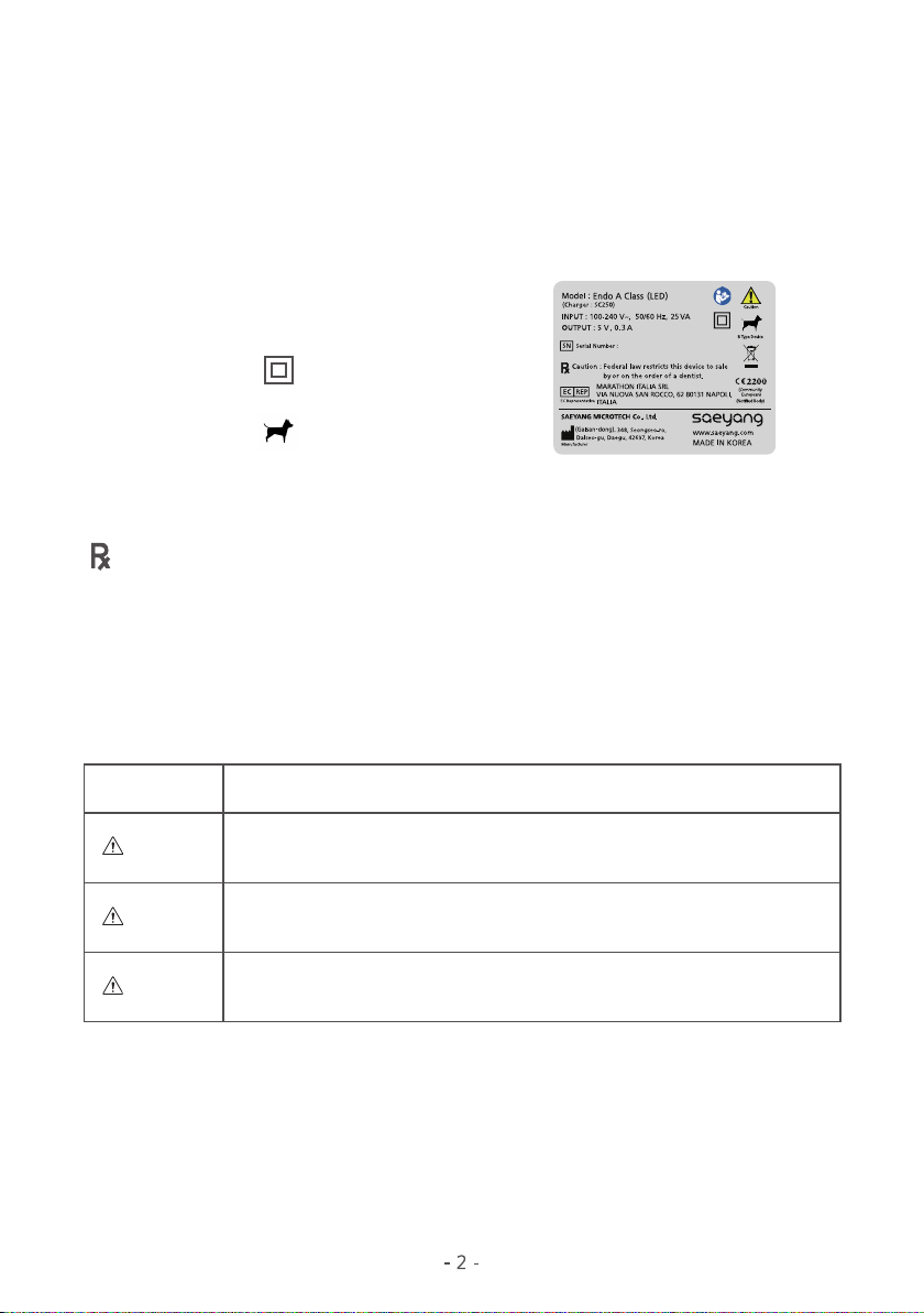
2. About the unit
Protection rating against electric shock
: Class Ⅱ equipment
Protection type against electric shock
: Type B applied part
Ordinary equipment (IPX0)
Not suitable for use in the presence of a flammable anesthetic mixture with air, oxygen or nitric oxide.
Continuous operation.
- Indicates instructions to be observed for safety.
- Indicates a potentiallyt hazardous situation which could result in minor or
moderate injury or damage to the device
- Indicates a potentially hazardous situation which could result in serious injury or
damage to the device.
- For safety, read and understand “Safety Precautions” thoroughly before use.
- Not only will these precautions help you use the product safely, but they will prevent harm you
and to others. They are classified according to degree of danger, damage or seriousness.
Classification Degree of Danger, Damage and Seriousness
Danger
Warning
Attention
Product Overview
1. Indications for Use
−This equipment is veterinary device
−Common name - Dental controllers for contra angle handpiece
This application area extends to endodontic prodedures using a root canal instrument which
is intended by the manufacturer for use in the mechanical and rotary preparation of root
canals.
1-3. Precautions for Safe Handling and Operating
Caution : Federal law restricts this device to sale by or on the order of a dentist
Attention
2. Safety Precautions Before Using
Danger
Warning
- The system may be subject to malfunction when used in the presence of electromagnetic interference.
- Do not locate the system in the vicinity of other devices that possibly emit electormagnetic interference.
- Do not disassemble the dental handpiece charger and dental handpiece.
- Before cleaning the product, be sure to turn off the power and then wipe the dental handpiece with a dry
cloth.
- Do not use any organic solvent to clean dental handpiece and dental handpiece charger.
- For the follow up service and spare parts, please contact your local dealer.
- Ensure that the product is not exposed to dust, sulfur or salt.
- Use the recommended files only.
- Endo A Class (LED) Motor is designed for use by veterinary professionals only.
- Special care must be taken to maintain patient safety while in use.
- Read this user’s manual thoroughly and understand functions of individual components completely.
- Make sure the product is in good working condition prior to use. If there is no any abnormal condition,
continue to use the product.
- Before using the product, the test run must be performed to check if the product is working normally.
- If there is any abnormal condition, including excessive vibration, noise and heat while using the product,
immediately turn off the power to stop using and contact your local dealer for repair.
- Electric motors generate significantly more power than traditional air turbines and air motors.
- Poorly maintained, worn, damaged, or misused handpieces may generate frictional heat capable of causing
serious burn injuries to the patient.
- Handpieces must be properly maintainded according ro the specified maintenance schedule and inspected
for signs of wear prior th each use.
-To prevent personal injury or product damage, it is required ro check if the dental handpiece has been
turned off before changing the file.
- Violent shocks, such as dropping the product, may cause product damage.
-Transport and storage conditions. The product must be transported and stored at temperature of -20~40℃,
atmosphere pressure of 700~1060hpa, and humidity if 0% to 90%, If the conditions are not satisfied,
the product may not work normally.
- This product was designed so that the maximum temperature of the product during charging and operation
does not exceed 40 degrees, and so that there is no thermal injury to the human body.
If abnormal heating phenomenon is occured during charging or operation, stop using it immediately and
contact your where to buy or manufacturer.

Dental Handpiece
Contra Angle
Optic led ass’y
Spray Nozzle
- Do not use or leave the product in high-temperature environment such as under strong direct sunlight,
in a car under a blazing sun, by fire or near stove.
- Check the product before use, pay attentions to looseness, vibration, noise and temperature(heat generation).
If any abnormal condition is found even slightly at that time, immediately stop use and contact your dealer.
- Always clean the shank of the file to be installed. Allowing dirt to enter the chuck could cause loss of
concentricity and deterioration of chuking force.
- Do not lubricate the dental handpiece. Only lubricate the head and shank.
- Do not heat sterilize the dental handpiece. Do not autoclave the dental handpiece.
LED cap
Dental Handpiece Charger
Power Cord
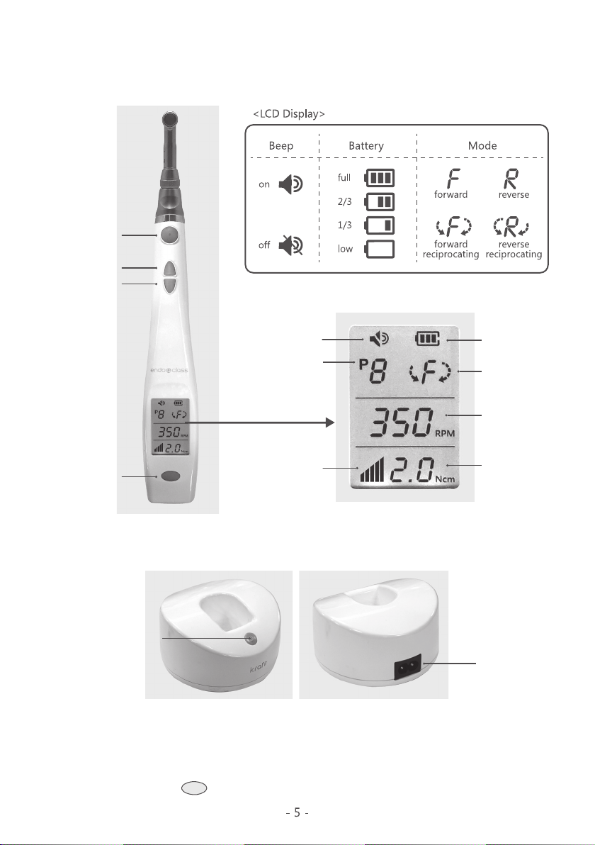
4-2. Dental Handpiece Charger
5-1. Buttons
5. Operation
4. Component Name and Function
4-1. Dental Handpiece
1) Power & Select Buttons
Power Inlet
Up Button
Power On/off Button
(Power LED & Charging LED)
Motor On/Off Button
Down Button
Power & Select Button
Program No.
Battery
Mode
Beep
Speed
Torque Level Torque
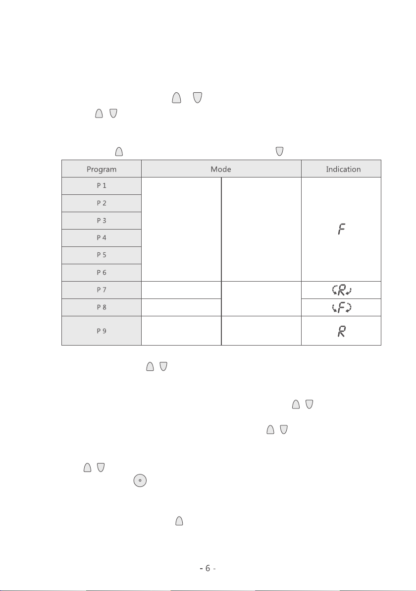
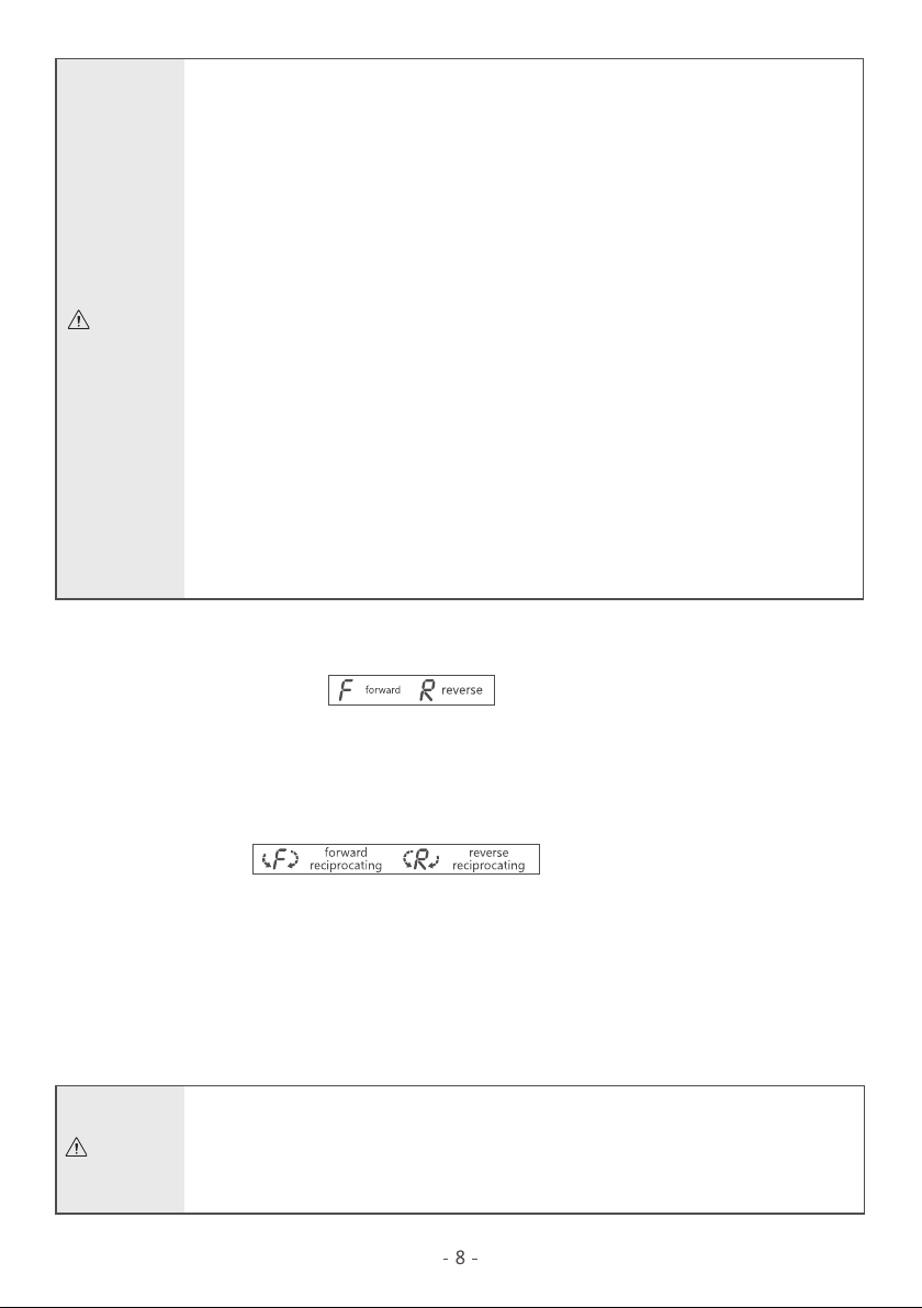
Standard
(Forward Direction)
Standard
(Reverse Direction)
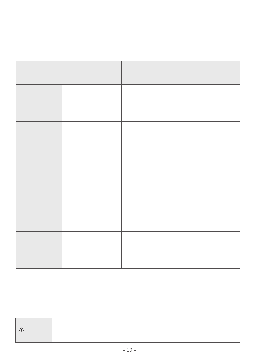
Reverse Reciprocating
Forward Reciprocating
Auto Stop Reverse
Auto Stop Reverse
# By pressing / button, each mode change as below.
① Program
-From 1 to 9, total 9 programs are repeated.
When pressing “ “ button, its number increase and pressing “ “ button, its number decrease.
②RPM
- 150 to 1000 by pressing / button, in each step 50 of increase or decrease appears, as follows
150, 200, 250, 300, 350, 400, 450, 500, 550, 600, 650, 700, 750, 800, 850, 900, 950 and 1000
③Torque
- In case of standard and reverse mode, from 0.5 to 3.0, by pressing / button, in each
step 0.5 of increase or decrease appears, so it rotates as follows 0.5, 1.0, 1.5, 2.0, 2.5, 3.0.
- In case of Reciprocating mode, from 2.0 to 7.0, by pressing / button, in each step 0.5 of
increase or decrease appears, so it rotates as follows 2.0, 2.5, 3.0, 3.5, 4.0, 4.5, 5.0, 5.5, 6.0, 6.5, 7.0.
④Buzzer
- When / button is pressed, buzzer signal is on/off repeatedly
- This switch is used to run motor and stop it.
- When it is the case optic LED, only you could ON/OFF when the motor is operated.
When operated motor you press button and you can choose between ON/OFF options.
- During operation, in case of loading, bar graph indicates its actual torque.
2) Increment / Decrement Button, / Button
- To turn it off, press and hold the switch for longer than 2 second when the power is on.
- To turn it on, press and hold the switch for longer than 2 second when the power is off.
- When press the switch shorter than 1 second, selection mode is activated with flickering on LCD
display. Selection mode appears in the following order, program, rpm, torque, beep, auto reverse
and program repeatedly.
3) Motor on / off button
4) Others
Auto Stop

5-2. How to Charge Battery
#The battery must be fully charged according to the following instructions.
1) First of all, check if the voltage shown on the product corresponds to the local main
power supply voltage before connecting to the power supply(the input power of
Endo A Class(LED) is 100~240VAC).
2) Surely insert the power cord into the power connector at the rear of the dental
handpiece charger and then connect the power cord to a power inlet.
3) After turning on the power button ( press the button more than 0.5 seconds), make sure
that charging LED turns green.
4) Put the handpiece into the dental handpiece charger to charge before the first use(when
the handpiece is put into the dental handpiece chatger, the charging LED is changed to
yellow from green to indicate the unit is in charge. With a buzzer sound at the same time
the handpiece is put, the handpiece LCD is turned on to show the battery charge level).
5) When the battery is fully charged, LCD back lights from the handpiece will be turns off
and the charge level signs will all be appeared.(When fully charged, separated the
handpiece from the charger, the LCD back light will turn on.)
· If there is no a buzzer sound or LCD is not turned on even after the handpiece is put
into the charging stand, immediately stop using the unit and contact your near local
dealer or service center for repair.
·When the charging LED is not turned on even after the power button Is turned on,
there must be surely a problem in the dental handpiece charger circuit.
In that case, contact your local dealer or service center for repair.
·Inserting the power cord or pressing the power button too strongly may result in
damage to the power connector, button or circuit, to which careful attention must be
paid.
Attention
5-3. Operation Modes
·Do not use the unit from other manufacturers with the dental handpiece charger of
Endo A Class (LED),and do not put substances, such as metal pieces, cable or liquid,
into the dental handpiece charger because they may result in damage to the circuit
or overheating and catching fire.
·While the battery is in dental handpiece charger, there may be a likelihood of over-
heating at the rear of the handpiece, but the overheating is slight and transient and
thus does not have any problem.If the handpiece is continuously put into and removed
from the dental handpiece charger for a short time, it will not be fully charged
with some overheat on the rear case.
Once the handpiece is put into the dental handpiece charger, therefore, do not remove
the handpiece from the dental handpiece charger until it is fully charged.
·The completely drained battery can not bedental handpiece charger, so it must be
replaced with the new battery.
·Avoid charging the battery in the location being exposed to an excessively high level
of temperature change(under direct sunlight, near the window or heater).
·Install the dental handpiece charger in the area where the change in temperature is
slight, in addition to less humidity.
·The battery will not be dental handpiece charger when :
Battery is fully dental handpiece charger. / Battery is damaged.
·Surely use only Endo A Class(LED)'s own dental handpiece charger to charge the
handpiece.
·To turn the power off,unplug the power sord from the power inlet
and the electricity will run out.
Attention
# Endo A Class (LED) can be set to operate in the following two modes.
1) Auto Stop Reverse mode
- When the dental handpiece is overloaded, it stops running immediately and runs in reserve
direction until the overload is solved. After the overload is solved, the handpiece starts and
run again in forward direction.
-During reverse mode when the dental handpiece is overloaded, it stops running
immediately and runs in forward direction until the overload is solved. After the overload
is solved, the handpiece starts and runs again in reverse direction.
2) Auto Stop mode
- During reciprocating mode, when the dental handpiece is overloaded, it stops running.
# Remark
-Auto stop reverse is available only for Forward mode & Reverse mode
- Auto stop is available only for Forward Reciprocating mode & Reverse Reciprocating mode
-Forward reciprocating operation stands for movement characterized by repeatable back-
and-forth motion and runs in forward direction.
-Reverse reciprocating operations stands for movement characterized by repeatable back-
and-forth motion and runs in reverse direction.
·In case of a low battery voltage, actual torque can not come up to its setting torque
and please use it after charging the battery sufficiently.
·During reciprocation mode, it may occur overheating caused by repeatable back-and-
forth motion. In order to reduce its temperature,please use it again after keeping in a
cool place for a while.
Attention

5-4. Contra Angle connection and disconnection
5-5. How to Insert and Remove the File(Push Type)
· The contra angle attachment must be replaced surely after turning off the power.
· Do not use any contra angle attachment from other manufacturers with this unit.
· Check if the contra angle attachment is surely connected to the dental handpiece
before operation.
Attention
1) Lightly turn and insert the file into the chuck while pressing and holding the button.
2) Make sure the file is properly inserted into the chuck by lightly pulling the file while not pressing the
button.
3) Remove the file while pressing the button.
Attention
· Surley turn off the power to insert and remove the file.
· After inserting the file, check if it is properly inserted into the chuck by lightly
pulling it by hand.
· Always clean the contact point of the file before insertion.If it is not inserted
properly due to dirt, clean and insert the file again.
· Use the file within the file's recommended speed limit.
# Remark
-When the LED is not used, it is recommended to block by the LED cap.
5-6. How to connect and disconnect the LED attachment
LED cap
Optic led ass’y
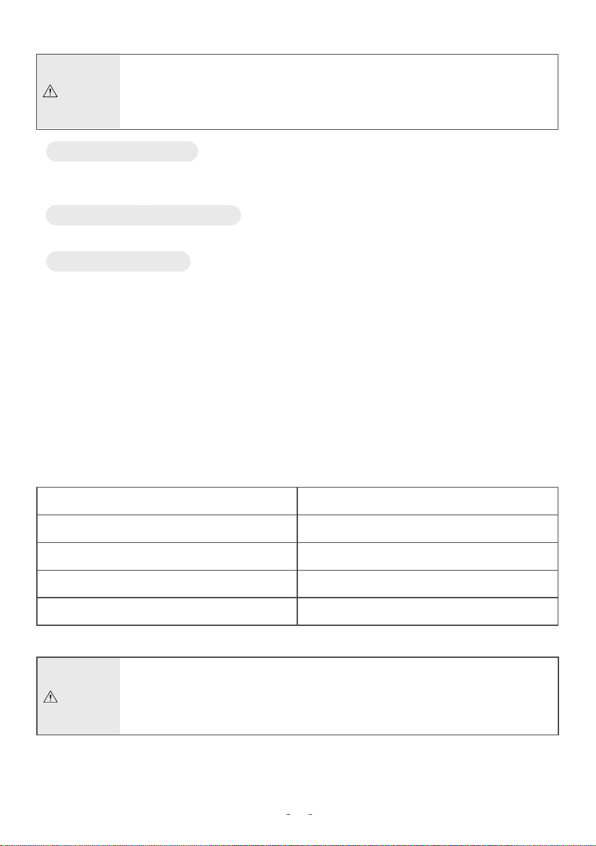
· Every error message is cleared by pressing the motor on/off switch, and the unit then
returns to standby mode.
· Contact the local
service center for
repair.
· Battery problems would
be assumed.
· Battery problems would
be assumed.
· When the circuit part is
damaged.
· Check if the angle
portion is locked.
· Increase the preset
torque value.
· Replace the battery.
· Contact the local
service center for
repair.
· Replace the battery.
· Contact the local
service center for
repair.
· Replace the battery.
·The preset torque is
exceeded.
# The following error messages displayed on the LCD will help you easily find out the cause
of errors.
· Battery voltage is
excessively high.
·Battery voltage is too
high while charging.
· Motor driver circuit is
defective
·Battery voltage is too
low while charging.
6. Error Messages
Attention
· When the dental
handpiece is locked.
· When the load exceeding
the preset torque is
imposed.
· When battery type is
different.
· When the circuit is
defective.
Error Code
E1
E2
E4
E5
E7
Error Cause Solution

8. Cleaning, Disinfection and Sterilization
7-1. Lubricating the Contra Angle
7. Maintenance and Repair
· Do not use a spray can upside down. In such case only spray gas comes out instead of
oil.
· To prevent attachment flying off from a spray nozzle-hold it securely.
1) Lubricate once a day before sterilization.
2) Screw the spray nozzle onto the spray can for approximately 10 turns.
3) Insert the spray nozzle into the rear part of the contra angle attachment and lubricate
until oil comes out from the attachment head which is approximately 2~3 seconds.
4) Attachments should be vertically positioned so all extra oil will drain out then wipe off
outside surfaces.
# Only the contra angle attachment of Endo A Class(LED) is allowed to be lubricated.
# The lubrication is needed after each use and before sterilization.
- Do not use chloride detergent materials.
- For your own safety, please wear personal protective equipment to include, but not limited to gloves,
glasses,and masks.
- Do not sterilize the dental handpiece, the dental handpiece charger,or the AC cable.
After each use, all the objects that were in contact with infectious agents should be cleaned using
towels impregnated with a disinfection and detergent solution.
General Recommendations
# For hygiene and sanitary safety purposes, the contra-angle attachments must be cleaned
disinfected, and sterilized before each usage to prevent any contamination.
This concerns the first use, as well as subsequent uses.
Attention
Attention ·
Do not autoclave or steam sterilize dental handpiece
12
· The contra angle must be steam sterilized prior to initial use and between patients to
prevent cross contamination. After sterilization, make sure the contra angle attachment
has reached a temperature below 40℃ before use.
Cleaning Dental Handpiece Charger
- When the charger becomes dirty, wipe it off with a cotton cloth moistened with surgical spirit.
Cleaning Dental Handpiece
-When the dental handpiece becomes dirty, wipe it off with a cotton cloth moistened with rubbing
alcohol.
Cycle
Configuration
Temperature
Exposure Time
Dry Time
·It is recommended that the micro-dental handpiece be protected against cross-
contamination using a disposable barrier sleeve.
·The device consists the durability of at least 250 sterilization cycles.
wrap
132℃(=270℉)
4 minutes
20 to 30 minutes
Pre-vacuum
Attention
Autoclaving Contra Angle
- Only the contra angle attachment of Endo A Class(LED) is allowed to be sterilized. It is recommended
to sterilize the contra angle using the autoclave during or after treatment, according to the following
procedures.
① Clean the contra angle using a soft brush and then wipe out the dirt on its surface with a soft
cloth(do not use a metal wire brush).
② Lubricate the contra angle as specified in above Article 7-1.
③ Put the contra angle into the autoclave.
④ Set the temperature of the autoclave(for example, about 4 minutes at 132℃(=270℉).
⑤ After the contra angle is sterilized using the autoclave,it has to be dried and kept in a clean place.
(20 to 30 minutes drying time is recommended)
Attention
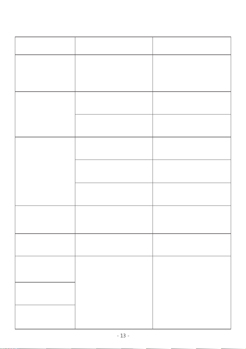
·LCD does not turn on.
·When the battery is completely
drained.
·When the power cord is not
connected to a power inlet.
·If the battery was not completely
drained, it must be charged
again.
·Replace the battery in
compartment.
·Surely connect the power cord to
a power inlet.
·Check the error message.
·Turn on the power switch.
·Contact your near dealer.
·Contact your local dealer for
repair.
·Clean the contra angle or replace
with a new contra angle.
·Charge the battery.
· When the battery or the circuit
of the dental handpiece is
defective.
·When the power switch is turned
off.
·When the fuse is cut.
·When dust comes into contra
angle.
·When the remaining voltage in
the battery is too low.
·When an error code is displayed.
· When the battery was completely
drained.
· When the dental handpiece was
not used for a long time.
·Battery is not charged
properly.
·Battery dental handpiece
charger is not working
(the dental handpiece
charger’s LED is not
turned on).
·Dental handpiece loaded
on the dental handpiece
charger is overheated.
·The power of the motor
handpiece is unusually
weak.
·The RPM of the motor
handpiece is unusually
reduced.
·Dental handpiece is not
rotating.
·Auto Reverse function is
not working.
9. Troubleshooting
Problem Cause Solution
Rechargeable Battery
Main Voltage
Rated Capacity
Dimensions(W*D*H)
Weight
Gear Ratio
Max. Speed(RPM)
Operative Speed
Type of Connector & Chuck
Weight
Dimensions(Φ*L)
1:1
1000
150-1000
SMT’s own connector type & Push type chuck
30g
15.5*87.0
Li-ion
3.7V
800mAH
29.9*32.9*157.1
130g
Main Voltage
Rated Capacity
Dimensions(W*D*H)
Weight
100-240V AC, 50/60Hz
300mA
100.0*100.0*49.4
150g
Dental Handpiece ChargerDental Handpiece
Contra Angle
Use Environment
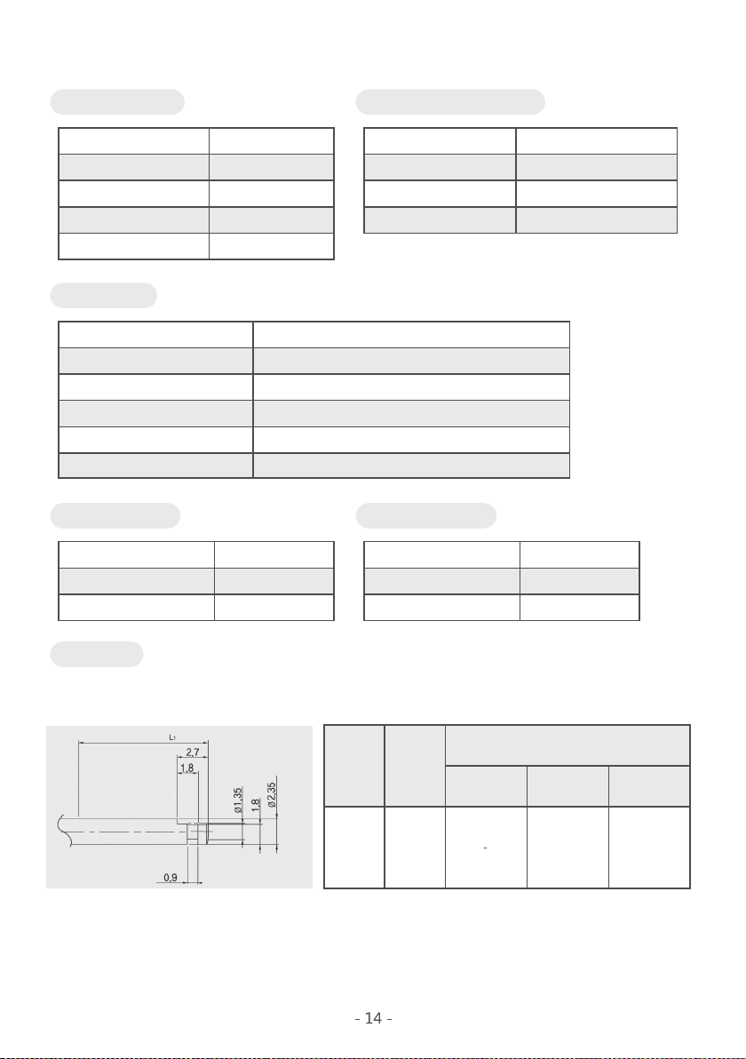
Shank Type
# The start of any enlargement on a TYPE 1 shank(e, g, by marking or the working head) shall be
outside L1=13.5mm.
Type 1 (ISO1797-1)
Fitting length, L1
Shank
a
Type1 2.35 11 12
Diameter
Miniature, shot Standard, long Extra long
Temperature
Humidity
Atmospheric Pressure
10 ~ 35℃
10 - 75%
700 - 1060hpa
Store Environment
Temperature
Humidity
Atmospheric Pressure
-20 ~ 40℃
0 - 90%
700 - 1060hpa
10. Product Specifications

11. Warranty
- All items of this unit are guaranteed for 12 months from the date of purchase.
- This guarantee expressly excludes any consequential failure or damage caused by neglect
handling, incorrect fitting and misuse.
12. Product Disposal
12-1.Disposal of the Endo A Class(LED)(control unit)and Dental handpiece
charger
- Follow your country-specific law, directives, standards and guidelines for the disposal
of used electrical devices.
12-2. Disposal of the packaging material
- All packaging material have been selected according to environmentally compatible and
disposal aspects and can be recycled. Please send old packaging materials to the relevant
collection and reprocessing system.In this way, you will contribute to the recycling of raw
materials, and the avoidance of waste.
15
Electromagnetic emissions
Emissions test
RF emissions
CISPR 11
RF emissions
CISPR 11
Harmonic emissions
IEC 61000-3-2
Voltage fluctuations/
flicker emissions
IEC 61000-3-3
Compliance
Group 1
Class A
Class A
Complies
Electromagnetic environment
The Endo A Class(LED) model device uses RF energy only for
its internal function. Therefore, its RF missions are very low
and are not likely to cause any interference in nearby
electronic equipment.
The Endo A Class(LED) model device is suitable for use in all
establishments, including domestic establishments and those
directly connected to the public low-voltage power supply
network that supplies buildings used for domestic purposes.
The Endo A Class(LED) model device is intended for use in the electromagnetic environment specified below.
The customer or the user of the Endo A Class(LED) model device should assure that it is used in such
an environment.
16
13. Electrical Specification
- The unit meets the collateral standards of electromagnetic compatibility - Requirements and
tests EN 60601-1:2007(IEC 60601-1-2) the limits and methods of measurements of electromagnetic
disturbance characteristics of industrial, scientific and medical radio frequency equipment
EN 55011 Group 1, Class A, medical electrical equipment is subject in regard to the electromagnetic
compatibility(EMC) and its special precautionary measure.
- The unit must in reference to the mentioned EMC-hints in the accompanying documents be
installed and operated. Portable and mobile RF - communicating system (such as cell phones)
can have influence to medical electrical equipment.
- Guidelines for the operator to use the Endo E Plus model device in electromagnetic environments.

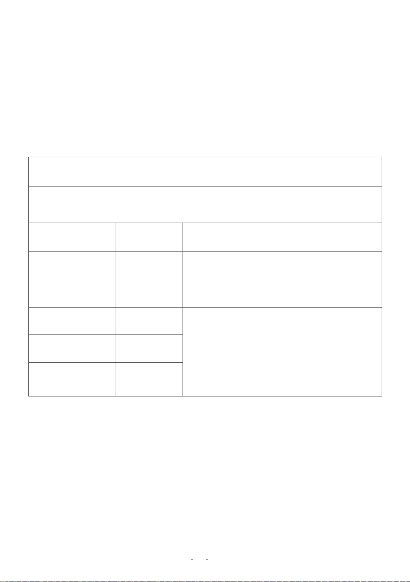
IMMUNITY test
Electrostatic
discharge (ESD)
IEC 61000-4-2
Electrical fast
transient/burst
IEC 61000-4-4
Surge
IEC 61000-4-5
Power frequency
(50/60 Hz)
magnetic field
IEC 61000-4-8
3 A/m
NOTE UT is the a.c. mains voltage prior to application of the test level.
3 A/m
Voltage dips,
short
interruptions
and voltage
variations on
power supply
input lines
IEC 61000-4-11
<5 % UT
(>95 % dip in UT)
for 0,5 cycle
40 % UT
(60 % dip in UT)
for 5 cycles
70 % UT
(30 % dip in UT)
for 25 cycles
<5 % UT
(>95 % dip in UT)
for 5 s
<5 % UT
(>95 % dip in UT)
for 0,5 cycle
40 % UT
(60 % dip in UT)
for 5 cycles
70 % UT
(30 % dip in UT)
for 25 cycles
<5 % UT
(>95 % dip in UT)
for 5 s
Floors should be wood, concrete or
ceramic tile. If floors are covered with
synthetic material, the relative humidity
should be at least 30 %.
Mains power quality should be that of a
typical commercial or hospital
environment.
Mains power quality should be that of a
typical commercial or hospital
environment.
Mains power quality should be that of
a typical commercial or hospital environ-
-ment. If the user of the Endo A Class(LED)
Model device requires continued
operation during power mains interrup-
-tions, it is recommended that the
Endo A Class(LED) Model device be
powered from an uninterruptible power
supply or a battery
If laser output distortion occurs, it may be
necessary to position the Endo A Class(LED)
Model device further from sources of
power frequency magnetic fields or to
install magnetic shielding. The power
frequency magnetic field should be
measured in the intended installation
location to assure that it is sufficiently low.
± 6 kV contact
± 8 kV air
± 2 kV for power
supply lines
± 1 kV for
input/output lines
± 1 kV line(s) to
line(s)
± 2 kV line(s) to
earth
± 1 kV differential
mode
± 2 kV common
mode
± 2 kV for power
supply lines
± 1 kV for
input/output lines
± 6 kV contact
± 8 kV air
IEC 60601 test level Compliance level Electromagnetic environment
17
The Endo A Class(LED) Model device is intended for use in the electromagnetic environment specified below.
The customer or the user of the Endo A Class(LED) Model device should assure that it is used in such an
environment.
Electromagnetic immunity
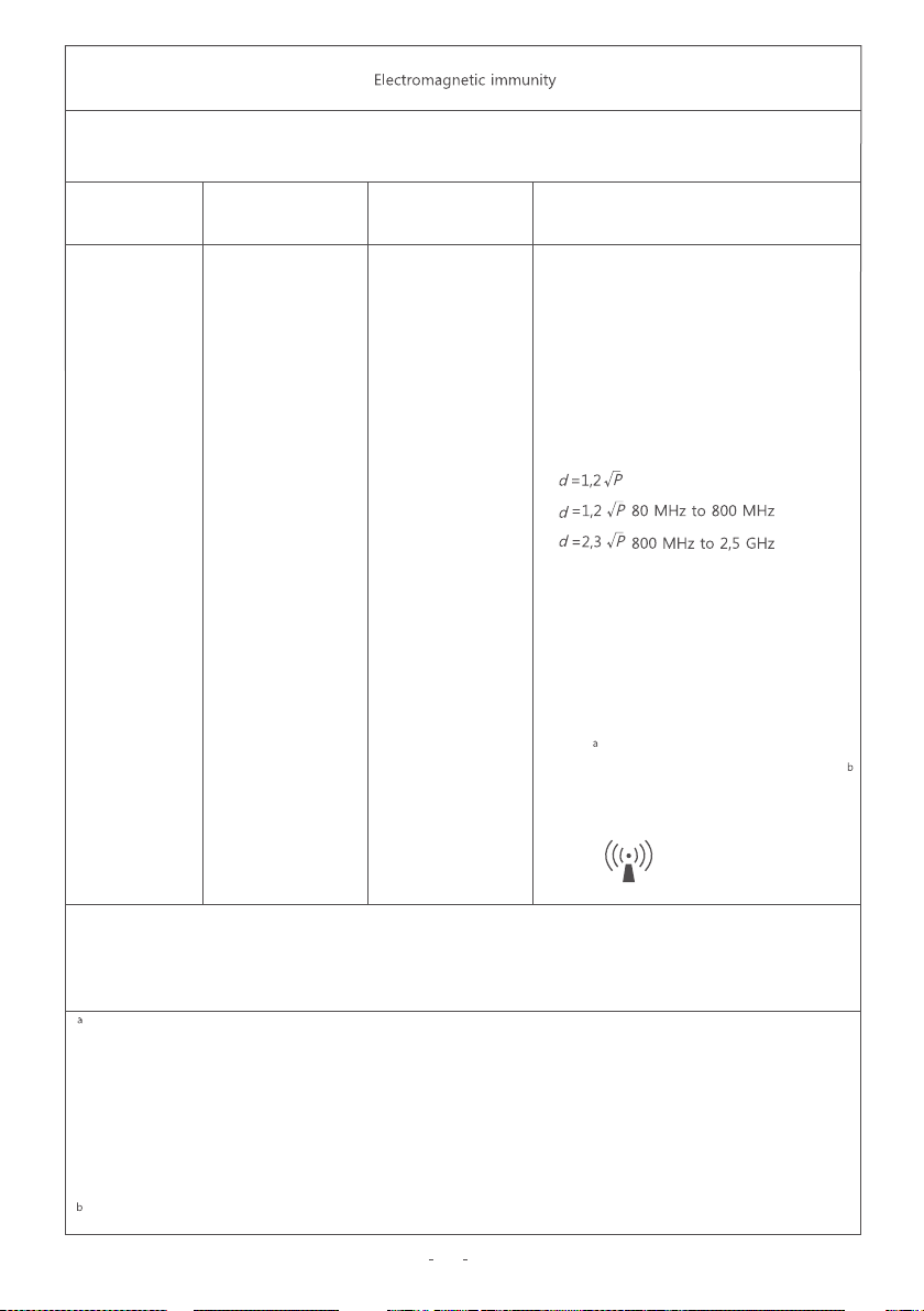
IMMUNITY test
Conducted RF
IEC 61000-4-6
Radiated RF
IEC 61000-4-3
3 Vrms
150 kHz to 80 MHz
3 V/m
80 MHz to 2,5 GHz
IEC 60601 test level Compliance level Electromagnetic environment
3 Vrms
NOTE 1 At 80 MHz and 800 MHz, the higher frequency range applies.
NOTE 2 These guidelines may not apply in all situations. Electromagnetic propagation is affected by
absorption and reflection from structures, objects and people.
Field strengths from fixed transmitters, such as base stations for radio (cellular/cordless) telephones and
land mobile radios, amateur radio, AM and FM radio broadcast and TV broadcast cannot be predicted
theoretically with accuracy. To assess the electromagnetic environment due to fixed RF transmitters, an
electromagnetic site survey should be considered. If the measured field strength in the location in which
the Endo A Class(LED) Model device is used exceeds the applicable RF compliance level above, the
Endo A Class(LED) Model device should be observed to verify normal operation. If abnormal performance
is observed, additional measures may be necessary, such as re-orienting or relocating the Endo A Class(LED)
Model device.
Over the frequency range 150 KHz to 80 MHz, field strengths should be less than 3 V/m.
18
The Endo A Class(LED) Model device is intended for use in the electromagnetic environment specified below.
The customer or the user of the Endo A Class(LED) Model device should assure that it is used in such an
environment.
3 V/m
Portable and mobile RF communications
equipment should be used no closer to
any part of the Endo A Class(LED) Model
device, including cables, than the recom-
-mended separation distance calculated
from the equation applicable to the
frequency of the transmitter.
Recommended separation distance
Where Pis the maximum output power
rating of the transmitter in watts (W)
according to the transmitter manufacturer
and dis the recommended separation
distance in metres (m).
Field strengths from fixed RF transmitters,
as determined by an electromagnetic site
survey, should be less than the
compliance level in each frequency range.
Interference may occur in the vicinity of
equipment marked with the following
symbol:

Recommended separation distances between portable and mobile RF communications equipment and
the Endo A Class(LED) Model device
Rated maximum output
power of transmitter W
Separation distance according to frequency of transmitter m
150 kHz to 80 MHz 80 MHz to 800 MHz 800 MHz to 2,5 GHz
The Endo A Class(LED) Model device is intended for use in an electromagnetic environment in which
radiated RF disturbances are controlled. The customer or the user of the Endo A Class(LED) Model device
can help prevent electromagnetic interference by maintaining a minimum distance between portable and
mobile RF communications equipment (transmitters) and the Endo A Class(LED) Model device as
recommended below, according to the maximum output power of the communications equipment.
For transmitters rated at a maximum output power not listed above, the recommended separation
distance din meters (m) can be estimated using the equation applicable to the frequency of the
transmitter, where Pis the maximum output power rating of the transmitter in watts (W) according to
the transmitter manufacturer.
NOTE 1 At 80 MHz and 800 MHz, the separation distance for the higher frequency range applies.
NOTE 2 These guidelines may not apply in all situations. Electromagnetic propagation is affected by
absorption and reflection from structures, objects and people.
19
Table of contents
Other iM3 Dental Equipment manuals


Popular Dental Equipment manuals by other brands


Ivoclar digital
Ivoclar digital PrograMill Dry operating instructions

Shining 3D
Shining 3D Intraoral Scanner manual

Amanngirrbach
Amanngirrbach Artex BN user manual

Amanngirrbach
Amanngirrbach ceramill therm operating instructions

Flight Dental Systems
Flight Dental Systems FMS-2530 manual

REITEL
REITEL POLYCURE operating instructions

Satelec
Satelec Implant Center 2 user manual

VERDER
VERDER Carbolite Gero CDF 15/1b Installation, operation & maintenance instructions

Miele
Miele G 7881 operating instructions

Great Lakes
Great Lakes Biostar Scan Operation manual

Propel Trampolines
Propel Trampolines VPro+ quick start guide

vita
vita Easyshade Advance 4.0 quick start