ERROR INDICATION
16
When an error is displayed, remedy as follows.
Error indication Cause Remedy
due to a short-circuit.
Switch off the power supply and
check the load.
The teaching is abnor-
mal.
Check the installation condition of the
fiber, or whether the fiber has come
out, and then do teaching again.
Press MODE key to cancel “ .”
After the cancellation, the sensor oper-
ates at the set value conditions before
the error. However, in case the sensitiv-
ity selection function has been set to the
automatic sensitivity setting “ ,” the
sensor operates at optimum sensitivity.
The communication is
abnormal.
Check if the amplifiers mounted in
cascade are disconnected. After the
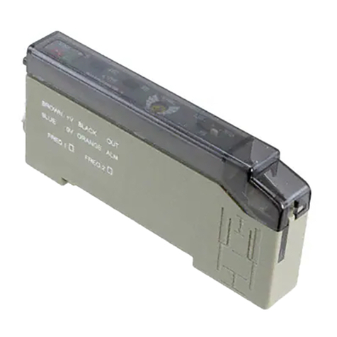
SPECIFICATIONS
18
Type NPN output type PNP output type
Item
Model No.
FX-301-F FX-301P-F
FD-F7 series, FD-F9 series
Supply voltage 12 to 24V DC±10% Ripple P-P 10% or less
Power consumption
Normal operation: 960mW or less
(Current consumption 40mA or less at 24V supply voltage)
Eco-operation: 600mW or less
Output
NPN open-collector transistor
Maximum sink current:
100mA (Note 1)
Applied voltage: 30V DC or less
(between output and 0V)
[at 100mA (Note 1) sink current]
PNP open-collector transistor
Maximum source current:
100mA (Note 1)
Applied voltage: 30V DC or less
(between output and +V)
[at 100mA (Note 1) source current]
Output operation
When Leak is set (F7 mode): OFF when leak is detected.
When Liquid is set (F9 mode): Selectable, either OFF when
no liquid is detected (NC) or
ON when liquid is detected
(NO), with jog switch.
Short-circuit protection
Incorporated
Response time
Sensitivity setting
method Individual teaching / Collective teaching
Fine sensitivity ad-
justment function Incorporated
Ambient temperature
Ambient humidity
Emitting element Red LED (modulated)
Material
Enclosure: Heat-resistant ABS, Transparent cover: Polycarbonate
Weight Approx. 20g
connected together.
2)
If a leak is detected (output: OFF) in
Leak (F7 mode), since the emission
is put in blinking operation, only the
response to return to ON gets de-
layed. (approx. 1 sec.)
Leak removed
Approx.
1
ON
OFF
use the optional quick-connection cables given below.
Main cable (3-core):
CN-73-C1 (cable length 1m), CN-73-C2 (cable length 2m), CN-73-C5
Sub cable (1-core):
CN-71-C1 (cable length 1m), CN-71-C2 (cable length 2m), CN-71-C5
This product has been developed / produced for industrial use only.
Make sure that the power supply is off while wiring and cascading.
Take care that if a voltage exceeding the rated range is applied, or if an AC
power supply is directly connected, the sensor may get burnt or damaged.
Take care that short-circuit of the load or wrong wiring may burn or dam-
age the sensor.
Do not run the wires together with high-voltage lines or power lines or put
them in the same raceway. This can cause malfunction due to induction.
Verify that the supply voltage variation is within the rating.
If power is supplied from a commercial switching regulator, ensure that the frame
ground (F.G.) terminal of the power supply is connected to an actual ground.
In case noise generating equipment (switching regulator, inverter motor,
etc.) is used in the vicinity of this product, connect the frame ground (F.G.)
terminal of the equipment to an actual ground.
-
ply is switched on.
Make sure to use the optional quick-connection cable for the connection of the
2
, or more, cable.
However, in order to reduce noise, make the wiring as short as possible.
Make sure that stress by forcible bend or pulling is not applied to the
sensor cable joint.
Take care that the sensor is not directly exposed to fluorescent lamp
from a rapid-starter lamp, a high frequency lighting device or sunlight
etc., as it may affect the sensing performance.
This product is suitable for indoor use only.
Avoid dust, dirt, and steam.
Take care that the product does not come in contact with oil, grease, or-
ganic solvents, such as thinner, etc., strong acid or alkaline.
and carry out sensitivity teaching periodically.
or explosive gases.
Never disassemble or modify the product.
EEPROM is adopted to this product. It is not possible to conduct teach-
ing 100 thousand times or more, because of the EEPROM's lifetime.
CAUTIONS
17
15
Note: The initial setting at the time of factory shipment is the normal close setting “ .”
Step Digital display Description
1
Confirm if the sensor is in Liquid (F9) mode “ ” in
“INDIVIDUAL TEACHING MODE” or “ COLLEC-
TIVE TEACHING MODE.”
2
Press MODE key to light up MODE indicator / OUT (yellow).
3
Press Jog switch for 3 sec., or more.
(The sensor goes into the NO / NC setting condition.)
MODE indicator / RUN (green) blinks.
4
When Jog switch is turned to “+” side or “–” side, the
digital display (red) and MODE indicator / RUN (green)
blinks, and NO / NC can be chosen.
: Normal close (OFF in liquid absent condition.)
: Normal open (OFF in liquid present condition.)
When Jog switch is pressed, setting display blinks 3
6The sensor returns to Step 2.
7
When MODE key is pressed, the sensor returns to RUN
mode and the incident light intensity is displayed in the
digital display (red).
MODE indicator / RUN (green) lights up.
The setting is complete.
The NO / NC selection can be done by pressing the jog switch for 3
sec., or more, when Liquid (F9) mode “ ” has been set and MODE
indicator / DISP (yellow) lights up. In case of Leak (F7) mode “ ,” the
display does not change to NO / NC selection function.
For the selection method of Leak (F7) mode / Liquid (F9) mode, refer to
“INDIVIDUAL TEACHING MODE” or “ COLLECTIVE TEACHING MODE.”
INTENDED PRODUCTS FOR CE MARKING
19
٨
٨
The models listed under “ SPECIFICATIONS” come with CE
Marking.
As for all other models, please contact our office.
E
<Until June 30 ,2013>
Panasonic Electric Works Europe AG
Rudolf-Diesel-Ring 2, D-83607 Holzkirchen, Germany
<From July 1 ,2013>
Panasonic Marketing Europe GmbH Panasonic Testing Center
18
http://panasonic.net/id/pidsx/global
PRINTED IN JAPAN © Panasonic Industrial Devices SUNX Co., Ltd. 2012
2431-1 Ushiyama-cho, Kasugai-shi, Aichi, 486-0901, Japan
About our sale network, please visit our website.
