Imaging Sciences i-Cat 17-19 User manual

17‐19Operators’Manual
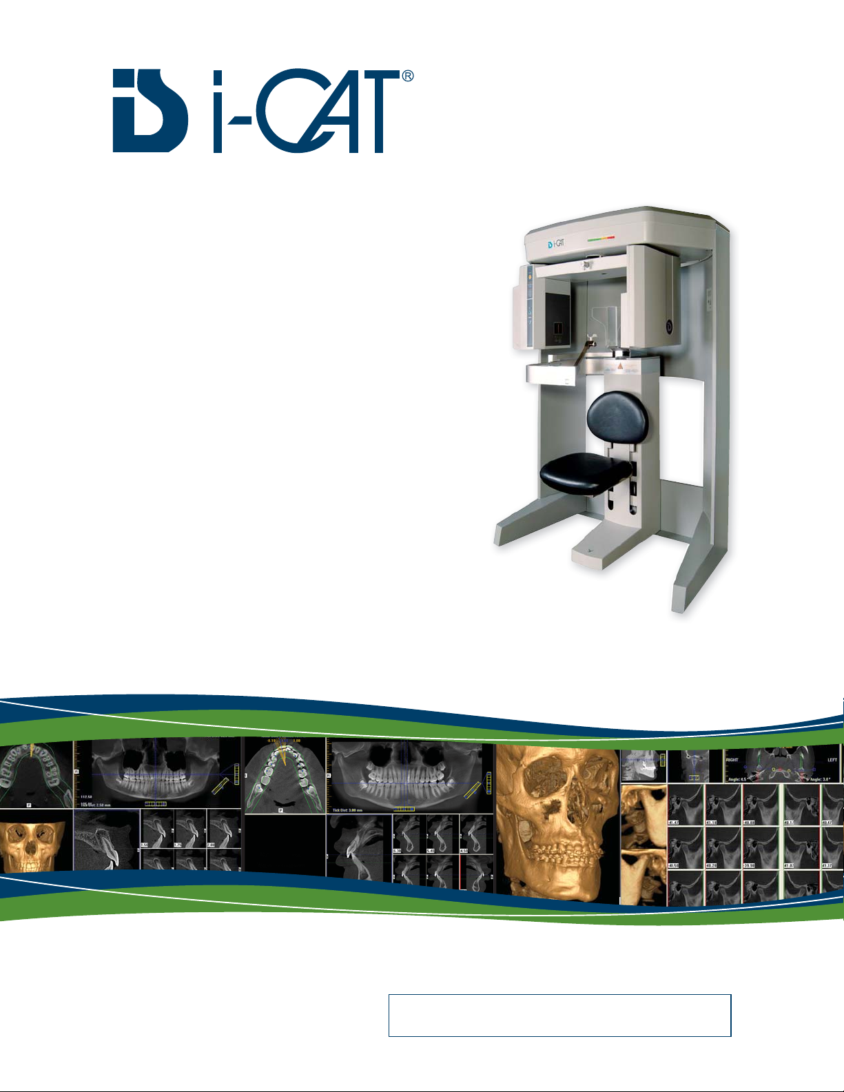
ConeBeamVolumetricTomography
andPanoramicDentalImagingSystem
SerialNumber:ICU08________________
TechnicalSupport:
1‐800‐205‐3570Option5

17-19 Operators’ Manual
990400 Rev C 2010 May 1
Published by Imaging Sciences International
This Operators’ Manual contains original instructions by Imaging Sciences
International for the safe use of the i-CAT 17-19. Imaging Sciences
International reserves the right to make changes to both this Operators’
Manual and to the products it describes. Equipment specifications are
subject to change without notice. Nothing contained within this manual is
intended as any offer, warranty, promise or contractual condition, and must
not be taken as such.
This document may not, in whole or in Part, be copied, photocopied,
reproduced, translated, or reduced to any electronic medium or machine-
readable form without prior consent in writing from Imaging Sciences
International.
i-CAT® is a registered trademark of Imaging Sciences International. Other
names may be trademarks of their respective owners.
No part of this document may be reproduced or transmitted in any form or
by any means, electronic or mechanical, for any purpose, without prior
written permission of Imaging Sciences International. Names and data used
in examples herein are fictitious unless otherwise noted. The software
program described in this document is provided to its users pursuant to a
license or nondisclosure agreement. Such software program may only be
used, copied, or reproduced pursuant to the terms of such agreement. This
manual does not contain or represent any commitment of any kind on the
part of Imaging Sciences International.

990400 Rev C 2010 May 1
Table of Contents
-iii
TABLE OF CONTENTS
What’s New in this Release ..............................................................................-xi
Chapter 1 - Introduction
System Description ...........................................................................................1-1
Intended Use of the Device ..............................................................................1-2
Major System Items ..........................................................................................1-3
About the Operators’ Manual .........................................................................1-3
Conventions Used in the User Manual .................................................................................. 1-3
Standard Limited Warranty .............................................................................1-4
Backup Recommendations ..............................................................................1-5
Chapter 2 - Safety Items
Important Safety Information .........................................................................2-1
Warnings, Cautions, and Notes .............................................................................................. 2-1
Safety Precautions .................................................................................................................. 2-2
Electrical Hazards ................................................................................................................... 2-2
Explosion Hazard .................................................................................................................... 2-3
Mechanical Hazards ............................................................................................................... 2-3
Laser Beam Hazards ............................................................................................................... 2-4
Radiation Safety ...................................................................................................................... 2-5
Radiation Protection Measures .............................................................................................. 2-5
System Safety Devices ......................................................................................2-6
Emergency Stops ..................................................................................................................... 2-6
Warning System ...................................................................................................................... 2-6
Interlock System ...................................................................................................................... 2-6
Sample Site Plan ..............................................................................................2-7
Interlock and Warning System Schematic ............................................................................. 2-8
Cabling Requirements .....................................................................................2-9
Emergency Removal of a Patient ....................................................................2-9
Error Messages ................................................................................................2-9
System Labels .................................................................................................2-10

17-19 Operators’ Manual
990400 Rev C 2010 May 1
-iv
Chapter 3 - System Controls and Indicators
Operator Control Box ......................................................................................3-1
Patient Emergency Stop Control .....................................................................3-2
Patient Alignment Panel ..................................................................................3-2
System Status Indicators ..................................................................................3-2
Chapter 4 - System Startup and Shutdown
System Startup ..................................................................................................4-1
System Shutdown .............................................................................................4-1
Chapter 5 - Managing Patient Data
Patient Information .........................................................................................5-1
Study Information ............................................................................................5-2
Hide/Display Study List ...................................................................................5-4
Delete Patient Scans ........................................................................................5-4
Add New Patient ...............................................................................................5-5
Edit Patient Details ..........................................................................................5-6
Access Patient Data ..........................................................................................5-7
Delete a Patient ................................................................................................5-8
Chapter 6 - Patient Positioning and Protocols
Patient Positioning ...........................................................................................6-1
Patient Chair ........................................................................................................................... 6-2
Gate .......................................................................................................................................... 6-3
Chin Support ........................................................................................................................... 6-3
Head Support and Head Strap. .............................................................................................. 6-4
Alignment Light. ..................................................................................................................... 6-5
Instruct Patients Prior to Exam ......................................................................6-7
Previews and Dry Runs ....................................................................................6-7
Protocol Guidelines ..........................................................................................6-8
Chapter 7 - Acquisitioning (Scanning)
Volume Scans ...................................................................................................7-1
Preview, Dry Run, and Capture Scans ................................................................................... 7-3
Dose Area Product Feature .................................................................................................... 7-6
Quick Picks .............................................................................................................................. 7-8
PAN Scans (Optional) ......................................................................................7-9

990400 Rev C 2010 May 1
Table of Contents
-v
Chapter 8 - Reconstruction of Anatomy
Preview Screen .................................................................................................8-1
Using Quality Control Frames ............................................................................................... 8-3
Panoramic View (Tru-Pan Feature Set as Default) .............................................................. 8-5
Manually Adjusting the Panoramic View .............................................................................. 8-8
Removing Circumference Artifacts ...................................................................................... 8-10
Adjusting MIP, Centerline and Image Type ........................................................................ 8-11
Selecting MIP or Radiograph Display ................................................................................. 8-11
Adjusting Brightness and Contrast ...................................................................................... 8-12
Pan Feature ........................................................................................................................... 8-12
Rotation Feature ................................................................................................................... 8-12
Zoom Feature ........................................................................................................................ 8-13
Back Tool .............................................................................................................................. 8-13
Filter Settings ........................................................................................................................ 8-13
Taking Measurements ...................................................................................8-15
Hounsfield Units ................................................................................................................... 8-15
Distance ................................................................................................................................. 8-18
Rotating Views ...............................................................................................8-20
Saving Views as JPEG Image Files ..............................................................8-21
Saving and Loading Workups .......................................................................8-21
Save a Workup ...................................................................................................................... 8-21
Load an Existing Workup ..................................................................................................... 8-23
Delete an Existing Workup ................................................................................................... 8-24
Viewing and Reconstructing Raw Patient Scans ..........................................8-25
Quantum IQ .......................................................................................................................... 8-27
Chapter 9 - Detail Screens
Preview Screen .................................................................................................9-1
Implant Planning Screen .................................................................................9-2
Estimate the Nerve Canal .......................................................................................................9-7
Ceph Screen ...................................................................................................9-16
MPR Screen ...................................................................................................9-18
TMJ Screen ....................................................................................................9-22

17-19 Operators’ Manual
990400 Rev C 2010 May 1
-vi
Chapter 10 - Tools
DICOM Setup .................................................................................................10-1
DICOM Database and DICOM Export Setup ..................................................................... 10-1
PACS ..................................................................................................................................... 10-3
DICOM Character Set for New Files ................................................................................... 10-3
Check Read/Write Access to Image Database ..............................................10-5
Export DICOM ...............................................................................................10-6
Export an Original CT or PAN study ................................................................................... 10-6
Export a Rotated CT study .................................................................................................... 10-7
Export Sure Smile Studies .................................................................................................... 10-7
Create Export CD ...........................................................................................10-8
Erase CD-RW ...................................................................................................................... 10-10
Output to Folder .................................................................................................................. 10-10
Import Study .................................................................................................10-11
Reporting ......................................................................................................10-12
Run Report .......................................................................................................................... 10-12
Create New Report .............................................................................................................. 10-13
Modify Existing Report ....................................................................................................... 10-17
Start External Applications .........................................................................10-17
Chapter 11 - Calibration
Panel Calibration ...........................................................................................11-1
Collimators Calibration .................................................................................11-3
Geometry Calibration .....................................................................................11-4
Chapter 12 - Quality Assurance
QA Phantom Test ...........................................................................................12-1
Line Pair Evaluation ............................................................................................................. 12-4
Distance Measurement Test ................................................................................................. 12-5
Hounsfield Unit (HU) Measurements .................................................................................. 12-6
QA Water Phantom Test ................................................................................12-9
Noise Level Test .................................................................................................................. 12-12
Uniformity Test ................................................................................................................... 12-13
PAN Phantom Test ......................................................................................12-14
Radiation Output Test ..................................................................................12-17
Measured Dose .................................................................................................................... 12-18
Interpretation ...................................................................................................................... 12-18

990400 Rev C 2010 May 1
Table of Contents
-vii
Chapter 13 - Radiation Environment Survey
Conditions of Operation – 8.9 and 26.9 Second Scans ................................13-2
Scatter Measurements for 8.9 Second Scans ................................................13-2
Diameter 16cm 8.9 Second Scan ......................................................................................... 13-3
Scatter Measurements for 26.9 Second Scan ................................................13-4
Diameter 16cm 26.9 Second Scan ........................................................................................ 13-4
Conditions of Operation – PAN Scans ..........................................................13-5
Scatter Measurements for 20 Second PAN Scan, Large 2x2 .......................13-6
Scan Times and Settings ................................................................................13-7
Dose and Imaging Performance Information ..............................................13-8
Dose Profile ....................................................................................................13-9
Sensitivity Profile .........................................................................................13-11
Drywall Attenuation .....................................................................................13-12
Recommended Operating Requirements .....................................................13-13
X-ray Tube Assembly ...................................................................................13-14
Chapter 14 - Product Information
Technical Specifications ................................................................................14-1
Power Requirements ......................................................................................14-2
Apparent Resistance of Supply Mains ................................................................................. 14-3
Weight .............................................................................................................14-3
Environmental Specifications .......................................................................14-4
Operating ............................................................................................................................... 14-4
Transportation and Storage .................................................................................................. 14-4
Acquisition Computer ....................................................................................14-4
Patient Support Chair ....................................................................................14-4
Disposal ..........................................................................................................14-4
Extension Cords .............................................................................................14-5
External Item .................................................................................................14-5
Cleaning .........................................................................................................14-5
Electromagnetic or other Interference
(Emissions and Immunity) ............................................................................14-5
Equipment Standards .....................................................................................14-7
Equipment Class ............................................................................................14-7
Preventive Maintenance Schedule - for Owner / User .................................14-8

17-19 Operators’ Manual
990400 Rev C 2010 May 1
-viii
Planned Maintenance - 12 Month Schedule ................................................14-8
Cleaning ................................................................................................................................ 14-9
Planned Maintenance Checklist ........................................................................................... 14-9
Replaceable Parts ........................................................................................14-10
Supplemental Components ..........................................................................14-11
Optional PAN Scan Accessories ..................................................................14-12
System Gantry Dimensions ..........................................................................14-13
Chapter 15 - Networking Support Setup
Networking Support Overview .......................................................................15-1
Networking Data Flow ...................................................................................15-1
Network Support Installation/Setup ..............................................................15-2
Provide Network Storage ...................................................................................................... 15-2
Install Sweeper Service ......................................................................................................... 15-3
Configure Sweeper Service ................................................................................................... 15-3
Migrate from Standalone to Server ...................................................................................... 15-4
Change Image Root Folder .................................................................................................. 15-5
Start the Sweeper ................................................................................................................... 15-5
Sweeper Service ..............................................................................................15-5
Sweeper Controller ................................................................................................................ 15-6
Network Failures ...........................................................................................15-6
No Network Access at Startup .............................................................................................. 15-7
Network Fails During Operations ........................................................................................ 15-8
Limitations of Networking Support ...............................................................15-8
Chapter 16 - Remote System Import and Export
Remote System Import and Export Overview ...............................................16-1
Remote System Import ...................................................................................16-1
Import Installation and Setup .......................................................................16-2
Set Up DICOM Worklist Interface ....................................................................................... 16-2
Set Up Practice Management Interface ............................................................................... 16-4
Import Patient Data .......................................................................................16-5
Remote System Export (RSSM) .....................................................................16-6
RSSM Installation and Setup ............................................................................................... 16-6
RSSM Logs .......................................................................................................................... 16-10
Send Patient Data to a Remote System .............................................................................. 16-10

990400 Rev C 2010 May 1
Table of Contents
-ix
RSQM ...........................................................................................................16-12
RSQM Installation and Setup ............................................................................................ 16-12
Query and Retrieve Images ................................................................................................ 16-15
Status Messages .................................................................................................................. 16-16
Appendix A - iCATVision & iCATTransfer
Workstation Minimum Requirements ....................................................................................A-2
Laptop Minimum Requirements .............................................................................................A-2
File Structure Setup ................................................................................................................A-2
Install iCATVision ..................................................................................................................A-3
iCATVision Setup ....................................................................................................................A-4
iCATTransfer .................................................................................................. A-4
Install iCATTransfer .............................................................................................................A-5
iCATTransfer Passcode ..........................................................................................................A-5
iCATTransfer Setup ................................................................................................................A-6
Configure iCATTransfer ........................................................................................................A-6
Accessing i-CAT® DICOM Data ...........................................................................................A-7
Appendix B - Three Dimensional Volume Rendering (3DVR)
Open Database ................................................................................................ B-1
Axial Functions ............................................................................................... B-2
Paging ......................................................................................................................................B-2
W/L (Window/Level) ...............................................................................................................B-3
ROI (Region of Interest) .........................................................................................................B-3
Distance ...................................................................................................................................B-4
Identify .....................................................................................................................................B-4
Remove Object .........................................................................................................................B-6
Hounsfield Unit Calibration Offset ........................................................................................B-6
View Volume ................................................................................................... B-8
Projection Type .......................................................................................................................B-9
Volume Edit ...........................................................................................................................B-10
VR Functions ........................................................................................................................B-11
Pop Up Menu ........................................................................................................................B-14
View Full Screen ...................................................................................................................B-15

17-19 Operators’ Manual
990400 Rev C 2010 May 1
-x
Appendix C - Quick Reference
Navigating the Interface ................................................................................. C-1
Tools for Viewing this Image .................................................................................................C-1
Suggestions for Adjusting Panoramic Map ...........................................................................C-2
Filtering Defaults ....................................................................................................................C-2
Removing Circumference Artifact .........................................................................................C-2
Saving and Loading Workups ................................................................................................C-2
Keyboard Shortcuts .................................................................................................................C-2
Implant Planning Screen ................................................................................ C-3
Panoramic Map .......................................................................................................................C-4
Axial Slice Position .................................................................................................................C-4
Ceph Screen .................................................................................................... C-5
MPR Screen .................................................................................................... C-5
Install Case Studies from CDs ........................................................................ C-6
TMJ Planning Screen ..................................................................................... C-6
Create Export CDs .......................................................................................... C-6
Appendix D - System Labels
English ............................................................................................................. D-1
Français ........................................................................................................... D-3
Deutsch ............................................................................................................ D-5
Italiano ............................................................................................................ D-7
Polski ............................................................................................................... D-9
Portuguê ........................................................................................................ D-11
Español .......................................................................................................... D-13
Svenska .......................................................................................................... D-15
简体中文
(Chinese) ...................................................................................... D-17
繁體中文 (Taiwan) ....................................................................................... D-19
한국어 (Korean) ............................................................................................ D-21
日本語 (Japanese) ........................................................................................ D-23
Česky .............................................................................................................. D-25
Nederlands ..................................................................................................... D-27
Русский язык ................................................................................................ D-29
Român ........................................................................................................... D-32
Türkçe ............................................................................................................ D-34

990400 Rev C 2010 May 1
What’s New in this Release
-xi
What’s New in this Release
Change Description Link to Topic
User-selectable image processing
feature, Quantum IQ, added to
smooth noise in soft tissue areas of
reconstructed scans.
Quantum IQ
Sure Smile compatibility enabled
between VisionQ studies and Sure
Smile software.
Export Sure Smile Studies
Dose Area Product feature
(available by license) added to
display the patient radiation dose
measurement for each exposure.
Dose Area Product Feature
DICOM modules RSSM and RSQM
are now able to send and receive
datasets using LEI VR transfer
syntax.
RSSM Installation and Setup
RSQM Installation and Setup
Storage Commitment feature
enhanced to enable selection of a
separate connection for DICOM
storage.
RSSM Installation and Setup
Additional patient study information
and status has been added to the
Study List.
Study Information
DICOM Export feature enhanced to
enable export of a volume scan with
rotation applied.
Export DICOM
Add Rotated Volume

17-19 Operators’ Manual
990400 Rev C 2010 May 1
-xii
Import Study feature added to
enable Vision patient studies to be
imported into the system from a CD
or network.
Import Study
Rescan feature added to enable a
rescan of the entire study list
database if corruption of the list is
suspected.
Rescan
Auto Send feature added to enable
reconstructed datasets to be sent
automatically to a selected server.
PACS
New option added to the Tools
Setup dialog for designating a Fast
System.
Fast System
Dolphin 3D, TxStudio and
InVivoDental applications can now
be launched from the Tools menu.
InVivoDental and TxStudio can also
be launched for a selected study
from the Study List.
Start External Applications
Preview scans are saved
automatically as .jpg files.
Preview, Dry Run, and Capture
Scans
iCATVision Standalone is supported
on Windows 7 Professional or
Ultimate (32-bit or 64-bit modes).
Workstation Minimum
Requirements
Change Description Link to Topic

990400 Rev C 2010 May 1 1-1
Chapter
1 Introduction
System Description
The system is a Cone Beam Volumetric Tomography and
Panoramic X-ray device used for dental head and neck applications.
The system consists of a Scanner and Computer Workstation which
is suitable for an in-office environment.
This scanning device is an open design that allows Patients to sit
upright during a procedure. An electric powered seat is built into the
device for proper Patient positioning.
17-19 i-CAT®Imaging System
HEAD
SUPPORT
BACKPLATE
CHIN
SUPPORT
GATE
(SWINGS OPEN,
MAGNETS LOCK
IN PLACE)
PATIENT
ALIGNMENT
PANEL (ADJUSTS
CHAIR UP/DOWN)
HEAD SUPPORT
BACK PLATE
KNOB
(SLIDES TO
ADJUST THE
POSITION OF THE
HEAD SUPPORT)
MOTORIZED
CHAIR
(MOVES
UP/DOWN VIA
BUTTONS ON
PATIENT
ALIGNMENT
PANEL)

17-19 Operators’ Manual
990400 Rev C 2010 May 1
1-2
The system consists of a Scanner and Computer Workstation. In
order for the system to operate, both the Scanner and Computer
Workstation must be turned ON.
The system captures data for 3D Skull Reconstruction for the
following procedures:
•Implants
•TM Joints
•Reconstructed Panoramic
•Reconstructed Cephalometrics
•Airway / Sinus, etc.
•Nerve Canal
•PAN - Optional Conventional Digital Panoramic Feature
Cone Beam Volumetric Tomography is a medical imaging
technique that uses X-rays to obtain cross-sectional images of the
head or neck. Quality of the images depends on the level and amount
of X-ray energy delivered to the tissue. Imaging displays both high-
density tissue, such as bone, and soft tissue. When interpreted by a
trained Physician, these images provide useful diagnostic
information.
Intended Use of the Device
The Imaging Sciences International (ISI) Scanner constructs a three
dimensional model from images taken during a rotational X-ray
sequence. The scanner is intended to be used whenever a dentist,
oral surgeon, or other physician needs 3D information of high
contrast objects. The system is designed for imaging of TM joint
studies, mandible and maxilla for implant planning, sinuses, and
other areas of the maxillofacial complex.
CAUTIONCAUTION
U.S. Federal law restricts this device to sale by or on the order of a
dentist or other licensed practitioner.

990400 Rev C 2010 May 1
Introduction
1-3
Major System Items
The system is comprised of the following major items:
•Scanner
•Computer Workstation
•Operator Control Box with 50 ft. (15.2m) Cable
•Patient Emergency Stop Box with 10 ft. (3m) Cable
•Interlock Jumper Cable, 8 inch (20cm)
•Interlock Cable 50 ft. (15.2m)
•Warning Light Cable 50 ft. (15.2m)
•Chair Connection Cable, 10 ft. (3m)
•Power Cable, 15 ft.(4.6m)
•CAT 5 Ethernet Cable, 50 ft. (15.2m)
About the Operators’ Manual
This documentation describes the safe and effective operation of the
system. The information is intended to provide trained
Technologists and Physicians the necessary guidance to operate the
system in a safe and effective manner.
Conventions Used in the User Manual
•Keyboard keys are represented in a Bold font.
For example, “Press Start.”
•Menu items and button names on the user interface display
are represented in a Bold font.
For example, “At the Print window, click the Print button.”
•Keyboard entries are represented in bold Courier font.
For example, “Type QA Test in the filename box.”

17-19 Operators’ Manual
990400 Rev C 2010 May 1
1-4
Standard Limited Warranty
Imaging Sciences International (ISI) warrants the original purchaser
that this hardware system will be free from defects for a period of
one (1) year from the date of delivery. During the warranty period,
ISI will correct any defects in material or workmanship, at no charge
for materials. Any replacement parts shall be new or serviceable
used parts and are warranted for the remainder of the original
warranty or thirty (30) days, whichever is longer. The warranty
period is not extended as a result of purchasing any additional parts
from ISI. The original purchaser must promptly notify ISI in writing
if there is a defect in material or workmanship. Written notice in all
events must be received by ISI before expiration of the warranty
period. This warranty is not transferable.
This One-Year Limited Warranty covers normal use. ISI does not
warrant or cover:
•Damage caused by impact with other objects, dropping,
falls, spilled liquids or immersion in liquids
•Damage caused by a disaster such as fire, flood, wind,
earthquake, or lightning
•Damage caused by unauthorized attachments, alterations,
modifications or foreign objects
•Damage caused by peripherals
•Damage caused by failure to provide a suitable environment
•Damage caused by the use of the hardware system for
purposes other than those for which it was designed
•Damage from improper maintenance
•Damage from improper electrical connection or supply
•Damage caused by any other abuse, misuse, mishandling, or
misapplication
•Damage to acquisition computer, software, or operating
system caused by;
o Unauthorized additions or changes
o Viruses, spyware, or gaming software
o Damage caused by Network or Operating Engineers
o Damage from the use of this machine or computer
for any other purpose

990400 Rev C 2010 May 1
Introduction
1-5
o Applications other than its intended use
o Damage caused by third party software
o Damage caused by unauthorized changes to the
system software
o Damage caused by unauthorized upgrades, additions
or deletions
o Damage caused by internet use, or any other
unauthorized application.
Under no circumstances shall ISI be liable for any special,
incidental, or consequential damages based upon breach of
warranty, breach of contract, negligence, strict liability or any other
legal theory. Such damages include, but are not limited to, loss of
data, loss of profits, loss of revenue, loss of use of hardware system
or any associated equipment, cost of capital, cost of substitute or
replacement equipment, facilities or services, down time,
purchaser's time, the claims of third party, including customers, and
injury to property.
Backup Recommendations
The owner/operator is responsible for performing data backup. It is
recommended that the following data be backed up regularly:
•Imaging Sciences International folder (located in
C:\Program Files)
•Patient data (typically LocalRoot or ImageRoot folder)
•For Networked systems, patient data on server (typically
NetworkRoot folder)
Disclaimer of Warranties
The warranty stated above is the only warranty applicable to this product,
all other warranties, expressed or implied including all implied warranties
of merchantability or fitness for a particular purpose, are hereby dis-
claimed. No oral or written information or advice given by ISI, its agents
or employees shall create a warranty or in any way increase the scope of
this warranty

17-19 Operators’ Manual
990400 Rev C 2010 May 1
1-6

990400 Rev C 2010 May 1 2-1
Chapter
2 Safety Items
Important Safety Information
Imaging Sciences designs its products to meet stringent safety
standards. However, to maintain the safety of Operators and
Patients, you must operate the equipment correctly and properly and
ensure the equipment is properly maintained.
It is essential to follow all safety instructions, warnings, and cautions
specified in this manual to ensure the safety of Patients and
Operators. In addition, read and observe all danger and safety
labelling on the system.
Before attempting to use the equipment for any patient examination,
read, understand, and know how to implement the Emergency Stops
on the system.
Warnings, Cautions, and Notes
Before attempting to operate the equipment, it is recommended that
you read this manual thoroughly including all cautions and
warnings. This guide uses the following conventions to describe
situations that are potential hazards to the Patient or Operator,
potential loss of data, or potential damage to the equipment.
WARNING
Warnings are intended to alert the user that failure to follow the
procedure could cause fatal or serious injury to the user, Patient, or
any other person, or result in a misdiagnosis.
CAUTIONCAUTION
Cautions are intended to alert the user that failure to follow the
procedure could cause damage to the equipment or cause loss of
data.

17-19 Operators’ Manual
990400 Rev C 2010 May 1
2-2
ADVISORY: Advisories are used to defined information for the
operator regarding advice towards use of the device or a process.
NOTE: Notes are used to highlight important or unusual points to be
brought to the attention of the operator.
Safety Precautions
WARNING
The X-ray device may be dangerous to the Patient and Operator if
you do not observe and follow operating instructions. Do not operate
this system unless you have received training to perform a
procedure.
WARNING
Do not remove covers or cables on system. High voltage is present
in the system. To avoid personal injury from electrical shock, do not
operate the system with any covers open or cables removed.
WARNING
Closing the Gate creates a pinch point. Keep hands and other body
parts clear when closing Gate.
Electrical Hazards
Installation and system wiring must meet all requirements of local
governing authorities. Please check your local authorities and local
codes to determine best practices for a safe installation.
Do not place any liquid or food on any part of the consoles or other
modules of the system.
Observe all fire regulations. Fire extinguishers should be provided
for both electrical and non-electrical fires. All operators should be
fully trained in the use of fire extinguishers and other fire-fighting
equipment and in local fire procedures.
Table of contents
Popular Medical Equipment manuals by other brands

Karl Storz
Karl Storz ALKATOUT 30623 AR instruction manual

Ultrasound Technologies
Ultrasound Technologies PD1 series Service manual

medi
medi protect.ROM Instructions for use

ProMed
ProMed INH-2.1 Instruction leaflet

Stryker
Stryker Visum 450 Installation and service manual

Thuasne
Thuasne Sleeq Flex Instructions for use