imec NEUROPIXELS 1.0 User manual

NEUROPIXELS 1.0
User Manual
February 13, 2020

NEUROPIXELS 1.0 USER MANUAL V1.0.5
2
Important Information
THE NEUROPIXELS PROBES ARE ONLY INTENDED FOR RESEARCH USE ONLY (“RUO”) IN NON-HUMAN SUBJECTS SUCH AS SMALL
ANIMALS INCLUDING RODENTS AND NON-HUMAN PRIMATES. THESE NEUROPIXELS PROBES SHOULD NOT BE USED IN
HUMANS AND ARE NOT MANUFACTURED OR APPROVED FOR HUMAN USE. THEY HAVE NO PROVEN HUMAN EFFICACY AND
ARE NOT INDICATED FOR HUMAN USE OR ANY FORM OF CLINICAL USE.
About Neuropixels
The Neuropixels 1.0 neural probe is an advanced silicon CMOS digital integrated microsystem and a tool for neuroscience
research. It was developed through a collaboration funded by Howard Hughes Medical Institute (HHMI), Wellcome Trust, Gatsby
Charitable Foundation and Allen Institute for Brain Science. Probes were designed, developed and fabricated at imec, Leuven
Belgium in collaboration with HHMI Janelia Research Campus, Allen Institute for Brain Science and University College London.
Legal Disclaimer
The contents of this document are provided by imec, 'as is'. Imec makes no representations nor warranties with respect to the
accuracy or completeness of the contents of this publication and reserves the right to make changes to the specification at any
time without notice. All trademarks are the property of their respective owners.
The Neuropixels 1.0 probes are ONLY distributed to the Neuroscience Research Community under the “IMEC GENERAL TERMS
AND CONDITIONS OF SALE OF NEUROPIXELS 1.0 PROBES”.
Imec is a registered trademark for the activities of IMEC International (a legal entity set up under Belgian law as a “stichting van
openbaar nut”), imec Belgium (IMEC vzw supported by the Flemish Government), imec the Netherlands (Stichting IMEC
Nederland, part of Holst Centre which is supported by the Dutch Government), imec Taiwan (IMEC Taiwan Co.) and imec China
(IMEC Microelectronics (Shanghai) Co. Ltd.) and imec India (Imec India Private Limited), imec Florida (IMEC USA nanoelectronics
design center).

NEUROPIXELS 1.0 USER MANUAL V1.0.5
3
List of abbreviations
AP
Action Potential.
API
Application Programming Interface.
ASIC
Application Specific Integrated Circuit.
BIST
Built-In Self-Test.
CMOS
Complementary Metal-Oxide-Semiconductor.
DIW
De-Ionized Water.
EEPROM
Electrically Erasable Programmable Read-Only Memory.
ESD
Electro-Static Discharge.
FPC
Flexible Printed Circuit.
FPGA
Field Programmable Gate Array.
GND
Ground.
HS
Headstage.
HST
Headstage Test Dongle.
ID
Identification.
I/O
Input and/or Output.
IPA
Isopropyl Alcohol.
LDO
Low-DropOut.
LED
Light-Emitting Diode.
LFP
Local Field Potential.
MSVC
Microsoft Visual C++.
MXI
Multisystem eXtension Interface.
NI
National Instruments.
PBS
Phosphate-Buffered Saline.
PCB
Printed Circuit Board.
PC
Personal Computer.
PCIe
Peripheral Component Interconnect Express.
PXIe
PCI eXtensions for Instrumentation express.
REF
(External) Reference.
RT
Room Temperature.
SEM
Scanning Electron Microscope.
SMA
Sub-Miniature version A.
SMD
Surface-Mount Devices.
USB-C
Universal Serial Bus Type-C.
ZIF
Zero Insertion Force.

NEUROPIXELS 1.0 USER MANUAL V1.0.5
4
Definitions of technical terms
•ASIC: Integrated circuit that contains recording electrodes, amplifiers, multiplexers and
digitizers.
•Probe Shank: Implanted part of the probe ASIC (Figure 3).
•Probe Base: Non-implanted part of the probe ASIC (Figure 3).
•Flex: Flexible PCB (or FPC) onto which the probe ASIC and additional passive and active
components are mounted (Figure 3). It connects to the HS.
•Control System: System components required to enable control of and data streaming from
Neuropixels probes. These entail the headstage, interface cable and PXIe acquisition module.
•Headstage: Miniature board that enables reliable power supply to the probe and is essential for
bi-directional data communication from/to the probe (Figure 7).
•Headstage Test Dongle: a small test box (Figure 10) that plugs into the ZIF connector of a
headstage. Its purpose is to help verify the functionality of a Headstage.
•Interface Cable: Thin and flexible cable for power and bidirectional data transmission between
HS and PXIe acquisition module (Figure 8).
•PXIe Acquisition Module: Custom-made PCB module with two FPGAs for probe configuration,
data acquisition and transmission to PC via PCIe interface (Figure 9).
•Port: USB-C plug on the front panel of the PXIe acquisition module. Each front panel contains
4 ports (Figure 9) allowing connection of up to 4 interface cables.
•PXIe Chassis: Houses PXIe modules and connects them with a high-performance backplane that
offers timing and synchronization capabilities.
•Driver: The software files that need to be installed on the host PC to enable communication
with the Neuropixels control system and to develop custom application software.

NEUROPIXELS 1.0 USER MANUAL V1.0.5
5
Table of Contents
1ABOUT THIS MANUAL .............................................................................................................................6
1.1 RELATED DOCUMENTATION .................................................................................................................6
2GETTING STARTED...................................................................................................................................7
2.1 UNPACKING AND HANDLING ................................................................................................................7
2.2 HARDWARE & SYSTEM REQUIREMENTS...............................................................................................7
2.3 DRIVERS.................................................................................................................................................9
2.4 APPLICATION SOFTWARE......................................................................................................................9
Existing Software ..............................................................................................................................9
Developing New Software.................................................................................................................9
2.5 PROBE CONFIGURATION FILES............................................................................................................10
3NEUROPIXELS HARDWARE DESCRIPTION ..............................................................................................11
3.1 PROBE..................................................................................................................................................11
3.2 HEADSTAGE.........................................................................................................................................14
3.3 INTERFACE CABLE................................................................................................................................15
3.4 PXIE ACQUISITION MODULE ...............................................................................................................16
3.5 HEADSTAGE TEST DONGLE..................................................................................................................18
4INSTALLATION AND CONFIGURATION ...................................................................................................20
4.1 PXIE CHASSIS AND REMOTE CONTROLLER..........................................................................................20
4.2 NEUROPIXELS HARDWARE..................................................................................................................22
PXIe Acquisition Module .................................................................................................................22
Drivers.............................................................................................................................................23
Remote FPGA update......................................................................................................................33
5USING THE SYSTEM ...............................................................................................................................34
5.1 CONNECTING THE SYSTEM COMPONENTS .........................................................................................34
Probe to HS .....................................................................................................................................34
HS to PXIe Acquisition Module........................................................................................................34
5.2 PROBE AND SYSTEM CONFIGURATION...............................................................................................34
Electrode Selectivity ........................................................................................................................35
Reference Selection.........................................................................................................................35
5.3 SUPPORT AND TROUBLESHOOTING....................................................................................................36
Visual Inspection .............................................................................................................................36
Built-In Self-Tests ............................................................................................................................36
Headstage Test Dongle ...................................................................................................................37
Gain and Noise Measurements.......................................................................................................37
PROBE HANDLING, CLEANING, STORAGE..............................................................................39
SOLDERING ...........................................................................................................................42
ESD SAFETY...........................................................................................................................45

NEUROPIXELS 1.0 USER MANUAL V1.0.5
6
1About This Manual
This document describes the key features of the Neuropixels 1.0 probe and control system and how to
install them prior to use. The Neuropixels hardware consists of:
•The Neuropixels probe.
•The Neuropixels control system which contains:
oA headstage.
oAn interface cable.
oA PXIe acquisition module.
•A headstage test dongle.
Even if you have read articles on the Neuropixels 1.0 probes and feel that you are familiar with using
the Neuropixels probes we request and encourage you to carefully read the latest version of this
User
Manual
to refresh your knowledge and remain up-to-date on possible changes that are relevant to the
use of your probes.
If you are unfamiliar with the Neuropixels probes, then it is absolutely essential and imperative that you
carefully read the complete
User Manual
.
Please check www.neuropixels.org or www.neuropixels.info for the latest version of this manual.
1.1 Related Documentation
The following documents and online resources contain information that you might find helpful as you
read this manual:
•Wiki: https://github.com/cortex-lab/neuropixels/wiki.
•Application Software:
oSpikeGLX: http://billkarsh.github.io/SpikeGLX/.
oOpen Ephys: https://open-
ephys.atlassian.net/wiki/spaces/OEW/pages/77332482/Neuropixels.
•Brochures:
oNeuropixels 1.0 Probe (available on www.neuropixels.org or www.neuropixels.info).
oControl System (available on www.neuropixels.org or www.neuropixels.info).
•API Manual (upon request).
•Technical Datasheets (upon request)
oNeuropixels 1.0 Probe/ASIC Datasheet.
oSystem Datasheet.
•Mechanical drawing of the aluminum metal cap (available on www.neuropixels.org or
www.neuropixels.info).
NEUROPIXELS 1.0 USER MANUAL V1.0.5
7
2Getting Started
2.1 Unpacking and Handling
Upon receiving the Neuropixels probe and control system immediately inspect the shipping boxes and
content for damage. In case of damage, please carefully read the included warranty document and
follow the instructions.
The probes arrive in black shipping boxes containing black foam inlays. Both the box and foam inlays
are manufactured from ESD compliant (antistatic) material. All system components are also delivered in
antistatic bags or boxes. It is advised to wear ESD protective equipment when handling the probes and
system components. Carefully read the guidelines on probe handling (Appendix A), soldering
(Appendix B) and ESD safety (Appendix C).
2.2 Hardware & System Requirements
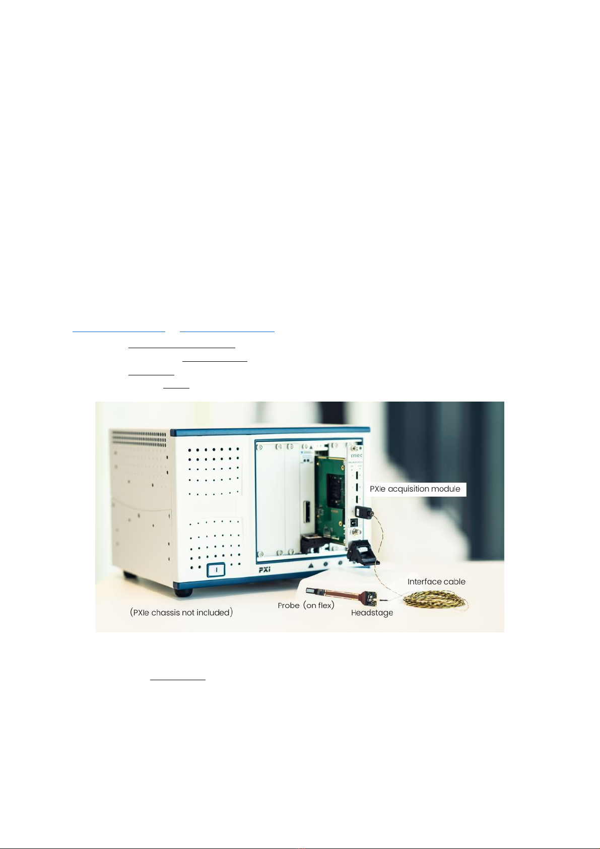
Figure 1 shows the Neuropixels 1.0 probe and control system that can be purchased from imec through
www.neuropixels.org or www.neuropixels.info. To get started you need:
•one PXIe acquisition module,
•one data/power interface cable,
•one headstage and
•at least one probe.
Figure 1: Neuropixels 1.0 probe and control system (chassis not included)
In addition, the PXIe chassis required for using the PXIe acquisition module must be purchased
separately from third-party suppliers such as National Instruments (NI), Keysight or Adlink. Below we
provide recommendations for PXIe chassis using a remote controller (MXI-Express interface).
For first-time probe users intending to use less than 3 PXIe acquisition modules (or 12 probes)
simultaneously, we recommend the following entry-level chassis and remote controller combination:
NEUROPIXELS 1.0 USER MANUAL V1.0.5
8
•PXI-Express chassis: NI PXIe-1071 (4-Slot, Up to 3 GB/s)
1
.
•Power cord for chassis
2
.
•MXI-Express interface: NI PCIe-8381 and PXIe-8381 (Gen 2 x8, 1 Port; incl. one MXI-Express x8
copper cable, 3m)
3
.
For more advanced, multi-probe users planning to use 3 or more PXIe acquisition modules
simultaneously we recommend:
•PXI-Express chassis: NI PXIe-1082
4
.
•Power cord for chassis
5
.
•MXI-Express interface: NI PCIe-8381 and PXIe-8381 (Gen 2 x8, 1 Port; incl. one MXI-Express x8
copper cable, 3m)
6
.
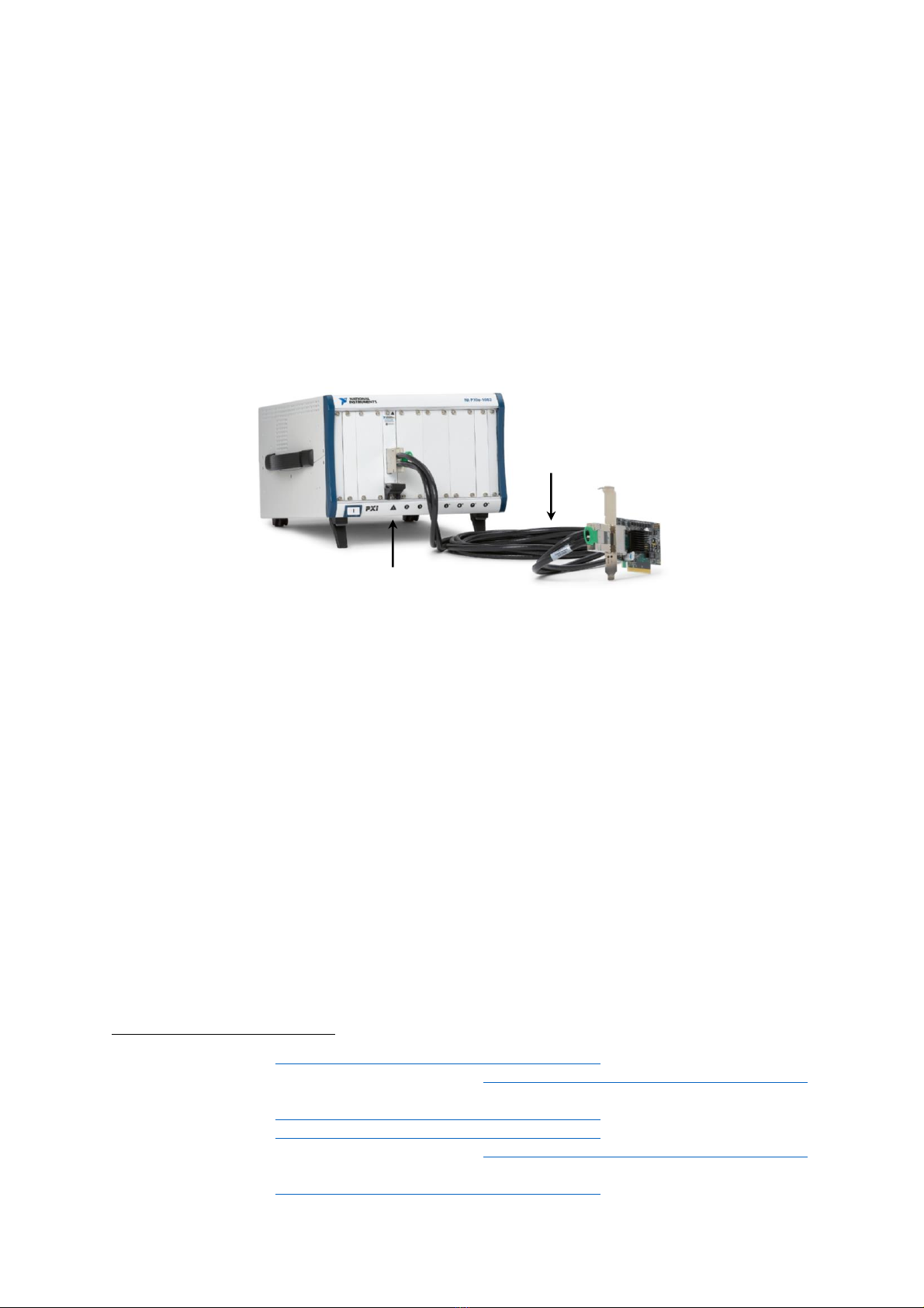
Figure 2: Recommended PXIe chassis & remote controller combination.
Other chassis-remote controller combinations are technically possible but have not been tested with
Neuropixels probes.
A host PC is needed with:
•Windows 7/8.1/10.
•Dedicated solid state drive for data streaming.
•At least one PCIe slot (Gen 2 x8 or wider) to install the PXIe remote controller.
Please refer to the OpenEphys or SpikeGLX website for exhaustive PC requirements.
Chapter 4 in this
User Manual
contains further instructions on how to install the above hardware.
1
NI part number: 781368-01 (http://ohm.ni.com/advisors/pxi/pages/common/intro.xhtml, October 2018)
2
NI part number: 763000-01 (US), 763067-01 (EU), 763064-01 (UK) (http://ohm.ni.com/advisors/pxi/pages/common/intro.xhtml,
October 2018)
3
NI part number: 782522-01 (http://ohm.ni.com/advisors/pxi/pages/common/intro.xhtml, October 2018)
4
NI part number: 780321-01 (http://ohm.ni.com/advisors/pxi/pages/common/intro.xhtml, October 2018)
5
NI part number: 763000-01 (US), 763067-01 (EU), 763064-01 (UK) (http://ohm.ni.com/advisors/pxi/pages/common/intro.xhtml,
October 2018)
6
NI part number: 782522-01 (http://ohm.ni.com/advisors/pxi/pages/common/intro.xhtml, October 2018)
Chassis NI PXIe-1082
NI PXIe-8381 Remote
Control Module in slot
1 of the chassis
NI PCIe-8381 board
with one x8 PCIe link
x8 MXI-Express cable

NEUROPIXELS 1.0 USER MANUAL V1.0.5
9
NOTE: If you decide to use the existing application software packages SpikeGLX or Open Ephys
described in Section 2.4.1, please consult the respective software User Manual and/or online
Documentation to ensure you also comply with these system requirements.
2.3 Drivers
To install the Neuropixels PXIe acquisition module you need to download the following PXIe Acquisition
Module driver files from the SpikeGLX GitHub site. A separate version is available for Windows 7 and
Windows 10.
•
EnPcieDriverWin.inf
•
EnPcieDriverWin.sys
•
WdfCoInstaller01009.dll
•
enpciedriverwin.cat
•
readme.txt
Note that the support for windows 7 versions will die out starting January 2020.
Section 4.2.2 of this
User Manual
describes how to install the driver.
2.4 Application Software
Existing Software
You can acquire data from Neuropixels 1.0 probes with either of two existing software
packages: SpikeGLX
7
or Open Ephys
8
. The former is being developed by Bill Karsh at Janelia Research
Campus. The Open Ephys GUI is an open-source, plugin-based application for extracellular
electrophysiology data acquisition and is being developed by Josh Siegle and Jakob Voigts.
Both packages use the same underlying Neuropixels API to communicate with the probes, so their
functionality as far as acquiring data should be identical, though they differ in their online graphical
display, interface for modifying probe settings, options for online data processing, and file formats for
saving data.
SpikeGLX is distributed with an extensive
User Manual
while Open Ephys has a detailed online
User
Documentation
section. To install the software and configure the probes, carefully read these
documents and follow the instructions.
NOTE: Each of the above software packages may require additional third-party hardware or software
installations. Please read the respective software User Manual or online Documentation to ensure you
meet all PC and system requirements.
Developing New Software
If you are interested to develop your own application software, you will need the 32-bit or 64-bit
windows
.dll, .lib
, and
.h
files for the API driver. These and the complementary
API Manual
are available
upon request. The API is compatible with MSVC and MinGW.
7
http://billkarsh.github.io/SpikeGLX/
8
https://open-ephys.atlassian.net/wiki/spaces/OEW/pages/77332482/Neuropixels

NEUROPIXELS 1.0 USER MANUAL V1.0.5
10
2.5 Probe Configuration Files
Probe-specific configuration files will be provided with each probe shipment via the WeTransfer file
transfer service to the person listed on the sales order. The provided configuration files must be loaded
into software prior to using the probes. These files are essential to correct for CMOS processing-induced
deviations of probe performance.
Details on how to load these files into the application software are described in the respective
User
Manual
and
User Documentation
of SpikeGLX and Open Ephys.

NEUROPIXELS 1.0 USER MANUAL V1.0.5
11
3Neuropixels Hardware Description
3.1 Probe
The Neuropixels 1.0 probe (Figure 3) is a fully-integrated silicon CMOS ASIC with on-chip circuitry for
signal conditioning and digitization. The probe features 960 low-impedance TiN recording sites densely
tiled along a thin, 10 mm-long, straight shank. The 384 parallel, configurable, low-noise recording
channels integrated in the base enable simultaneous, dual-band recording of hundreds of neurons. The
electrodes are arranged in a checkerboard layout. Additional specifications are provided in Table 1,
Table 2 and Table 3.
Table 1: Electrode specifications
ELECTRODES
NUMBER
960
PATTERN
Checkerboard
PITCH
16 µm (column), 20 µm (row) (see Figure 3)
MATERIAL
Porous TiN
SIZE
12 12 µm
IMPEDANCE
~150 kΩ(at 1 kHz in PBS)
SELECTIVITY
Local switch under each electrode
Table 2: Shank specifications
SHANK PROPERTIES AND MATERIALS
NUMBER
1
WIDTH
70 µm
LENGTH
10 mm
THICKNESS
24 µm
BENDING
≤100 µm (base to tip)
TIP LENGTH
175 µm
TIP SHAPE
Chisel
TIP ANGLE
~20º
FRONTSIDE MATERIAL
Silicon nitride (Si3N4)
BACKSIDE MATERIAL
Silicon dioxide (SiO2)
SIDEWALL MATERIALS
Silicon (Si), silicon dioxide (SiO2)
Table 3: Recording channel specifications
RECORDING CHANNELS AND DIGITAL INTERFACE
NUMBER
384 (dual-band)
AP BANDWIDTH
0.3-10 kHz
LFP BANDWIDTH
0.5-500 Hz
AP INPUT-REFERRED NOISE
5.9 µVrms (typical9)
LFP INPUT-REFERRED NOISE
9.2 µVrms (typical)
AP SAMPLING FREQUENCY
30 kHz
LFP SAMPLING FREQUENCY
2.5 kHz
DIFFERENTIAL GAINS
50-3000 (8 values)
CROSSTALK
≤0.13% (at 1 kHz; typical)
INPUT VOLTAGE RANGE
±5 mVpp
ADC RESOLUTION
10 bits
DATA RATE
163.8 Mb/s
POWER CONSUMPTION
~15 mW (in recording mode; typical)
SHANK HEATING
<1°C (in the brain)
9
Process corner

NEUROPIXELS 1.0 USER MANUAL V1.0.5
12
The probe ASIC is packaged (glued and wire-bonded) on a flexible polyimide printed circuit board
populated with several SMD components (Figure 3). The components include passives for biasing and
decoupling, an IC generating a low-noise reference voltage, and an EEPROM for probe identification.
There are multiple input pads for external reference (REF) and ground (GND) on the flex base and along
the narrow side arms of the flex cable (Figure 4). These side arms can be cut to length or completely
removed when not used.
NOTE: Please be careful when cutting the narrow side arms of the flex. Use a pair of fine, pointed
scissors. Avoid any damage to the wider middle section of the flex since this can render the probe non-
functional.
Each probe has a unique identifier code stored on the EEPROM and written on the small label attached
to the ZIF area (Figure 5). The acquisition software packages described in Section 2.4.1 automatically
read the probe ID stored on the EEPROM.
Figure 3: Top left: Bare die of the Neuropixels probe ASIC. Bottom left: Two SEM images of the probe tip with
marked electrode pitch and exposed materials. Right: Packaged probe ASIC with silicon spacer covering the
probe base. The SMD components are assembled on the flex base.

NEUROPIXELS 1.0 USER MANUAL V1.0.5
13
Figure 4: Top left: Dimensions of a probe package with silicon spacer. Bottom left: Probe package with a metal
cap. Bottom center: Dimensions of the probe flex. Top right: Thicknesses of the respective probe packages. Right:
Locations of REF/GND pads along the flex. Dimensions are in mm.
Figure 5: Left: Label with unique probe ID attached to ZIF area front side. Right: ZIF area back side with metal
contact pads.
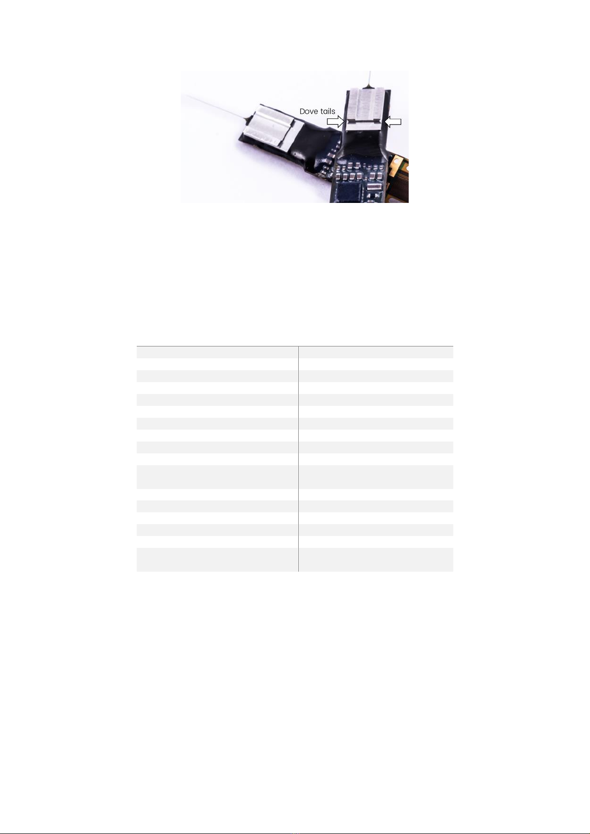
The probe base is covered either with a 300-µm-thick silicon spacer (8.5 3.9 mm) or aluminum metal
cap
10
(7.3 4.8 mm) with dedicated dovetail structures (Figure 6). Both probe covers serve primarily as
light-shields for the light-sensitive circuits in the probe base but also enable alignment and attachment
of compatible stereotactic insertion drives developed amongst others at HHMI Janelia Research
Campus.
10
Probes with metal cap are available as of June 2019.
NEUROPIXELS 1.0 USER MANUAL V1.0.5
14
Figure 6: Probes with stainless-steel cap featuring dedicated dovetail structures.
A black epoxy (EPO-TEK/H70E) encapsulates the probe perimeter and bond wires. The SMD
components are also coated with a conformal, hermetic coating (ELPEGUARD/SL 1307 FLZ-T). The probe
package with silicon spacer weighs 400 mg and the one with a metal cap 440 mg. The respective
thicknesses at the probe base are ~1.2 mm and ~1.8 mm for the two packages (Figure 4). Table 4
summarizes the package dimensions and properties.
Table 4: Probe package description
PACKAGE DESCRIPTION
WIDTH AT PROBE BASE
6.2 mm
WIDTH AT SMD BASE
7.2 mm
WIDTH OF SILICON SPACER
3.9 mm
WIDTH OF METAL CAP
4.8 mm
WIDTH OF FLEX
4.3 mm
LENGTH OF PROBE BASE
10.7 mm
LENGTH OF SMD BASE
12.2 mm
LENGTH OF SILICON SPACER
8.5 mm
LENGTH OF METAL CAP
7.3 mm
LENGTH OF FLEX
39.5 mm
THICKNESS AT PROBE BASE
~1.2 mm (w/ Si spacer)
~1.8 mm (w/ metal cap)
THICKNESS OF FLEX
80 µm
EXTERNAL REFERENCE INPUT
REF (multiple pads along flex)
GROUND INPUT
GND (multiple pads along flex)
BLACK EPOXY
EPO-TEK / H70E
CONFORMAL COATING OF SMD
ELPEGUARD / SL 1307 FLZ-T
WEIGHT
400 mg (w/ Si spacer)
440 mg (w/ metal cap)
NOTE: Please carefully read and follow the guidelines on soldering (Appendix B) before soldering
separate wires to the REF and GND input pads. It is advisable to have prior experience in soldering
before soldering to the Neuropixels probes.
NOTE: Please carefully read and follow the instructions on probe handling (Appendix A) and ESD
protection (Appendix C) prior to handling any Neuropixels system components. Familiarize yourself
with the probes by first handling and testing dummy probes which can be ordered separately.
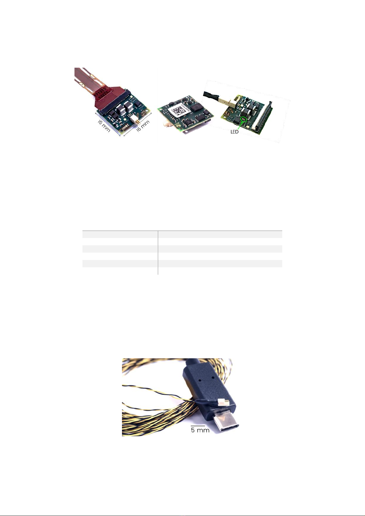
3.2 Headstage
The HS (Figure 7) is 16 15 mm and weighs 0.9 g. It contains several LDO regulators for power supply,
a serializer chip for communication to/from the PXIe acquisition module, and an EEPROM for
NEUROPIXELS 1.0 USER MANUAL V1.0.5
15
identification. A 45-pin FPC ZIF connector with a black latch connects to the probe (Figure 7). A 4-pin
Omnetics connector plugs into the 5-m long twisted-pair interface cable (Figure 8).
Figure 7: Left: Top side of a headstage connected to a probe flex. Center: Bottom side of a headstage with unique
serial ID. Right: Headstage connected to an interface cable.
A red status LED (Figure 7) indicates the correct functionality of the headstage. The LED can be enabled
and disabled using a dedicated API call. A HS EEPROM contains information on serial number (as printed
on the label), part number, PCB version and revision number. Table 5 summarizes the key headstage
specifications.
Table 5: Key headstage specifications
HEADSTAGE
SIZE
15 16 mm
WEIGHT
0.9 g
ZIF CONNECTOR
45-pin
CABLE CONNECTOR
4-pin (Omnetics)
LED INDICATOR
One red LED
MECHANICAL FIXTURES
Two mounting holes of 1 mm Ø
NOTE: Please carefully read and follow the instructions on ESD protection (Appendix C) prior to
handling any system components.
3.3 Interface Cable
The Neuropixels single twisted-pair interface cable (Figure 8) provides power from the PXIe acquisition
module to the HS and transfers control and neural data to/from the HS. The cable assembly weighs 5 g
(excl. USB-C connector) and consists of two 5-m long wire strands each having a diameter of 0.41 mm.
Figure 8: Twisted-pair interface cable with Omnetics-to-USB-C termination

NEUROPIXELS 1.0 USER MANUAL V1.0.5
16
The HS side of the cable is terminated with a 4-pin Omnetics connector. The PXIe module side is
terminated with a USB-C connector.
Table 6: Key cable specifications
TWISTED-PAIR DATA/POWER CABLE11
LENGTH
5 m
WEIGHT
5 g (excl. USB-C connector)
DIAMETER
0.41 0.82 mm
HEADSTAGE CONNECTOR
4-pin (Omnetics)
PXIE CARD CONNECTOR
USB-C
WIRE STRANDS
1 twisted pair
NOTE: Avoid repeated sharp bending of the cable (
≤
2 cm bending radius) as this may degrade cable
quality and signal integrity. Use the cable only with the Neuropixels PXIe acquisition module; do not
plug the cable into any other USB-C port as this may damage the cable.
3.4 PXIe Acquisition Module
The PXIe acquisition module (Figure 9) is a custom-made board with a deserializer chip and two FPGAs
12
for probe configuration, data acquisition and transmission to PC via a PCIe interface. It is compatible
with standard PXIe chassis, which must be purchased from other well-known third-party vendors such
as NI, Keysight or Adlink. Chassis recommendations are provided in Section 2.2 on page 7.
The module has 4 USB-C input ports thus allowing simultaneous connection and operation of up to 4
probes. Various trigger signals
13
can be configured to synchronize and use multiple PXIe modules and
thus probes simultaneously.
11
Custom cable assembly.
12
Xilinx ZYNQ and Xilinx Artix-7
13
A trigger line switch matrix and configurable sync clock are implemented. Various trigger signals can be programmed: SMA
connector, 7 trigger lines on the PXIe bus, user defined data or software trigger. Common trigger for multiple modules and/or
external instruments.
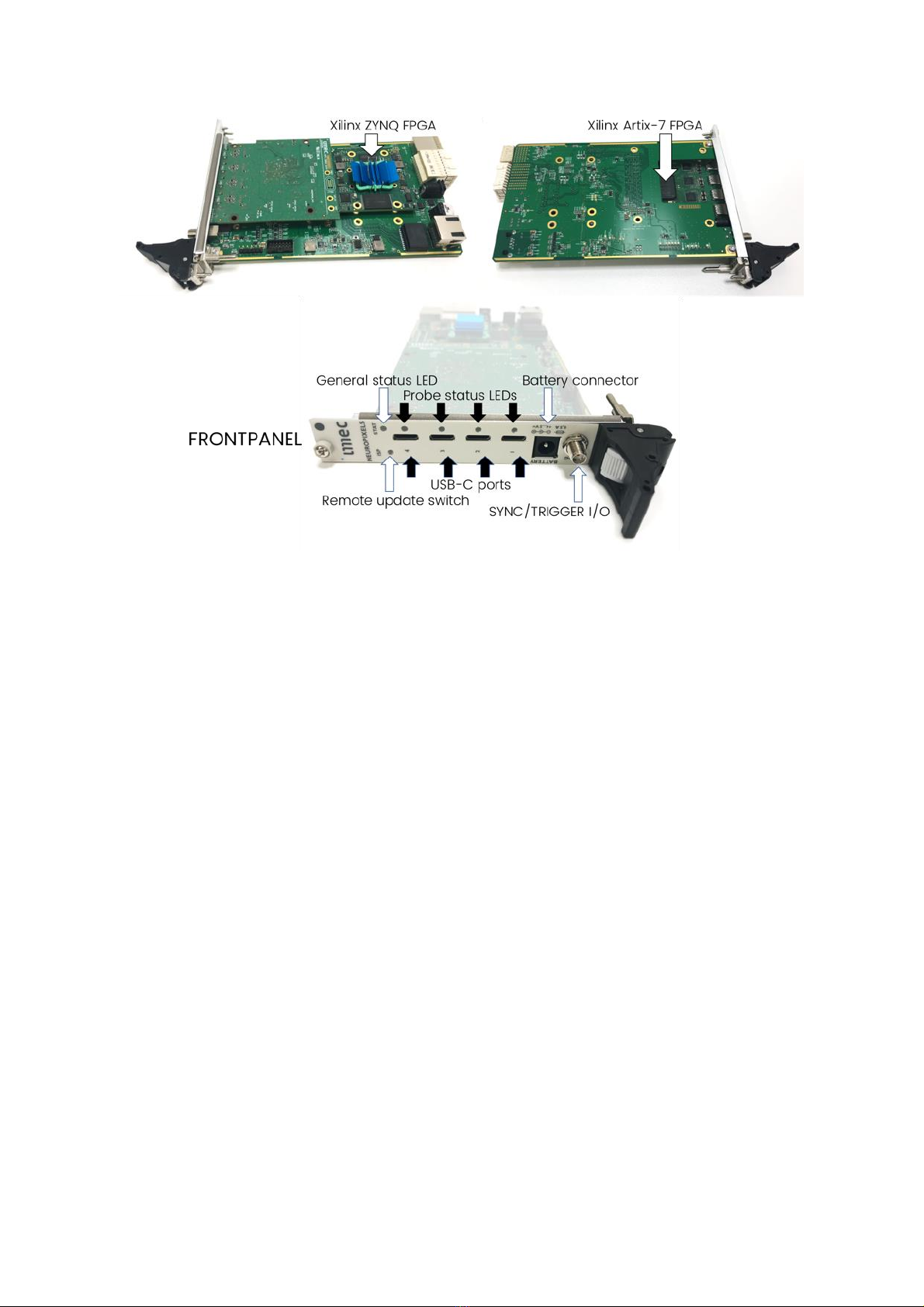
NEUROPIXELS 1.0 USER MANUAL V1.0.5
17
Figure 9: Top: PXIe acquisition module. Bottom: Front panel of the module.
The front panel of the PXIe acquisition module (Figure 9, bottom) contains the following connectors
and status LEDs:
•Four numbered USB-C ports allow connection of up to 4 probes. Interface cables can plug
into the USB-C port in either orientation.
•An LED next to each USB-C port indicates the status of the respective probe and HS:
oOff: No clock signal (from a probe) detected. This occurs if the power to the port is not
enabled, no probe is plugged into the port, or there is a faulty probe, HS, or cable.
oRed: The probe is powered on but not initialized.
oGreen: The probe is powered on and configured. This is the normal status during
operation of the probe.
oBlinking green: The probe is powered on but not correctly configured.
oBlue: An internal data emulator on the Artix-7 FPGA is active. The probe data is not used.
•A general status LED indicates the status of the PXIe module:
oOff: The Artix-7 FPGA is not powered, or the boot code is not loaded successfully.
oRed: Error status related to ZYNQ FPGA or PXIe bus.
oGreen: The Artix-7 FPGA is powered on and the boot code is loaded, waiting for a start
trigger to start transmitting neural data.
oBlue: The Artix-7 FPGA is triggered and is transmitting data to the ZYNQ FPGA.
oPurple: Combination of red and blue. Data is not read sufficiently fast by the PC. This
indicates data loss.
•A switch used for remote updates of the Artix-7 and ZYNQ FPGA boot codes.
•A battery connector to supply power to the probe and HS. The use of this connector is
optional. The hardware automatically detects if an external supply is connected and, if so,
switches the port supply from internal system supply to external supply. Connect a 4.0-to-5.0
V battery.
•A SYNC/TRIGGER I/O SMA connector:

NEUROPIXELS 1.0 USER MANUAL V1.0.5
18
oThis can serve as an input to connect an external digital trigger signal to start data
acquisition, or it can serve as an output to indicate the occurrence of an internal trigger
such as a software trigger, a user-defined data trigger, or a trigger from the PXI backplane
trigger bus (another PXIe acquisition module or card in the PXIe chassis).
oIt can serve as an input for an external SYNC signal, or it can serve as an output for an
internal SYNC signal. This SYNC signal is recorded with neural data across all probes
connected to the chassis and can be used to align neural data over different probes in
time. When used as an output for the internal trigger signal, a 1 ms pulse is generated on
the SMA. When used as an input, a pulse with a minimum width of 16 ns must be
connected.
oThe use and polarity of the SYNC/TRIGGER signal is configured using API functions. The
SYNC/TRIGGER line is compatible with 5.0 V logic signals. When used as an output
(software trigger or SYNC output), a high impedance load must be connected to the SMA
connector to observe the SYNC/TRIGGER output.
An EEPROM contains the serial number, part number, version and revision number of the PXIe
acquisition module. While the PXIe module contains hardware provisions for an ethernet connection,
neither FPGA code nor API currently support this functionality.
NOTE: Please carefully read and follow the instructions on ESD protection (Appendix C) prior to
handling any system components.
3.5 Headstage Test Dongle
The HS test dongle (HST) is a small test box (Figure 10) that plugs into the HS ZIF connector of a
headstage. Its purpose is to help verify the functionality of a HS. This is useful when e.g. neural data
seems corrupted or cannot be recorded or when a probe cannot be programmed correctly anymore.
Figure 10: Headstage test dongle with flex cable that plugs into the ZIF connector of a headstage.
Verifying the HS functionality is one of the first steps when identifying the root cause(s) for observed
failures. The HS tests will be integrated in the application software (Open Ephys, SpikeGLX). In case of
failure, the application can provide more detailed information about the exact source of the failure (e.g.
power supply, serial data link, clock signal, reset signals, etc. LEDs on the HST indicate status and result
of the HS tests. We recommend to always repeat the HS test also with an un-used, good HS to verify
that the failure is not related to other system components such as the interface cable.
NOTE: The API provides several built-in self-tests described in the Troubleshooting Section 5.3. These
can be implemented in the application software and help diagnose and debug potential hardware
failures along the entire signal chain from ASIC to PC.

NEUROPIXELS 1.0 USER MANUAL V1.0.5
19
NOTE: Liquids, metallic particles etc. might cause a short-circuit on the HS. Such short-circuits are
detected with the HST, except for 2 specific locations on the HS, which are indicated in yellow on the
figure below. If such a short would occur without being detected by the HST, the neural data recorded
by the probe will be corrupted on multiple channels.
Figure 11: Locations on the HS in which an electrical short-circuit cannot be detected.

NEUROPIXELS 1.0 USER MANUAL V1.0.5
20
4Installation and Configuration
This Chapter describes how to install and operate the Neuropixels Control System. Make sure you have
the following hardware components available:
•Third-party PXIe chassis + remote controller (see Section 2.2 for provider recommendations),
•PC with at least one PCIe slot (Gen 2 x8 or wider) (see Section 2.2 for additional hardware and
system requirements; also consult the requirements for the application software you intend to
use)
•Neuropixels PXIe acquisition module.
4.1 PXIe Chassis and Remote Controller
The first step is to install the third-party remote controller into your PXIe chassis. Here we will provide
you with some basic guidelines but do emphasize the need to follow the instructions and safety
information described in the user manuals of the chosen PXIe chassis and remote controller provider.
Follow the steps below to install the PXIe-8381 remote controller into the NI PXIe-1071 chassis and the
NI PCIe-8381 board into the PC:
1. Power-off the PXIe chassis, but leave the power cable plugged in to ground the chassis.
2. Identify a valid PXIe slot and remove the filler panel. The slot type on the chassis can be
identified by symbols next to the slot number, as shown in Figure 12. The PXIe-8381
remote control module must be plugged into the ‘PXIe Controller Slot’.
Figure 12: PXIe chassis slot symbols (source: ni.com).
3. Push the ejector handle down (Figure 13) by pressing the grey button (step 1) on the
handle and subsequently pushing the black handle (step 2) down.
Table of contents
Popular Laboratory Equipment manuals by other brands

Microscan
Microscan MicroHAWK 98-9000077-01 Accessory guide

Boekel
Boekel FLASK DANCER operating instructions

Applied Biosystems
Applied Biosystems 7900HT user guide

Leica
Leica HistoCore Arcadia C Instructions for use

DIGISYSTEM
DIGISYSTEM RM-501 instruction manual

Agilent Technologies
Agilent Technologies 1260 Infinity Service manual


