Axis 8122 DC 30W Midspan User manual

Safety information
Installation and removal of the AXIS
T8122 DC 30W Midspan must be
carried out by qualified personnel
only.
• DC Power Cable Set:
• The power cable must have regulatory
agency approval for the country in which
it is used (for example, UL, CSA, VDE).
• The power cable must be rated for a
minimum current capacity of 3 amps.
• The DC power source must be near the AXIS
Midspan and easily accessible. You can
remove DC power from the AXIS Midspan by
disconnecting the DC power cable from either
the power source or the AXIS Midspan.
• The AXIS Midspan data and data/power
interfaces are qualified as SELV (Safety Extra-
Low Voltage) circuits according to IEC 60950.
These interfaces can only be connected to
SELV interfaces on other equipment.
WARNING!
• Read the instructions before connecting
the Midspan to its power source.
• Follow basic safety measures while
connecting Midspan to power source.
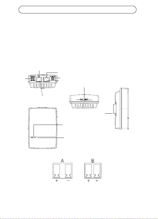
• The GND pin on the 45-57V DC contact is
an isolated GND; do NOT connect it to
the GND-shield on the RJ45.
• Voltage mismatch can cause equipment
damage and may pose a fire hazard. If
voltage indicated on the label is different
from power source voltage, do not
connect Midspan to this power source.
• This product relies on the building
installation for short-circuit (over
current) protection. Ensure that the
power source is protected by a fuse or
circuit breaker.
• The Midspan "Data In" and "Data & Power
Out" ports are shielded RJ-45 data
sockets. They cannot be used as Plain Old
Telephone Service (POTS) telephone
sockets. Only RJ-45 data connectors may
be connected to these sockets.
Notice:
In keeping with its policy to improve products,
as new technology, components, software, and
firmware become available, Axis reserves the
right to change specifications without prior
notice.
Technical support (for Midspan and
Splitters)
Should you require technical assistance, please
contact your Axis reseller. If your questions
cannot be answered immediately, the reseller
will forward your queries through the
appropriate channels to ensure rapid response. If
you are connected to the Internet, you can:
• Download user documentation
• Find answers to resolved problems in the FAQ
database
• Search by product, category, or phrases
• Report problems to Axis support by logging in
to your private support area
• Visit Axis Support at www.axis.com/techsup/
Electromagnetic Compatibility (EMC)
This equipment generates, uses and can radiate
radio frequency energy and, if not installed and
used in accordance with the instructions, may
cause harmful interference to radio
communications. However, there is no
guarantee that interference will not occur in a
particular installation.
If this equipment does cause harmful
interference to radio or television reception,
which can be determined by turning the
equipment off and on, the user is encouraged to
try to correct the interference by one or more of
the following measures: Re-orient or relocate
the receiving antenna. Increase the separation
between the equipment and receiver. Connect
the equipment to an outlet on a different circuit
to the receiver. Consult your dealer or an
experienced radio/TV technician for help.
Shielded (STP) network cables must be used with
this unit to ensure compliance with EMC
standards.
USA - This equipment has been tested and
found to comply with the limits for a Class B
computing device pursuant to Subpart B of Part
15 of FCC rules, which are designed to provide
reasonable protection against such interference
when operated in a commercial environment.
Operation of this equipment in a residential area
is likely to cause interference, in which case the
user at his/her own expense will be required to
take whatever measures may be required to
correct the interference.
Canada - This Class B digital apparatus
complies with Canadian ICES-003.
Europe - This digital equipment fulfills
the requirements for radiated emission

according to limit B of EN55022, and the
requirements for immunity according to
EN55024 residential and commercial industry.
Japan - This is a class B product based on the
standard of the Voluntary Control Council for
Interference from Information Technology
Equipment (VCCI). If this is used near a radio or
television receiver in a domestic environment, it
may cause radio interference. Install and use the
equipment according to the instruction manual.
Australia - This electronic device meets the
requirements of the Radio communications
(Electromagnetic Compatibility) Standard AS/
NZS CISPR22.
WEEE Directive
The European Union has enacted a
Directive 2002/96/EC on Waste
Electrical and Electronic Equipment
(WEEE Directive). This directive is
applicable in the European Union
member states.
The WEEE marking on this product
(see right) or its documentation indicates that
the product must not be disposed off together
with household waste. To prevent possible harm
to human health and/or the environment, the
product must be disposed off in an approved and
environmentally safe recycling process. For
further information on how to dispose off this
product correctly, contact the product supplier,
or the local authority responsible for waste
disposal in your area.
Business users should contact the product
supplier for information on how to dispose off
this product correctly. This product should not
be mixed with other commercial waste. For more
information, visit www.axis.com/techsup/


AXIS T8122 DC 30W Midspan Page 5
ENGLISH
AXIS T8122 DC 30W Midspan
Package contents
Functions and features
The AXIS T8122 DC 30W Midspan injects 52V DC power into the spare
pairs of the Ethernet cabling. It complies with both IEEE802.3af and
IEEE802.3at standards. These power levels allow a new range of
Ethernet-based applications such as PTZ Cameras to use the Midspan.
Preliminary steps
• Ensure DC power is applied to the AXIS T8122, using an operational
DC cable with appropriate ground connection.
• Ensure that output Ethernet cable is connected to the Data & Power
Out port.
• Verify that a power-ready Ethernet compatible device or splitter is
connected.
Note:
Do not use a cross over cable between the AXIS T8122 output port
and the powered device.
AXIS Midspan AXIS T8122 DC 30W Midspan
Power connections Terminal blocks
Printed material Installation guide (this document)
Warranty document

Page 6 AXIS T8122 DC 30W Midspan
Installation
1. Connect the AXIS T8122 to a DC outlet (12-24V DC / 45-57V DC).
2. Connect the unit Data In jack (In) to your remote Ethernet network
switch using a shielded Ethernet cable.
3. Connect the Data & Power Out jack (Out) to your Axis splitter or
camera, using a shielded Ethernet cable.
Input Input
Camera/splitters
Ethernet
Data and Power out
Data in
Port connectivity
indicator
DC Input connectivity
indicator
Power switch
DIN Rail
30W 15W
45-57V DC 12-24V DC
AB

AXIS T8122 DC 30W Midspan Page 7
ENGLISH
Power switch - Before the unit is powered on, the power switch has to be
set in the correct position.
• Position 1 (30W): Use this setting if an 802.3at PoE camera is con-
nected to the midspan and the power source can deliver a minimum
of 40W.
• Use this setting if an 802.3af PoE camera is connected to the midspan
and the power source can deliver a minimum of 20W.
CAUTION!
The GND pin on the 45-57V DC contact is an isolated GND; do NOT
connect it to the GND-shield on the RJ45.
Indicators
LED Color Indication
Port Unlit No camera connected
Steady green Camera connected, normal behavior 802.3af
(15W)
Steady yellow Camera connected, normal behavior 802.3at
(30W)
Green/yellow 1 Hz
blinking
Over current or short circuit condition on the
port
Green/yellow 4 Hz
blinking
PSE input voltage out of range or other
internal fault
DC
input
Steady green DC power connected

Page 8 AXIS T8122 DC 30W Midspan
Mounting instructions
The AXIS T8122 may be wall or bench mounted using the rear side holes.
It can also be mounted on a DIN rail.
Note the following before mounting the AXIS T8122 to a fixed location:
• Do not cover the midspan or block the airflow to the product with any
foreign object. Keep the midspan away from excessive heat and
humidity, and free from vibration and dust.
• Ensure that the cable length from the Ethernet network source to
your Axis video product does not exceed 100 meters (333 feet). See
page 10 for information on cable lengths. The midspan is not a
repeater and does not amplify the Ethernet data signal.
• Use a splitter if required, but ensure that the splitter is connected
close to your Axis video product and not to the Midspan.
• There is no "on-off" switch; simply plug the AXIS T8122 into a DC
power outlet.
To mount:
1. Install two screws vertically at a distance of 65 mm
(2.5”) on the wall or shelf.
2. Align the AXIS T8122 mounting slots to capture the
surface screws
A 6 to 7 mm (0.23" to 0.27")
B max 2.5 mm
C 2 mm to 3 mm (0.059" to 0.098")
D 3.0 mm (0.12")
A
B
D
c

AXIS T8122 DC 30W Midspan Page 9
ENGLISH
Specifications
Environmental
Electrical
Mode Temperature Humidity
Operating -20 to 65°C
-4 to 149°F
max 95% (non-condensing)
Storage -40 to 74°C
-24 to 158°F
DC Input voltage 1
DC Input voltage 2
12 to 24 V DC (max. 40 W)
45 to 57 V DC (max. 35 W)
Input current Max. 3A @ 12-24V DC
Max. 0.7A @ 45-57V DC
Maximum Available
Output Power
52V DC @ 12-24V DC in (max. 30W)
57V DC @ 45-57V DC in (max. 30W)
Nominal Output
Voltage
51V DC @ 12-24V DC
0.5V lower then input voltage @ 45-57V DC
Compliable Ethernet
cable lengths
When an 802.3af device is powered, all cables up to 100m
are compliable.
See table below when an 802.3at device is powered.

Page 10 AXIS T8122 DC 30W Midspan
Maximum cable length between network switch and powered device
When the unit is powered through the 12-24V DC input, the maximum
length of network cable is: 70 m @ Cat5 and 100 m @ Cat5e/6.
Ethernet interface
CAUTION!
The GND pin on the 45-57V DC contact is an isolated GND; do NOT
connect it to the GND-shield on the RJ45.
Input (Data In): Shielded RJ-45 EIA 568A and 568B
Output (Data &
Power Out):
Shielded RJ-45 EIA 568A and 568B
Wiring Data provided over pairs 1/2 and 3/6 for 10/100
Ethernet
Power over spare pairs 4/5 (+) and 7/8 (-)
Network cable Shielded category 5 (or higher)
Using a Cat 5e/6 is recommended while powering an
802.3at device.
Input voltage
Max cable
length between
network switch
and powered
device in meters
Cat5e/6
Cat5

AXIS T8122 DC 30W Midspan Page 11
ENGLISH
Troubleshooting
Symptom Corrective steps
Midspan does
not power up
1. Verify that an approved power cable is used.
2. Verify that the voltage at the power inlet is between
12-24V DC for Input voltage 1 and between 45-57V DC
for Input voltage 2.
3. Remove and re-apply power to the device and check
the indicators during power up sequence.
A port indicator
is not lit and the
PD (powered
device) does not
operate
1. The Midspan did not detect a PD; and the port is not
enabled.
2. Verify that the PD is designed for PoE operation.
3. Verify that you are using a standard Category 5/5e/6,
straight-wired cable, with four pairs.
4. If there is an external PoE device connected, replace it
to verify that it is functioning properly.
5. Ensure that the input Ethernet cable is connected to
the Data In port.
6. Verify that the PD is connected to the Data & Power
port.
7. Try to reconnect the same PD into a different Midspan.
If it works, there is probably a faulty port or RJ-45
connection.
8. Verify that there is no shortcut over any of the twisted
pair cables or over the RJ45 connectors.

Page 12 AXIS T8122 DC 30W Midspan
The end device
operates, but
there is no
data link
1. Verify that the port indicator on the front panel is
continuously lit.
2. If an external PoE device is in use, replace it with a
good PoE device.
3. Verify that for this link, you are using standard UTP/FTP
Category 5 straight (non-crossover) cabling, with all
four pairs.
4. Verify that the Ethernet cable length is less than 100
meters (333 feet) from the Ethernet source to the
powered device. See Maximum cable length between
network switch and powered device, on page 10.
5. Try to reconnect the same PD into a different Midspan.
If it works, there is probably a faulty port or RJ-45
connection.

Injecteur AXIS T8122 DC 30W Page 13
FRANÇAIS
Injecteur AXIS T8122 DC 30W
Contenu de l'emballage
Fonctions et caractéristiques
Votre Injecteur AXIS T8122 DC 30W envoie une puissance de 52 V CC
dans les paires inutilisées du câblage Ethernet. Il est conforme aux
normes IEEE802.3af et IEEE802.3at. Ces niveaux de puissance offrent
une nouvelle gamme d'applications en réseau telles que les caméras PTZ
en utilisant l'injecteur.
Étapes préliminaires
• Vérifiez que votre AXIS T8122 est raccordé à un câble CC en bon état
de fonctionnement et correctement mis à la terre.
• Vérifiez que le câble Ethernet de sortie est branché sur le port de
données et d'alimentation de sortie.
• Vérifiez qu'un périphérique ou qu'un séparateur compatible Ethernet
prêt à être branché est connecté.
Remarque :
N'utilisez pas de câble simulateur de modem entre le port de sortie
de votre AXIS T8122 et le périphérique sous tension.
Injecteur AXIS Injecteur AXIS T8122 DC 30W
Connexions d'alimentation Blocs terminaux
Documentation Guide d'installation (le présent document)
Garantie

Page 14 Injecteur AXIS T8122 DC 30W
Installation
1. Branchez votre AXIS T8122 sur une prise CC (12-24 V CC/45-
57 V CC).
2. Branchez le connecteur de données d'entrée (entrée) au
commutateur réseau Ethernet distant à l'aide d'un câble Ethernet
blindé.
3. Branchez le connecteur de données et d'alimentation de sortie
(sortie) sur votre séparateur ou caméra Axis à l'aide d'un câble
Ethernet blindé.
Entrée Entrée
Caméra/séparateurs
Ethernet
Données et alimentation de sortie
Données d'entrée
Indicateur de connexion du port
indicateur
Connectivité d'entrée CC
indicateur
Interrupteur
Rail DIN
30 W 15 W
45-57 V CC 12-24 V CC
B
A

Injecteur AXIS T8122 DC 30W Page 15
FRANÇAIS
Interrupteur - Avant d'allumer l'unité, vous devez mettre le bouton
d'alimentation sur la bonne position.
• Position 1 (30 W) : utilisez ce réglage si une caméra 802.3at PoE est
reliée à l'injecteur et si la source d'alimentation peut fournir au moins
40 W.
• Utilisez ce réglage si une caméra 802.3af PoE est reliée à l'injecteur et
si la source d'alimentation peut fournir au moins 20 W.
ATTENTION !
La broche GND sur le contact 45-57 V CC est une broche GND isolée.
Vous ne devez PAS la relier au blindage GND du RJ45.
Indicateurs
DEL Couleur Indication
Port Éteint Aucune caméra connectée
Vert continu Caméra 802.3af connectée, fonctionnement
normal (15 W)
Jaune continu Caméra 802.3at connectée, fonctionnement
normal (30 W)
Vert/jaune 1 Hz
clignotant
Surintensité ou court-circuit sur le port
Vert/jaune 4 Hz
clignotant
Tension d'entrée PSE hors limites ou autre
défaillance interne
Entrée
CC
Vert continu Alimentation CC connectée

Page 16 Injecteur AXIS T8122 DC 30W
Instructions de montage
Votre AXIS T8122 peut être fixé au mur ou monté sur banc à l'aide des
trous situés au dos de l'appareil. Il peut également être monté sur un rail
DIN.
Prennez note de ce qui suit avant de poser votre AXIS T8122 à un endroit
fixe :
• Ne recouvrez pas l'injecteur ou ne bloquez pas son système d'aération
par des corps étrangers. Conservez l'injecteur à l'abri des excès de la
chaleur et de l'humidité, des vibrations et de la poussière.
• Veillez à ce que la longueur de câble entre la source du réseau
Ethernet et votre produit vidéo Axis ne dépasse pas 100 mètres (333
pieds). Reportez-vous à la page 18 pour plus d'informations sur les
longueurs de câble. L'injecteur n'est pas un répéteur et il n'amplifie
pas le signal des données Ethernet.
• Utilisez un diviseur si vous le souhaitez, en veillant à ce qu'il soit
branché à proximité de votre produit vidéo Axis et non sur l'injecteur.
• Il n'y a pas de bouton "marche/arrêt". Il vous suffit de brancher votre
AXIS T8122 à une prise de courant CC.
Pour monter :
1. Placez deux vis à la verticale à une distance de 65 mm
(2,5") sur le mur ou l'étagère.
2. Alignez les fentes de montage de votre AXIS T8122
pour incruster les vis de surface
A 6 à 7 mm (0,23" à 0,27")
Bmax.2,5mm
C 2 mm à 3 mm (0,059" à 0,098")
D 3,0 mm (0,12")
A
B
D
c

Injecteur AXIS T8122 DC 30W Page 17
FRANÇAIS
Caractéristiques techniques
Conditions d'utilisation
Électrique
Mode Température Humidité
En fonctionnement -20 à 65 °C
-4 à 149 °F
95 % max. sans
condensation
Stockage -40 à 74 °C
-24 à 158 °F
Tension
d'entrée CC 1
Tension
d'entrée CC 2
12 à 24 V CC (max. 40 W)
45 à 57 V CC (max. 35 W)
Courant d'entrée Max. 3 A à 12-24 V CC
Max. 0,7 A à 45-57 V CC
Puissance de sortie
disponible
maximum
52 V CC à 12-24 V CC en entrée (max. 30 W)
57 V CC à 45-57 V CC en entrée (max. 30 W)
Tension de sortie
nominale
51 V CC à 12-24 V CC
0,5 V de moins que la tension d'entrée à 45-57 V CC
Longueurs de câble
Ethernet conformes
Lorsqu'un dispositif 802.3af est sous tension, tous les
câbles de 100 mètres maximum sont conformes.
Reportez-vous au tableau ci-dessous dans le cas où un
dispositif 802.3at est sous tension.

Page 18 Injecteur AXIS T8122 DC 30W
Longueur de câble maximum entre le commutateur réseau et le
dispositif sous tension
Lorsque l'unité est alimentée par une entrée 12-24 V CC, la longueur
maximum du câble réseau est : 70 m à Cat5 et 100 m à Cat5e/6.
Interface Ethernet
ATTENTION !
La broche GND sur le contact 45-57 V CC est une broche GND isolée.
Vous ne devez PAS la relier au blindage GND du RJ45.
Entrée (données
d'entrée) :
RJ-45 EIA 568A et 568B blindé
Sortie (données et
puissance de sortie) :
RJ-45 EIA 568A et 568B blindé
Câblage Données fournies sur les paires 1/2 et 3/6 pour 10/100
Ethernet
Alimentation sur les paires inutilisées 4/5 (+) et 7/8 (-)
Câble réseau Catégorie 5 (ou supérieure) blindée
Il est recommandé d'utiliser une Cat5e/6 pour alimenter
un dispositif 802.3at.
Tension d'entrée
Longueur de câble
maximum entre
le commutateur réseau
et le dispositif
sous tension en mètres
Cat5e/6
Cat5

Injecteur AXIS T8122 DC 30W Page 19
FRANÇAIS
Dépannage
Symptôme Correction
L'injecteur ne se
met pas sous
tension.
1. Vérifiez qu'un câble d'alimentation approuvé est
utilisé.
2. Vérifiez que la tension à l'arrivée se situe entre
12 et 24 V CC pour la tension d'entrée 1 et entre
45 et 57 V CC pour la tension d'entrée 2.
3. Mettez l'injecteur hors tension et rallumez-le en
vérifiant les indicateurs pendant la mise sous tension.
Un indicateur de
port est éteint et
le périphérique
sous tension ne
fonctionne pas.
1. L'injecteur n'a pas détecté de périphérique sous
tension. Le port est donc désactivé.
2. Vérifiez que le périphérique sous tension prend en
charge la technologie PoE.
3. Vérifiez que vous utilisez un câble à fils droits ordinaire
de catégorie 5/5e/6 à quatre paires.
4. Si un dispositif PoE externe est utilisé, remplacez-le
pour vous assurer qu'il fonctionne correctement.
5. Vérifiez que le câble Ethernet d'entrée est branché sur
le port de données d'entrée.
6. Vérifiez que le périphérique sous tension est branché
sur le port de données et d'alimentation.
7. Essayez de rebrancher le périphérique sous tension sur
un injecteur différent. Si cela fonctionne, il est probable
que le connecteur RJ-45 soit défectueux.
8. Vérifiez qu'il n'y a pas de court-circuit sur les câbles à
paires torsadées ni sur les connecteurs RJ45.

Page 20 Injecteur AXIS T8122 DC 30W
Lepériphérique
final
fonctionne,
mais il n'y a
pas de liaison
de données.
1. Vérifiez que l'indicateur de port à l'avant de l'appareil
est allumé en continu.
2. Si un dispositif PoE externe est utilisé, remplacez-le par
un dispositif PoE que vous savez en bon état de
fonctionnement.
3. Vérifiez que, pour cette liaison, vous utilisez un câble
droit UTP/FTP ordinaire de catégorie 5 (et non un câble
simulateur de modem), avec les quatre paires.
4. Vérifiez que le câble Ethernet ne fait pas plus de
100 mètres (333 pieds) de long entre la source Ethernet
et le périphérique sous tension. Reportez-vous à
Longueur de câble maximum entre le commutateur
réseau et le dispositif sous tension, page 18.
5. Essayez de rebrancher le périphérique sous tension sur
un injecteur différent. Si cela fonctionne, il est probable
que le connecteur RJ-45 soit défectueux.
Table of contents
Languages:
Other Axis Laboratory Equipment manuals
Popular Laboratory Equipment manuals by other brands

Shodex
Shodex IEC SP-FT 4A Operation manual

ThermoFisher Scientific
ThermoFisher Scientific TX-200 instruction manual

Agilent Technologies
Agilent Technologies Cary 3500 user guide

Awareness Technology
Awareness Technology CHROMATE Operator's manual

Labnet
Labnet Spectrafuge 16M user manual

StarTech.com
StarTech.com POEINJ1G instruction manual

Fritsch
Fritsch PULVERISETTE 7 premium line operating instructions

Thermo Scientific
Thermo Scientific AquaSensors AquaTrace user guide

NACALAI TESQUE
NACALAI TESQUE COSMOSIL HPLC quick start guide

Sigma
Sigma 8K operating manual

Gilson
Gilson Pipetman Fixed user guide

NOVAPRO
NOVAPRO CRYSTE PURIFUME DUCTLRESS operating instructions