Imer Group ES 150 N Guide

IMER INTERNATIONAL S.p.A.
Via Salceto, 55 - 53036 POGGIBONSI (SI) -(ITALY)
Tel. 0577 97341 - Fax 0577 983304
www.imergroup.com
ES 150 N
( 1140909 110V 50Hz )
3231719 (10/2013)
ELEVATORE
Manuale uso manutenzione e ricambi
HOIST
Operating,maintenance,spare parts manual

ES 150 N - 110V 50Hz
2
IMER INTERNATIONAL S.p.A.
Particolare attenzione deve essere fatta alle avvertenze contrassegnate con questo simbolo :
Special attention must be given to warnings with this symbol:
LIVELLA
WATER LEVEL
1FUNE ACCIAIO STEEL ROPE
2GANCIO HOOK
3TAMBURO DRUM
4MOTORE ELETTRICO
AUTOFRENENTE
ELECTRIC BRAKE
MOTOR
5QUADRO ELETTRICO ELECTRIC PANEL
6RIDUTTORE GEAR BOX
7TELAIO ROTARY SUPPORT
FRAME
8PULSANTIERA PENDANT CONTROL
9LEVA FINECORSA
SALITA LIMIT SWITCH LEVER
10 CONTRAPPESO COUNTERWEIGHT
11 LEVA BLOCCAGGIO
TELAIO
FRAME LOCKING
LEVER
12 PERNO SOSTEGNO SUPPORT PIN
13 COPIGLIA SPLIT PIN
Fig. 1
DATI TECNICI TECHNICAL DATA
Portata max Max capacity kg 150
Velocità media di
sollevamento Lifting speed m / 1' 19
Altezza max di
lavoro Max working height m30
Alimentazione Nom. voltage V / Hz 110 / 50
Potenza motore Motor power KW 0,75
Giri motore R.P.M. n° / 1' 1.360
Assorbimento Nom. current A14
Tipo di servizio Duty type S3 50%
Livello di emissione
sonora LwA (EN ISO
3744)
Noise emission
level LwA (EN
ISO 3744)
dB 79
Livello di pressione
sonora LpA a 1,5 m
Level of noise pres-
sure LpA - 1,5m dB <70
Peso macchina Machine weight kg 39
Ingombro per
l'imballo Packing dimensions mm 820x350x550
Norme di progetto Design standards
FEM 1.001, UNI-ISO 4301-4308-2408, UNI 7670-9466, EN
60204-1, EN 60204-32, EN 60034-1, ISO 6336-1/-2

3
IMER INTERNATIONAL S.p.A.
ES 150 N - 110V 50Hz
Caro cliente,
ci complimentiamo per il suo acquisto dell’elevatore IMER, risultato di
anni di esperienza: è una macchina di massima affidabilità e dotata
di soluzioni tecniche innovative.
- OPERARE IN SICUREZZA: É fondamentale ai fini della
sicurezza leggere attentamente le seguenti istruzioni.
Il presente manuale di USO E MANUTENZIONE deve essere
custodito dal responsabile di cantiere, sempre disponibile per la
consultazione.
Il manuale è da considerarsi parte della macchina e deve essere
conservato per futuri riferimenti (EN ISO 12100-2) no alla distruzione
della macchina stessa. In caso di danneggiamento o smarrimento
potrà essere richiesto al costruttore un nuovo esemplare.
Il manuale fornisce istruzioni per l’installazione, l’uso, la manutenzione
dell'apparecchio con importanti avvertenze.
Comunque è da ritenersi indispensabile una adeguata esperienza e
conoscenza della macchina da parte del montatore e dell’ utilizzatore.
Afnché sia possibile garantire la sicurezza dell’operatore, la sicurezza
di funzionamento e una lunga durata dell’apparecchio, devono essere
rispettate le istruzioni del manuale, unitamente alle norme di sicurezza
e prevenzione degli infortuni sul lavoro secondo la legislazione vigente
(uso di calzature e abbigliamento adeguati, uso di elmetti, di cinture
di sicurezza, predisposizione di parapetti prospicienti il vuoto, ecc.).
- É vietato apportare modifiche di qualsiasi natura alla
struttura metallica o impiantistica della macchina.
IMER INTERNATIONAL declina ogni responsabilità in caso di non
osservanza delle leggi che regolano l’uso di apparecchi di solleva-
mento, in particolare: uso improprio, difetti di alimentazione, carenza
di manutenzione, modiche non autorizzate, manomissioni e/o dan-
neggiamenti, inosservanza parziale o totale delle istruzioni contenute
in questo manuale.
-
IMER INTERNATIONAL ha il diritto di modificare le
caratteristiche dell'elevatore e/o i contenuti del presente
manuale, senza l'obbligo di aggiornare la macchina e/o i
manuali precedenti.
1. DESCRIZIONE GENERALE
- Avvertenza: Operare con una macchina di sollevamento
richiede grande attenzione e perizia, il comando può essere
affidato solo a personale esperto o che abbia ricevuto le neces-
sarie istruzioni.
- 1) La macchina è concepita per il sollevamento di materiali
e per essere utilizzata nei cantieri di costruzioni edili.
- 2) É vietato l’uso per il sollevamento di persone e/o di
animali.
- 3) Non deve essere utilizzato in ambienti ove esista il pe-
ricolo d’esplosioni o incendio o in ambienti di scavi sotterranei.
La macchina è costituita essenzialmente da (g.1):
- Tamburo montato sull’albero del riduttore (rif.3) da una fune
metallica (rif.1) da un gancio di sollevamento (rif.2) e contrappeso
(rif.10).
- Motoriduttore composto da un motore elettrico autofrenante (rif.
4) e riduttore ad ingranaggi a bagno d’olio (rif. 6).
- Impianto elettrico (rif. 5).
- Leva di comando ne corsa salita (rif. 9).
- Telaio portante girevole (rif.7), leva di bloccaggio telaio (rif. 11).
- Pulsantiera da 1,5 m a comando diretto a tre pulsanti (rif.8).
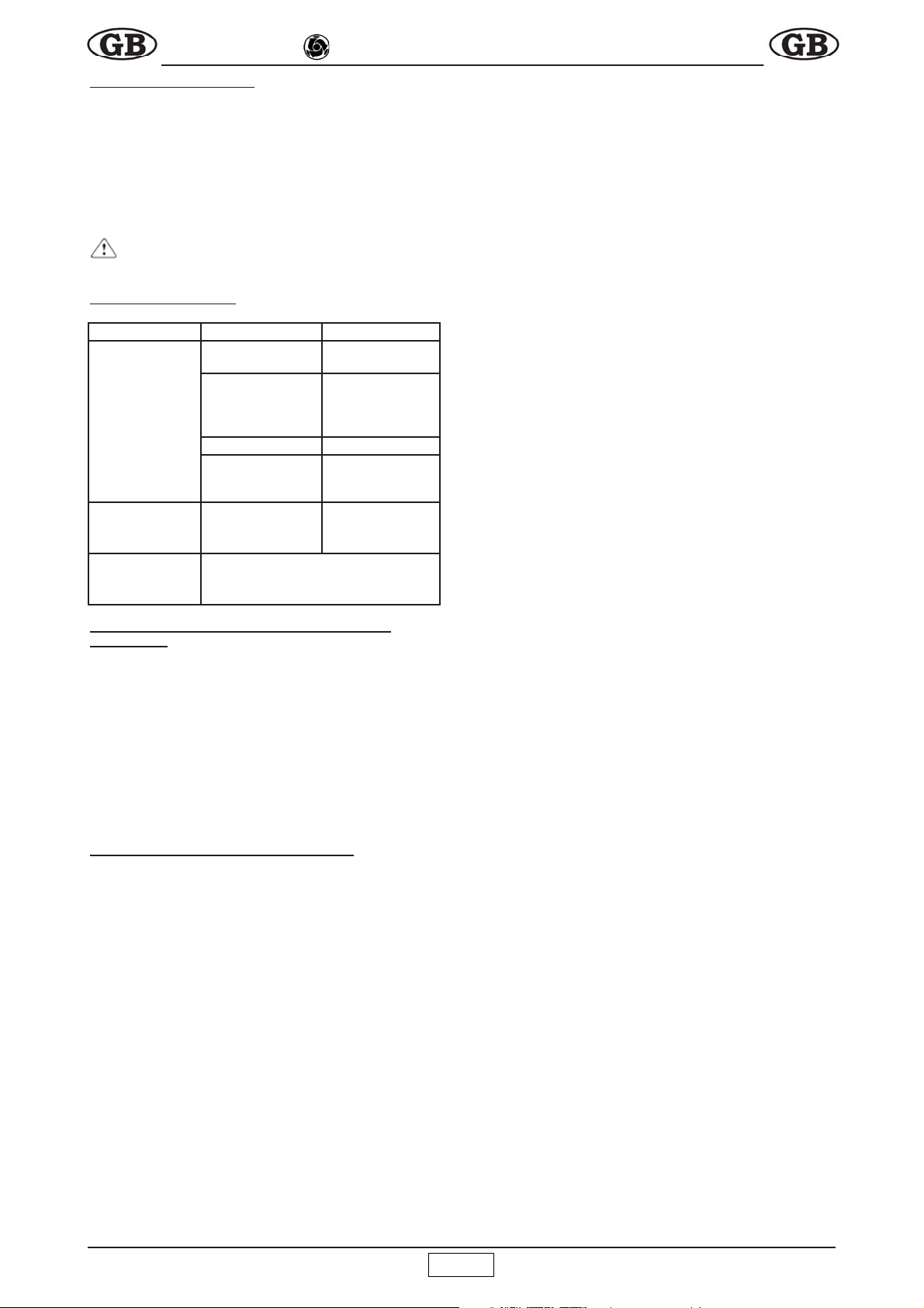
2. STRUTTURE DI SUPPORTO IMER PER L’ ELEVATORE
La struttura su cui l’elevatore viene applicato deve essere in grado di
sopportare le sollecitazioni indicate in g. 2, che si generano durante
il funzionamento.
La forza di 300N è perpendicolare a quella di 4000N. Poichè l' ele-
vatore può ruotare sui perni di sostegno, tali forze devono essere
vericate in tutte le posizioni che può assumere l'elevatore.
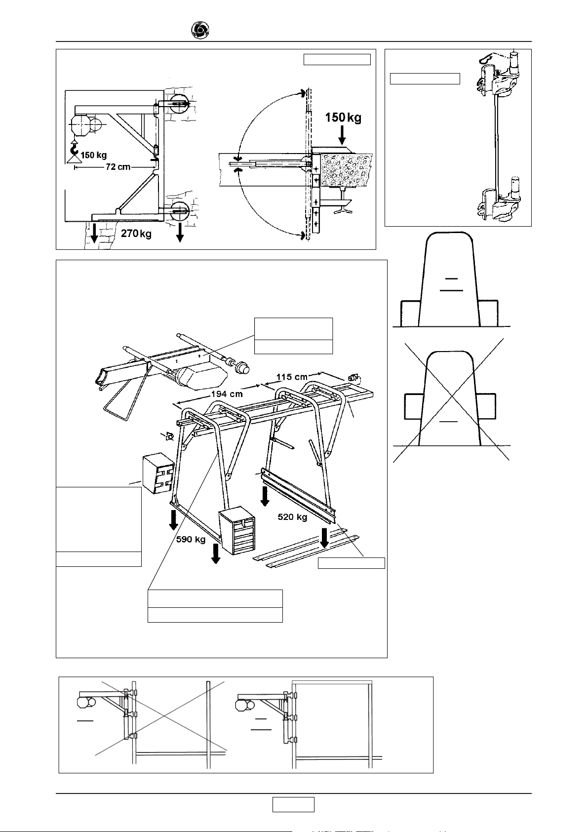
IMER dispone di una ampia scelta di supporti, rappresentati in gura
7 - 8 - 9 - 10 - 11 -12 e 13, previsti per le diverse applicazioni di can-
tiere, progettati in modo da trasmettere idoneamente alle strutture
questi carichi.
- ATTENZIONE
La dichiarazione CE di conformità allegata al presente manuale, è
valida solo se vengono utilizzati tutti componenti di costruzione
IMER (elevatore e relative strutture di supporto).
Se questa condizione non è rispettata, tale dichiarazione è valida
solo per l'elevatore.
Chi esegue l’installazione dovrà compilare una nuova dichia-
razione CE di conformità, dopo aver verificato tutti i requisiti
contenuti nella Direttiva Macchine 2006/42/CE per l'insieme
dell'elevatore e supporto.
Le forze, indicate agli appoggi di ciascun supporto, dovranno essere
considerate nel calcolo di verica delle strutture di sostegno (ponteggi,
terrazze, softti, ecc.) effettuato da tecnico competente.
In caso di applicazione dell’elevatore su ponteggio, questo deve
essere opportunamente controventato (vedere g. 14).
Per l’installazione dei diversi supporti, seguire le istruzioni di cui
ciascuno è fornito.
Nel caso si utilizzino dei supporti con portata diversa dall’elevatore,
sull’insieme dell’apparecchio installato dovrà essere afssa, ben
visibile la portata ammissibile in funzione dell’elemento più critico
del sistema.
2.1 PREDISPOSIZIONE DEL POSTO DI LAVORO
- Il lato dell’ apertura di accesso del carico al piano deve
essere protetto con un parapetto di altezza superiore a 1m ed
arresto al piede.
- Accertarsi che la corsa di lavoro sia sgombra per tutta l’altezza e
prendere le precauzioni necessarie perché nessuno possa sporgersi
dai piani intermedi.
- delimitare l’ area di carico inferiore perché nessuno possa sostarvi
durante il sollevamento.
3. MONTAGGIO (fig.1)
1) Il montaggio dell’elevatore, così come il suo utilizzo, richiede per-
sonale esperto o che abbia ricevuto le necessarie istruzioni.
Dato il peso dell’ elevatore, devono essere impiegati un numero
di operatori tali da non creare situazioni di pericolo durante il suo
trasporto ed installazione.
2) L’altezza massima di lavoro (30m) è quella relativa alla posizione
del motoriduttore corrispondente al perno superiore del supporto.
3) Posizionare il supporto sulla struttura dell’edicio, vericare l’alli-
neamento verticale dei perni di sostegno (rif.10) quindi, sollevando la
leva di bloccaggio (rif.11) inserire le boccole del telaio portante (7) sui
perni ed applicare la copiglia di sicurezza
(rif.13) antislamento.
4) Nel caso di montaggio su supporto a
cavalletto, ssare il telaio (7) al carrello
mediante i fori di fissaggio previsti (rif.
g.13) utilizzando viti e dadi autobloccanti.
Seguire per il resto le istruzioni fornite con
il cavalletto.
5) La pulsantiera è dotata di tre pulsanti
(g. 3):
nero = discesa
bianco = salita
rosso = arresto in caso d’ emergenza.
6) Liberare il gancio.
4. ALLACCIAMENTO ALLA RETE ELETTRICA
- Vericare che la tensione risulti conforme ai dati di targa della
macchina.
- Vericare inoltre che la tensione di linea sia compresa tra -5% e
+5% con l’elevatore in funzione a pieno carico.
ISTRUZIONI ORIGINALI
Fig.2
Fig. 3

4
IMER INTERNATIONAL S.p.A.
ES 150 N - 110V 50Hz
- La linea elettrica di alimentazione deve essere provvista sia di
protezione contro le sovracorrenti, sia di tipo differenziale e che il
conduttore di collegamento a terra abbia una sezione come quella
del conduttore.
Il dimensionamento dei conduttori deve tener conto delle correnti di
funzionamento e della lunghezza della linea per evitare eccessive
cadute di tensione (rif. Tab.1).
Evitare l’ impiego di prolunghe avvolte a spire sui tamburi.
- Il conduttore di alimentazione deve essere di tipo adatto per fre-
quenti movimenti e rivestimento resistente all'abrasione (per esempio
H07RN-F).
- Collegare la spina dalla macchina ad una presa CEE da 16 Ampere
con grado di protezione IP67 avvitando la ghiera di ritegno meccanico.
- L’elevatore è così pronto per la prima manovra di collaudo.
5. ISTRUZIONI DI COLLAUDO
- Attenzione! Questa prova deve essere fatta da persona-
le esperto e competente e devono essere prese le necessarie
precauzioni per la sicurezza del personale.
- Attenzione: il collaudo deve essere eseguito prima dell’
utilizzo dell’elevatore.
Prima di iniziare il collaudo vericare accuratamente che tutta l’instal-
lazione dell’elevatore sia stata eseguita correttamente.
1) far discendere a vuoto la fune, agendo sul pulsante di discesa, no
al piano di carico inferiore, vericando che, a ne corsa, sul tamburo
restino almeno tre spire avvolte.
2) Prova di ciclo a vuoto. Applicando un piccolo carico (20kg),
vericare il corretto funzionamento della macchina effettuando una
corsa completa di salita e discesa.
Provare i pulsanti di salita, discesa ed arresto, azionamento ne corsa
superiore e corretto avvolgimento del cavo sul tamburo, azionamento
del freno del motore elettrico.
3) Prova di carico. Deve essere eseguita applicando il carico di por-
tata massima prevista dall’ elevatore. Effettuare l’intera corsa di salita
e discesa per vericare gli ancoraggi dell’elevatore e del dispositivo
di frenatura del motore elettrico.
Dopo la prova deve essere vericato se nelle strutture sono presenti
eventuali cedimenti o assestamenti, ripetendo il controllo dell’ alline-
amento orizzontale del tamburo (usando una livella come in g.1).
4) L’ elevatore è provvisto di un dispositivo di sicurezza che arresta la
corsa della macchina nel punto di massima salita (rif. 9).
É buona norma evitarne l’intervento arrestando la macchina rilascian-
do il relativo pulsante di comando.
Nella situazione in cui la fune è completamente svolta, l'operatore
essendo in prossimità della macchina, deve controllare che non
avvenga l' inversione dell' avvolgimento sul tamburo.
Al termine della prova deve essere riportata la data, la verica della
installazione e la rma sul verbale dei controlli (Tab.2) ed eventuali
osservazioni.
- La procedura di collaudo indicata, completa della prova
di ciclo a vuoto 2) e carico 3), dovrà essere effettuata ad ogni
nuova installazione della macchina.
6. RACCOMANDAZIONI D’ USO E DI SICUREZZA
- 1) Non sollevare carichi superiori alla portata dell’ele-
vatore.
- 2) Non permettere che nessuno rimanga sotto un carico
sospeso.
- 3) Non cercare di sollevare carichi collegati al suolo (es.
pali interrati, plinti, ecc.).
- 4) Assicurarsi che il carico sia ben collegato al gancio
dell’elevatore e chiudere sempre la sicura (rif.6 fig. 4.1).
- 5) Se il carico per essere agganciato necessita di acces-
sori, questi devono essere del tipo certificato ed omologato
(cinghie, funi, braghe, ecc.). Dalla portata max deve essere
sottratta il peso di questi accessori.
- 6) Assicurarsi che non fuoriesca parte del carico durante
le fasi di sollevamento.
- 7) Prima di sganciare il carico, deve essere verificato che
sia appoggiato stabilmente.
-
8) Non deve essere liberato un carico sospeso in modo da
dar luogo ad un rilascio istantaneo o tagliando l’imbracatura, dando
luogo ad una controreazione elastica all'intera struttura.
-
9) Non avvicinare le mani o parti del corpo al tamburo durante
il funzionamento, perché potrebbero rimanere impigliate nella fune
che si avvolge causando gravi infortuni.
- 10) Non avvicinare le mani o parti del corpo al contrappeso
durante la fase di salita, perchè potrebbero subire uno schiac-
ciamento con la leva di finecorsa.
- 11) Evitare l’ uso della macchina in caso di condizioni
ambientali avverse (forte vento o temporali) in quanto il carico
non è guidato.
- 12) La posizione di comando e le condizioni di illumina-
zione devono consentire la perfetta visibilità del carico per tutta
la corsa di lavoro.
-
13) Assicurarsi che tutte le protezioni siano al loro posto.
- 14) Durante l’uso controllare che la fune di acciaio si av-
volga in maniera corretta, spira contro spira, senza allentamenti
o accavallamenti, che sono cause di danni alla fune stessa. Se
ciò avvenisse svolgere la fune e riavvolgere in maniera corretta
mantenendola in tensione.
- 15) Accertarsi che la corsa di lavoro sia sgombra da
ostacoli per tutta l’altezza e prendere le precauzioni necessarie
perchè nessuno possa sporgersi dai piani intermedi.
- 16) Delimitare l’area di carico inferiore perchè nessuno
possa sostarvi durante il sollevamento.
- 17) Tenere i bambini a distanza dall’elevatore.
- 18) Quando l’elevatore non viene utilizzato, non permettete
che persone estranee possono usarlo.
- 19) É vietato l’impiego dell’elevatore per trazioni oblique
(superiore a 5° rispetto alla verticale).
- 20) É vietato ruotare l’elevatore sui perni tirandolo per la
pulsantiera: deve essere ruotato manualmente dal telaio.
- 21) Non lasciare un carico sospeso incustodito. Sollevarlo
o abbassarlo e scaricarlo.
- 22) Durante il sollevamento o abbassamento non permet-
tete che il carico cominci a ruotare: la fune potrebbe rompersi.
- 23) Prima di lasciare l’elevatore incustodito, togliere il
carico, avvolgere completamente la fune sul tamburo e quindi
scollegare la presa d’alimantazione elettrica.
- 24) Quando un carico deve essere sollevato o abbassato,
il comando deve essere tale da minimizzare movimenti pericolosi
sia laterali che verticali.
- 25) Proteggere l'elevatore dalla pioggia.
Ogni qualvolta si riprende il lavoro, dopo un periodo di sosta prolun-
gata (es. pausa notturna), è necessario vericare l’elevatore prima
di iniziare il lavoro, eseguendo una prova di ciclo a vuoto (secondo
le indicazioni riportate nel punto 2, CAP. 5).
7. VERIFICHE E MANUTENZIONI
- Attenzione. Tutti gli interventi di manutenzione devono
essere eseguiti dopo aver fermato la macchina, tolto il carico e
scollegata la presa di alimentazione elettrica.
- Le riparazioni devono essere effettuate da personale competente o
nei Centri Assistenza IMER.
- Per la sostituzione di parti guaste utilizzare esclusivamente ricambi
originali.
- Controllare ogni 6/7 giorni l’ efficacia del freno del motore
elettrico.
- Mantenere sempre leggibili le scritte e le segnalazioni
sulla macchina.
- Rimuovere ogni sporcizia che si depositasse sulla
macchina.

5
IMER INTERNATIONAL S.p.A.
ES 150 N - 110V 50Hz
- Mantenere sempre efficiente il funzionamento del finecor-
sa di salita verificandoli all’ inizio di ogni turno di lavoro.
- Assicurarsi sistematicamente dello stato del cavo elettrico
ogni qualvolta si inizia l’uso della macchina, qualcuno inavver-
titamente e/o inconsapevolmente potrebbe averlo danneggiato.
7.1 FUNE D’ ACCIAIO
Utilizzare esclusivamente funi nuove, con allegato un certicato di con-
formità del fabbricante, che attesti il rispetto di tutte le caratteristiche di
seguito indicate e alla norma UNI EN 12385-4. Queste caratteristiche
sono le minime a cui la fune deve essere conforme: possono essere
impiegate funi con caratteristiche superiori, ad esclusione del diametro
esterno, che deve essere sempre di 5 mm.
- Diametro esterno 5 mm
- Formazione 133 li antigiro
- Senso di avvolgimento CDX
- Diametro dei li elementari 0,32 mm
- Resistenza lo elementare 1.960 N/mm²
- Preformato Si
- Carico minimo rottura fune 16 kN
- Lunghezza 31 m
- Trattamento superciale zincata ed ingrassata
- Il codice IMER è riportato nella tabella ricambi.
7.1.1 SOSTITUZIONE DELLA FUNE (Fig.4)
La sostituzione deve essere effettuata da un
manutentore competente.
Smontare il gancio (rif. 2, g. 1) e slare il
contrappeso (rif. 10, g. 1).
Il tamburo è dotato di un dispositivo per far
restare due spire di fune avvolte anche quan-
do è completamente svolta, per evitare di
forzare il punto d’ attacco della fune stessa.
Nella sostituzione della fune occorre montar-
la in modo da rispettare questa condizione.
Svolgere completamente la fune. Slarla
dall’ interno del tamburo attraverso l’ appo-
sito foro ed asola presenti.
Inserire la nuova fune nel foro e farla
uscire dall'asola del tubo del tamburo,
quindi serrare il morsetto all' estremità,
lasciando circa 1 cm di fune libera (g.
4.1), tirare la fune nché il morsetto
arriva a contatto con la parete interna
del tamburo.
Avvolgere due spire complete mante-
nendo la fune a contatto del tamburo
(g. 4.2).
Alla seconda spira far passare la fune sotto il gancio presente all’
interno dell’ asola del tamburo (g. 4.3).
Tirare la fune no ad assicurarsi il contatto su tutta la circonferenza
del cilindro.
Avvolgere la fune disponendo cor-
rettamente spira contro spira in starti
successivi.
Inlare la fune nel contrappeso (g.
4.4) e nel manicotto d'alluminio.
Far passare le ferula nel foro del
gancio.
Ripassare la fune d' acciaio nel mani-
cotto, serrando la ferula nell'ansa creata.
Deve sporgere circa 1 cm di fune dal manicotto.
Tirare la fune no a stringere tra di loro tutti i componenti. Quindi pres-
sare il manicotto in alluminio con un' opportuna pressa o attrezzatura.
Vericare che il ne corsa
di salita funzioni quando il
contrappeso urta la leva.
Effettuare la prova di carico
indicata nel paragrafo 5,
registrando la sostituzione
nella TAB. 2.
7.1.2 CONTROLLI PERIODICI DELLA FUNE
-
Verificare visivamente lo stato della fune giornalmente
od ogni qual volta si presentino sollecitazioni anomale (attor-
cigliamenti, forti incastri nelle spire, piegature o sfregamenti).
Sostituire la fune in presenza dei difetti indicati in g.15.
Trimestralmente esaminare accuratamente l’ intera fune ed in partico-
lare i punti terminali registrandone il risultato nella scheda nel manuale
Tab.2 che deve essere conservato dal responsabile di cantiere.
-
Procedere alla sostituzione della fune almeno ogni
anno.
7.2 GANCIO SOLLEVAMENTO
Per un corretto uso del gancio, accettarsi che il carico sia posizionato
lungo l'asse verticale. Eventuali disassamenti potrebbero causare una
riduzione della portata del gancio.
Il gancio di sollevamento non richiede manutenzione. Vericare perio-
dicamente l'integrità e nel caso presenti delle rotture e/o deformazioni,
procedere alla sua sostituzione.
Vericare che sia sempre provvisto della linguetta di sicurezza,
altrimenti
procedere alla sua sostituzione.
Utilizzare esclusivamente ganci nuovi per la sostituzione, con allegato
un certicato di conformità del fabbricante, che attesti il rispetto delle
caratteristiche di seguito indicate:
- portata di lavoro: 800 Kg minimo;
- nitura superciale: verniciato o zincato.
7.3 REGOLAZIONE DEL FRENO MOTORE (Fig. 5)
Il freno del motore elettrico interviene in mancanza dell’alimentazione
elettrica al motore stesso.
In caso di riduzione della capacità frenante occorre far controllare dal
manutentore competente l'elevatore che, se necessario provvederà
alla sua registrazione.
- Attenzione! Prima di intervenire sul freno assicurarsi che
il carico sia staccato e che la spina di alimentazione elettrica sia
scollegata ed il motore deve essere freddo.
7.3.1. Regolazione della frenatura.
Togliere il tappo 5 dal copriventola 1.
Aumento frenatura: girare in senso antiorario gradualmente il dado au-
tobloccante 6 e vericare che avvenga lo sgancio del freno in discesa.
Diminuzione frenatura: girare in senso orario il dado 6.
7.3.2. Regolazione traferro.
Nel caso si verichi il blocco del freno o un eventuale consumo,
occorre regolare il traferro nel seguente modo.
Togliere il copriventola 1 e smontare la ventola 2.
Allentare le tre viti a brugola 3.
Blocco freno: ruotare in senso orario la ghiera 4 per aumentare il
traferro 7 e sboccare il freno, controllando la distanza (0,6-0,8 mm).
Consumo freno: ruotare in senso antiorario la ghiera 4 per ridurre il
traferro, controllando la distanza (0,6-0,8 mm).
Serrare con forza le 3 viti a brugola 3, rimontare la ventola ed il copri-
ventola.
Per controllare la tenuta del freno, dopo aver effettuato la registrazio-
ne, vericare più volte l’azione frenante a pieno carico.
7.4 LUBRIFICAZIONE MOTORIDUTTORE
Non devono esserci perdite di olio dal gruppo motoriduttore: la
presenza di vistose perdite può signicare lesioni nella struttura di
alluminio. In questo caso procedere immediatamente all’ ermetizza-
zione o sostituzione del carter.
Fig. 4.1
Fig. 4.2
Fig. 4.3
Fig. 4.4
Fig. 5

6
IMER INTERNATIONAL S.p.A.
ES 150 N - 110V 50Hz
- Controllare il livello dell’olio del riduttore attraverso la spia,
prima di ogni messa in opera. Rabboccare in caso di mancanza
utilizzando l' apposito tappo posto nella parte superiore del ri-
duttore. Il cambio è previsto dopo circa 2000 ore di lavoro. Usare
olio da ingranaggi viscosità ISO VG 460 a 40° C (SAE 90-140).
- L’ olio esausto è rifiuto speciale, pertanto va smaltito a
norma di legge.
7.5 IMPIANTO ELETTRICO
Controllare l’integrità della custodia isolante della pulsantiera provve-
dendo alla sua sostituzione, in caso di danneggiamento della tenuta,
con ricambio originale IMER. Vericare che il cavetto d' acciaio che
collega la pulsantiera al quadro elettrico sia più corto del cavo elettrico,
in modo da non sollecitarlo.
8. SMONTAGGIO ELEVATORE
Togliere qualsiasi carico dal gancio dell’elevatore.
Avvolgere completamente la fune metallica sul tamburo. Scollegare
la presa di alimentazione elettrica.
Togliere la copiglia sul perno di sostegno e slare il telaio portante
girevole.
Con il cavalletto, il carrello deve essere smontato dall’ elevatore
quando è stato tolto dalle guide e prima di togliere la zavorra.
9. TRASPORTO E MESSA FUORI ESERCIZIO
- Non lasciare incustodito l’ elevatore installato senza aver tolto la
linea di alimentazione elettrica e riavvolta la fune interamente sul
tamburo.
Lasciando inattiva la macchina per lungo tempo è buona norma
tenerla protetta dagli agenti atmosferici.
- Durante il trasporto proteggere dagli urti e dallo schiacciamento
le varie parti della macchina che possono compromettere la sua
funzionalità e resistenza meccanica.
10. ROTTAMAZIONE DELL'ELEVATORE
Per la rottamazione dell' elevatore, al termine della sua vita ope-
rativa, occorre seguire almeno le seguenti fasi:
a) scaricare l' olio utilizzando l' apposito tappo;
b) separare i vari componenti plastici ed elettrici (cavi, pulsan-
tiera, ecc.);
c) suddividere i componenti metallici per tipo di metallo (acciaio.
allumunio, ecc.);
Una volta così suddiviso, smaltire i vari componenti utilizzando
centri di raccolta autorizzati.
-
Non disperdere nell' ambiente, possono causare inci-
denti od inquinamento.
11. INCONVENIENTI / CAUSE / RIMEDI
12. IN CASO DI GUASTO DELLA MACCHINA CON CARICO
SOSPESO
- Se possibile, rimuovere il carico accedendo dal livello in cui si trova,
quindi togliere l’ elevatore e provvedere alla sua manutenzione.
- Altrimenti utilizzare un altro apparecchio di sollevamento (di portata
sufciente) posto più in alto, sospendere l’ apparecchio guasto sia
nella zona del carico che vicino agli attacchi.
Sollevarlo lentamente in modo da liberarlo dagli attacchi, quindi
calare tutto a terra.
- Non tentare di agire sul dado di regolazione del freno perchè
sfuggirebbe.
- Non cercare di riparare il guasto intervenendo sulla macchina con
carico sospeso.
13. LIVELLO DI RUMOROSITA’ ALL’ORECCHIO
DELL’OPERATORE
Il livello Lp(A) indicato nella tabella DATI TECNICI corrisponde al livello
equivalente ponderato di pressione sonora in scala A previsto dalla
2006/42/CE. Tale livello è misurato a vuoto, alla testa dell’operatore
in posizione di lavoro a 1,5 metri dall’apparecchio, considerando le
diverse condizioni di lavoro.
INCONVENIENTI CAUSE RIMEDI
Premendo i
pulsanti di
azionamento
(salita o discesa)
la macchina non
funziona.
Il pulsante di
emergenza è pre-
muto.
Disattivare
il pulsante
ruotandolo.
Non arriva tensio-
ne alla macchina.
Controllare la
linea.
La presa e la spina
elettrica non sono
ben collegate.
Ripristinare il
corretto collega-
mento.
E' intervenuto
l'interruttore di
protezione del
quadro esterno di
alimentazione.
Ripristinare il ma-
gnetotermico.
Funziona in
discesa e non in
salita.
Finecorsa salita
guasto
Riparare.
Se l'inconve-
niente persiste.
Rivolgersi all'Assistenza IMER.

7
IMER INTERNATIONAL S.p.A.
ES 150 N - 110V 50Hz
Dear customer,
Congratulations on purchasing an IMER hoist, a reliable and
innovative product created through years of experience.
-
WORKING IN SAFETY: The following instructions are
essential for safety.
This OPERATING AND MAINTENANCE manual must be kept
on site by the foreman and must be accessible for consultation
at all times.
The manual is be considered an integral part of the machine
and must be kept for future reference (EN ISO 12100-2) until the
machine is scrapped. If it is damaged or lost, a replacement copy
can be requested from the hoist manufacturer.
The manual contains important information on site preparation,
installation, operation, maintenance and ordering of spare parts.
The installer and operator must have adequate experience and
knowledge of the machine.
To guarantee complete safety of the operator, safe operation
and a long service life, follow the instructions in this manual
and observe current applicable legislation regarding safety and
accident prevention in the workplace (use of suitable footwear,
clothing, hard hats and safety harnesses, proper installation of
railings around drops, etc.).
-
It is strictly forbidden to modify the steel structure or
working parts of the machine in any way.
IMER INTERNATIONAL will accept no responsibility for failure to
comply with legislation and standards governing the use of hoisting
equipment, in particular: improper use, incorrect power supply,
inadequate maintenance, unauthorised modications, tampering
and/or damage and partial or complete failure to observe the
instructions contained in this manual.
-
IMER INTERNATIONAL reserves the right to modify
the characteristics of the hoist and/or the contents of this
manual without any obligation to update previous machines
or manuals.
1. GENERAL DESCRIPTION
-
Warning: Use of lifting equipment requires great skill
and care. The hoist must be used by skilled and properly
instructed personnel only.
-
1) The machine is designed exclusively for lifting
materials and for use on building sites.
-
2) The machine must not be used for lifting people
and/or animals.
-
3) The machine must not be used in potentially explo-
sive atmospheres or underground.
The machine consists essentially of (g. 1):
- Drum type winch tted to reduction gear shaft (3), wire rope (1),
lift hook (2) and counterweight (10).
- Gearmotor consisting of a self-braking electric motor (4) and an
oil-bath reduction gear unit (6).
- Electrical system (5).
- UP position control lever (9).
- Revolving frame (7) and a frame locking lever (11).
- 1 m pendant control with three pushbuttons (8).
2. IMER HOIST SUPPORT STRUCTURE
The structure on which the hoist is mounted must be able to
withstand the stresses generated during operation (g. 2).
The 300 N force is perpendicular to the 4000 N force. Since the
hoist is able to rotate on the supporting hinges, these forces must
be veried in all possible positions of the hoist.
IMER offers a wide range of supports (see gures 7, 8, 9, 10, 11,
12 and 13) for use on building sites, designed to suitably transfer
the stresses to the building structures.
-
IMPORTANT
The EC declaration of conformity enclosed with this manual is
valid only if components manufactured exclusively by IMER
are used (hoist and support structures).
If this condition is not satisfied, this declaration is valid only
for the hoist.
The installer should compile a new EC declaration of con-
formity, after verifying all requirements stated in the Machi-
nery Directive 2006/42/EC for the equipment and support
assembly.
The forces on the support couplings must be accounted for in
calculations for the supporting structures (scaffolding, balconies,
ceilings, etc.) made by a qualied technician.
If the hoist is to be mounted on scaffolding, the latter must be
adequately braced against wind (see g. 14).
Follow the instructions provided for installation of the various
supports.
If supports with different capacities from the hoist are used, the
permissible capacity of the weakest element in the system must
be marked on the assembly in a clearly visible position.
2.1 PREPARING THE WORKPLACE
- The loading access area must be protected by a rail
at least 1 m high and with a foot stop.
- Make sure that the lifting run is free from obstacles and make
sure that no one can lean out from intermediate oors.
- Cordon off the ground loading area to ensure that no one enters
the area during lifting.
3. MOUNTING THE HOIST (fig. 1)
1) Only competent, trained personnel may assemble and operate
the hoist.
Given the weight of the hoist, it must be transported and installed
by an adequate number of operators to avoid hazardous situations.
2) The maximum working height (30 m) corresponds to the gear-
motor position, i.e. it is measured from the top hinge of the support.
3) Secure the support to the building and check the vertical ali-
gnment of the support pins (11), then lift the locking lever (10),
insert the frame bushings (7) onto the
pins and t the split pin retainer (12).
4) When mounting on a trestle support,
secure the frame (7) to the carriage
through the securing holes (13) using
the screws and self-locking nuts. For the
rest of the installation procedure, follow
the instructions for the trestle support.
5) The pendant controls have three
pushbuttons (g. 3):
black = down
white = up
red = emergency stop
6) Release the hook.
4. CONNECTION TO THE ELECTRICITY MAINS
- Make sure that the mains voltage corresponds to the rating on
the machine’s rating plate.
- Also ensure that the mains voltage is within the range -5% to
+5% with the hoist operating at full load.
- The electrical supply line must be tted with both overcurrent and
differential type protection devices and the earth wire must have
the same cross-section as the live wire. The wires must be sized
taking into account the operating currents and the length of the
line to avoid excessive voltage drops (see Table 1).
Do not use extension leads wound onto drums.
- The power supply cable must be suitable for frequent handling
and must have an abrasion-resistant sleeve (e.g. H07RN-F).
- Connect the machine’s plug to a 16 Amp EEC socket with an
IP67 protection factor and tighten up the securing collar.
- The hoist is now ready for testing.
ORIGINAL INSTRUCTIONS
Fig.2
Fig. 3

8
IMER INTERNATIONAL S.p.A.
ES 150 N - 110V 50Hz
5. TESTING
- Warning!! Testing must be carried out by qualified
personnel only. Take all necessary safety precautions.
- Warning: the hoist must be tested before use.
Before testing the hoist make sure that it has been correctly
installed.
1) Lower the unloaded rope to the lower loading position by pres-
sing the down button, and check that at the end of its travel three
turns of rope remain on the drum.
2) No-load test. Apply a small load (20 kg) and check that the
machine works correctly by running a complete up/down cycle.
Test the up, down and emergency stop buttons and check that
the up limit switch and the electric motor brake work correctly and
that the cable winds correctly onto the drum.
3) Load test. Load the hoist with the maximum allowable load.
Run a complete up/down cycle to test the stability of the supports
and the motor brake.
After the test, check the support structure for failure and slippage
and recheck the horizontal alignment of the drum (using a level
as shown in g. 1).
4) The hoist is tted with a safety device which stops travel at the
fully raised position (9).
It is however good practice to stop the hoist before the safety
device activates by releasing the UP button.
When the rope is completely unwound, the operator standing near
the machine must check that the rope does not wind in the wrong
direction onto the drum.
When testing is completed, ll in the test report with the date,
installation check and signature (Table 2) along with any other
comments.
- The test procedure described above, complete with
no-load (2) and load (3) tests, must be performed every time
the machine is installed.
6. SAFETY WARNINGS AND OPERATING PRECAUTIONS
-
1) Never lift loads exceeding the capacity of the elevator.
-
2) Never allow persons to remain below suspended
loads.
-
3) Never try to lift loads anchored to the ground (e.g.
embedded posts, plinths, etch.).
-
4) Ensure that the load is securely connected to the
elevator hook and also close the safety catch (ref.6 fig. 4.1).
-
5) If the load requires accessories to be attached to be
hooked up, these must be certified and approved (harnesses,
ropes, slings, etc.). The weight of these accessories must be
subtracted from the maximum capacity.
-
6) Ensure that no part of the load protrudes during the
lifting phases.
-
7) Before releasing the load, ensure that it is in a stable
position.
-
8) A suspended load must never be detached to cause
sudden release or by cutting the slings, causing a backlash
movement of the entire structure.
-
9) Never move hands or parts of the body near the drum
during operation, as this constitutes a risk of entrapment in
the ropes unwinding, with the risk of serious accidents.
-
10) Never move hands or parts of the body near the
counterweight during the ascent phase, as this constitutes a
risk of crushing on contact with the limit switch lever.
-
11) Avoid use in adverse weather conditions (strong
winds or storms) as the load is not guided.
-
12) The control position and lighting conditions must
ensure perfect visibility of the load throughout travel.
-
13) Ensure that all guards and safety devices are fitted.
-
14) During use, check that the rope unwinds correctly,
turn on turn, without slackening or twisting, which can cause
damage to the rope. If this occurs, unwind the rope and rewind
correctly keeping the rope tensioned at all times.
-
15) Ensure that the travel and work area is free of ob-
stacles throughout the height and take necessary precautions
to prevent persons from leaning out of intermediate floors.
-
16) Delimit the lower load area to prevent persons from
being present during lifting.
-
17) Keep children at a safe distance from the elevator.
-
18) When the elevator is not in use, do not allow unau-
thorised personnel access or operation.
-
19) Use of the elevator for oblique tractions is strictly
prohibited (over 5° with respect to vertical angle).
-
20) Never rotate the elevator on the pins by pulling the
pendant control; it must always be rotated manually from
the frame.
-
21) Do not leave a suspended load unattended. Raise
or lower it and unload it.
-
22) During lifting or lowering, never allow the load to
turn as this may cause the rope to break.
-
23) Before leaving the elevator unattended, remove the
load, wind the rope completely onto the drum, and detach the
power plug from the mains.
-
24) When a load is to be raised or lowered, this must
be done in such a way as to minimise dangerous sideways
and vertical movements.
-
25) Protect the winch against the rain.
When operation is resumed after an extended period of disuse
(e.g. overnight) the entire machine must be tested under no-load
conditions before starting (as described in section 5, point 2).
7. CHECKS AND MAINTENANCE
-
Warning! All maintenance work must be carried out
with the machine switched off, unloaded and disconnected
from the mains.
- Repairs must be made by qualied personnel or by the IMER
technical service.
- Use only IMER original spares.
-
Check the motor brake every 6-7 days.
-
Make sure that the notices and inscriptions on the
machine remain legible.
-
Keep the machine clean of dirt.
-
Check operation of the UP limit switches at the start
of every work shift.
-
Check the electrical cable for accidental damage at the
start of every work shift.
7.1 WIRE ROPE
Use only new ropes, with a manufacturer's certicate of conformity
attesting their satisfaction of the following specications and of
standard UNI EN 12385-4. These are minimum specications: ropes
with better specications may be used, with the exclusion of the OD,
which must always be 4 mm.
External diameter : 5 mm
Type : 133 wires anti-spin
Direction of lay : CDX
Strand dia.: 0.32 mm
Strand strength : 1960 N/mm2
Preformed: Yes
Minimum breaking strain : 16 kN
Length : 31 m
Surface treatment : galvanised and greased
The IMER reference code is given in the spare parts table.
7.1.1 REPLACING THE ROPE (Fig. 4)
The rope must be replaced by a qualied service technician. Re-
move the hook (2, g. 1) and take off the counterweight (9, g. 1).
To avoid exerting excessive force on the rope attachment point, the
drum is tted with a device which ensures that two turns of rope
are always left on even when the rope is completely unwound.

9
IMER INTERNATIONAL S.p.A.
ES 150 N - 110V 50Hz
The new rope must be mounted
this way.
Completely unwind the rope.
Remove it from inside the drum through the hole and slot. Insert
the new rope in the hole and thread it through the slot in the drum
tube. Tighten the clamp at the end,
leaving about 1 cm of rope free
(g. 4.1), and pull the rope until the
clamp comes into contact with the
inner wall of the drum.
Wind on two complete turns while
keeping the rope in contact with the
drum (g. 4.2).
On the second turn pass the rope under the hook located inside
the slot in the drum (g. 4.3).
Tension the rope to ensure good contact with the drum surface.
Wind on the rope in adja-
cent turns, one layer at
a time.
Thread the rope through
the counterweight (g. 4.4)
and the aluminium sleeve.
Insert the ferrule into the
hole on the hook. Thread
the end of the rope back
through the sleeve and
tighten the ferrule in the
loop formed. About 1 cm of
rope should protrude from
the sleeve.
Pull the rope until all components are tight. Now press the alumi-
nium sleeve using a press or other suitable piece of equipment.
Check that the UP limit switch operates when the counterweight
touches the lever. Run the load test described in paragraph 5 and
note down in Table 2 the fact that the rope has been changed.
7.1.2 PERIODIC CHECKS
- Visually inspect the condition of the rope daily and
whenever it is subjected to abnormal strain (twisting, bending,
kinks or abrasion).
Replace the rope when defective (Fig. 15).
Every three months inspect the entire rope carefully and in parti-
cular the ends. Note down the results in the chart (Table 2) which
must be kept by the site foreman.
- Replace the rope at least once a year.
7.2 HOOK
When using the hook, make sure the load is on its vertical axis.
Misaligned loads can reduce the hook's load rating.
The hook does not require maintenance. Check it from time to
time for deformation and breakage, and replace it if necessary.
Make sure it has its safety tab, if not replace it.
Only use a new hook to replace an old one, with a manufacturer's
certicate attesting its conformity with the folllowing specications:
- load rating: minimum 800 kg;
- nish: painted or galvanised.
7.3 ADJUSTING THE MOTOR BRAKE (Fig. 5)
The electric motor brake is engaged in the event of power supply
failure to the motor.
In the event of reduced braking power, the hoist must be checked
by a skilled maintenance engineer, for adjustments if necessary.
-
CAUTION! Before working on the brake, ensure that
the load is removed, the electric power plug is disconnected
and the motor is cool.
7.3.1. Braking adjustment
Remove cap 5 from fan cover 1.
Increased braking: turn locknut 6 gradually counter-clockwise and
check that the brake disengages in descent.
Decreased braking: turn locknut 6 clockwise.
7.3.2. Air gap adjustment
If the brake blocks or in the event of excessive wear, the air gap
should be adjusted as follows.
Remove fan cover 1 and disassemble fan 2.
Loosen the three hex screws 3.
Brake block: turn ringnut 4 clockwise to increase air gap 7 ad
release the brake, checking the gap distance (0.6-0.8 mm).
Brake wear: turn ringnut 4 counter-clockwise to reduce the air
gap, checking the gap distance (0.6-0.8 mm).
Tighten the three hex screws 3 fully down and ret the fan and
fan cover.
To check brake grip, after adjustment, test braking several times
under full load.
7.4 GEARMOTOR LUBRICATION
The gearmotor unit must not develop oil leaks. Leaks may indicate
damage to the aluminium casing. In this case, reseal or replace
the casing.
-
Check the gearmotor oil level through the sight glass
before every start-up. Refill as required. The oil should be
changed approximately every 2000 hours. Use gear oil with
ISO VG 460 viscosity at 40°C
(SAE 90-140)
.
-
Spent oil is classed as special waste and must be di-
sposed of in accordance with current applicable legislation.
7.5 ELECTRICAL SYSTEM
Check the condition of the insulating pendant control case. If it is
damaged replace it with an original IMER spare. Make sure that
the steel cable connecting the pendant control to the electrical
panel is shorter than the electrical cable to protect against pulling.
8. DISMANTLING THE HOIST
Remove all loads from the hook.
Wind the wire rope completely onto the drum. Disconnect the
power plug.
Remove the split pin from the support hinge and remove the
rotating frame.
If a trestle is being used, the carriage must be removed from
the hoist after it has been taken off the guides and before the
counterweight is removed.
9. TRANSPORT AND STORAGE
- Do not leave the installed hoist unattended without rst discon-
necting the electric power supply and winding the rope completely
onto the drum.
When the machine is to be stored for a long period of time, make
sure that it is protected against atmospheric agents.
- During transport protect the machine from shock and crushing
which can adversely affect its functionality and mechanical
strength.
Fig. 5
Fig. 4.2
Fig. 4.3
Fig. 4.4
Fig. 4.1
10
IMER INTERNATIONAL S.p.A.
ES 150 N - 110V 50Hz
10. SCRAPPING THE HOIST
To scrap the machine at the end of its service life, carry out the
following steps:
a) Drain out the oil by removing the oil plug.
b) Separate the various plastic and electrical components (cables,
pendant control, etc.).
c) Divide up the metal components according to the type of metal
(steel, aluminium, etc.).
After the various components have been separated, dispose of
them through authorised disposal centres.
-
Dispose of properly. These components can cause
accidents and pollution.
11. TROUBLESHOOTING
12. PROCEDURE IN EVENT OF FAULT WITH LOAD
SUSPENDED
- If possible remove the load from the nearest level, then dismantle
and service the hoist.
- If this is not possible, use another lifting machine (with adequate
lifting capacity) from higher up and suspend the faulty hoist both
at the load and at the hoist attachment point.
Lift the faulty hoist slowly off its tting, then lower the entire as-
sembly to the ground.
- Do not attempt to turn the brake adjustment nut, as it would
become uncontrollable.
- Do not attempt to repair the fault on the machine with the load
suspended.
13. NOISE LEVEL AT THE OPERATOR’S EAR
The level Lp(A) given in the TECHNICAL DATA chart corresponds
to the weighted equivalent sound pressure level on scale A of Eu-
ropean Directive 2006/42/EC. This level is measured with no load,
at the operator’s head in the working position 1.5 metres away
from the instrument, considering the different working conditions.
Fault Cause Remedy
The hoist does
not lift or lower
on command
Emergency stop
button engaged
Turn to disengage
No power to ma-
chine
Check
receptacle power
Plug not inserted Insert the plug
Panel overload
tripped
Reset the overlo-
ad trip
button
Difficult to
lengthen the
telescopic arm
Lock knob too
tight
Loosen and
lubricate
assembly
SHOULD THE
PROBLEM
PERSIST
Contact IMER Technical Service or
your IMER DEALER.

ES 150 N - 110V 50Hz
11
IMER INTERNATIONAL S.p.A.
Fig.6
SCHEMA ELECTRICO - WIRING DIAGRAM
PE CONDUTTORE DI PRO-
TEZIONE PROTECTION WIRE
NCONDUTTORE NEUTRO NEUTRAL WIRE
L1 CONDUTTORE DI LINEA PHASE WIRE
S1 PULSANTE ARRESTO STOP BUTTON
S2 PULSANTE SALITA UPSTROKE BUTTON
S3 PULSANTE DISCESA DOWNSTROKE BUTTON
FS FINECORSA SALITA UPSTROKE LIMIT SWITCH
X1 CONNETTORE MOTORE MOTOR CONNECTOR
CCONDENSATORE CAPACITOR
C1 CONDENSATORE CAPACITOR
AS AVVOLGIMENTO MOTO-
RE SALITA
MOTOR WINDING,
UPSTROKE
AD AVVOLGIMENTO MOTO-
RE DISCESA
MOTOR WINDING, DOWN-
STROKE
TAB.1
I
GB
Lunghezza cavo (m)
Cable length (m) 0 ÷ 12 13 ÷ 20 21 ÷ 32
I
GB
Sezione cavo (mm²)
Section câble (mm²) 3x 2.5 4 6

ES 150 N - 110V 50Hz
12
IMER INTERNATIONAL S.p.A.
Fig. 9
Fig. 10
cod. 1199150
ATTACCO A PONTEGGIO
HOIST FRAME FOR SCAFFOLDING
cod. 1199170
POSIZIONE DI LAVORO
WORK POSITION
ZONA LAVORO OPERATORE
OPERATOR WORK ZONE
- PROLUNGA PER PUNTELLO
- JIB EXTENSION FOR INTERMEDIARY FLOOR AND ROOF FRAMES
PUNTELLO PER INTERNI
HOIST FRAME FOR INTERMEDIARY FLOORS
PARAPETTO
PARAPET
TRAVE
BEAM
POSIZIONE APPOGGIO SUPERIORE
POSITIONING TOP
ELEVATORE
HOIST
TRAVE
POUTRE
BEAM
TRÄGER
VIGA
LIVELLA
SPIRIT LEVEL ZONA LAVORO OPERATORE
OPERATOR WORK ZONE
Fig.7
KIT PER PUNTELLO DA ESTERNI
HOIST FRAME FOR ROOFS Fig.8
PARAPETTO
PARAPET
CONTENITORE ZAVORRA
COUNTER WEIGHT
CONTENITORE ZAVORRA
COUNTER WEIGHT
LIVELLA
SPIRIT LEVEL
cod. 1199134
cod. 1199102
ELEVATORE
HOIST
ES 150 N - 110V 50Hz
13
IMER INTERNATIONAL S.p.A.
Fig. 13
cod. 1191230
cod. 1199210 cod. 1199230
CARRELLO PER ELEVATORE
TRAVEL CARRIAGE
cod. 1191041
NO! SI!
YES!
Fig. 14
LONGARINA
RUNWAY
STRUTTURA DI SUPPORTO A CAVALLETTO IMER (PORTATA MAX 200 kg)
IMER GANTRY HOIST ( MAX CAPACITY 200 kg)
CONTENITORE ZAVORRA
CONTENEUR LEST
COUNTER WEIGHT
BALLAST
CONTENEDOR DE CONTRAPESO
CONTENTOR DE LASTROS
ZAVORRA = 2X100 kg
COUNTER
CAVALLETTO (PORTATA MAX 200kg)
GANTRY HOIST (MAX CAPACITY 200kg)
- I valori delle sollecitazioni sugli
appoggi tengono conto di un coeffi-
ciente di sovraccarico statico di 1,25.
- The forces on the links are
evaluated considering a overload
coefficient of 1,25.
PUNTELLO A FINESTRA
HOIST FRAME FOR WINDOWS Fig.11 cod. 1199105 Fig. 12
- MORSETTI PER PONTEGGIO
- SCAFFOLD ATTACHMENT
CLAMPS
cod. 1199107
P
PNO!
PP
SI!
YES!
Fig. 13.1

ES 150 N - 110V 50Hz
15
IMER INTERNATIONAL S.p.A.
Fig. 15
RICAMBI: Per tutti gli ordini dei pezzi di ricambio vogliate indicare: 1 - Tipo di macchina. 2 - Numero di codice e di riferimento
collocato in corrispondenza di ogni denizione. 3 - Numero di serie e anno di costruzione riportato sulla targhetta della macchina. SIMBO-
LOGIA: Intercambiabilità (esempio): Fino alla macchina matricola N° 5240 è stato installato il rif.1 cod.3204530,dalla mcchina matricola
N° 5241 è stato installato il rif.2 cod.3204520. Il rif.2 è intercambiabile ( ) con il rif.1. Non sono intercambiabili i rif.1 e rif.2 se in tabella
è presente il simbolo ( ).
SPARE PARTS: All orders for spare parts must indicate the following: 1 - Type of machine.2 - Part number and position number
of each part.3 - Serial number and year of manufacture reported on the machine's identication plate.
SYMBOL: Interchangeability (example):Pos..1 P.n. 3204530 was installed on machincs up to N° 5240 and Pos.2 P.n. 3204520 installed
on machine N° 5241 onwards. Pos. 2 is interchangeable ( ) with Pos. 1.Pos. 1 and Pos. 2 are not interchangeable if the ( )
symbol appears in the table.
PUNTI DI VISIBILE APPIATTIMENTO
VISIBLE FLATTENED POINTS
CORROSIONE INTERNA O ESTERNA
INTERNAL OR EXTERNAL CORROSION
ROTTURA DI UN TREFOLO
BREAKING OF ONE STRAND
ROTTURA DI SINGOLI FILI
BREAKING OF SINGLE WIRES
FORMAZIOME DI ANSE
FORMATION DE BOUCLES LOOPS
Rif. Cod. I GB Note
1 3204530 Riduttore Reducer 5240
1.1 3204520 Riduttore Reducer 5241

ES 150 N - 110V 50Hz
16
IMER INTERNATIONAL S.p.A.
TAV. 1 I GB ES 150 N
1140909
RIF. COD. ELEVATORE HOIST NOTE
1 3204404 TELAIO FRAME
2 2201725 ALBERO TAMBURO DRUM SHAFT
3 2204550 CUSCINETTO BEARING 6205
4 2203155 SUPPORTO TAM-
BURO DRUM SUPPORT
5 3213455 TAMBURO DRUM
6 3224742 LEVA FINECORSA LIMIT LEVER
7 2214510 CONTRAPPESO CABLE WEIGHT
8 2212300 FUNE ACCIAIO WIRE ROPE 31 m
9 2238400 REDANCIA THIMBLE
10 3233148 FUNE ACCIAIO +
GANCIO WIRE ROPE + HOOH
11 2213267 GANCIO HOOK
12 2229400 LINGUETTA KEY 8X7X30
13 2207355 ANELLO PARAOLIO OIL SEAL RING 52X25X7
15 2237299 DISTANZIALE SPACER
16 2202499 INGRANAGGIO GEAR Z.76
17 2227280 ANELLO ARRESTO CIRCLIP E/25
18 2229450 LINGUETTA KEY 8X7X20
19 2235420 LIVELLO OLIO OIL LEVEL PLUG
20 3213528 INGRANAGGIO GEAR Z.76
21 2202497 INGRANAGGIO GEAR Z.26
22 2201130 ALBERO PIGNONE PINION SHAFT
23 2229327 LINGUETTA KEY 6X6X40
24 2204440 CUSCINETTO BEARING 6004
25 3225254 FLANGIA RIDUTTORE INNER CASE HALF
26 3225294 CARCASSA RIDUT-
TORE
REDUCTION GEAR
CASING
28 2204391 CUSCINETTO BEARING 6205 2Z
29 #ROTORE ROTOR
30 3231720 MOTORE ELECTRIC MOTOR
31 2228820 SPINOTTO GUDGEON PIN Ø 6X14
32 2222509 VITE SCREW M8X20
33 2222513 VITE SCREW M8X30
34 2222514 VITE SCREW M8X40
35 2222099 VITE SCREW M10X40
37 2224355 ROSETTA ELASTICA SPRING WASHER Ø 10
39 2223650 DADO NUT M10
43 2222461 VITE SCREW M4X15
45 3231721 TARGA ELEVATORE RATING PLATE
46 3231738 PULSANTIERA CONTROL BOARD
47 3203739 SPINA A PARETE PLUG V110
48 2285315 CONDENSATORE CAPACITOR F 100 -
V 250
49 3231736 CASSETTA ELET-
TRICA JUNCTION BOX
51 3200005 FINECORSA UP LIMIT SWITCH
53 2223920 DADO AUTOBLOC-
CANTE SELF LOCKING NUT M.10
55 3225016 CILINDRO CYLINDER
56 3225013 GHIERA BLOCCAG-
GIO LOCKING RING
57 3225019 VENTOLA MOTORE MOTOR FAN
58 3225020 COPRIVENTOLA FAN COVER
59 3225034 DADO AUTOBLOCC. SELF LOCKING NUT M8 SX
62 3224575 COPERCHIO COVER
63 3225012 CEPPO FRENO BLOCK FOR BRAKE
66 3225018 GHIERA REGOLAZIONE TRIM RING NUT
68 #STATORE MOTOR STATOR
69 3225014 COPERCHIO MOTORE MOTOR COVER
70 3224714 GUARNIZIONE GASKET
71 2216331 GUARNIZIONE GASKET
72 2227700 ANELLO ARRESTO CIRCLIP I/52
73 3225017 GHIERA AUTO-
BLOCC. RING NUT
74 3233149 SPINA GUDGEON PIN Ø 5X40
75 2216321 GUARNIZIONE GASKET
76 2237301 DISTANZIALE SPACER
77 3225496 VITE SCREW M5X190
79 3225015 MOLLA SPRING
80 3225021 TAPPO PLUG
81 2222018 VITE SCREW M8X35
82 2224140 ROSETTA WASHER Ø 8X18
83 2224350 ROSETTA ELASTICA SPRING WASHER Ø 8
84 2223570 DADO NUT M8
85 2237662 MANICOTTO SLEEVE
86 2224340 ROSETTA WASHER Ø10X20
90 2222008 VITE SCREW M12X70
91 2231410 MOLLA SPRING
92 2223921 DADO AUTOBLOC-
CANTE SELF LOCKING NUT M12
95 2259990 LEVA DI BLOCCAG-
GIO FRAME LOCK LEVER
97 3225319 MOLLA SPRING
98 3229797 CONDENSATORE CAPACITOR F 100 -
(#) - Non fornibile singolarmente. Usare rif.30
- Can not be ordered individually. Use ref. 30

ES 150 N - 110V 50Hz
17
IMER INTERNATIONAL S.p.A.
Table of contents
Languages:
Popular Chain Hoist manuals by other brands

Raptor
Raptor LW75 Operating & maintenance instructions

HADEF
HADEF 25/13 Installation, operating and maintenance instructions

Habegger
Habegger HIT Series operating manual

Yale Industrial Products
Yale Industrial Products TIGRIP TPM operating instructions

WilTec
WilTec 62593 operating manual

Global Industrial
Global Industrial 298625 user manual


