IMER ES 150 Guide

R02 - 2004/01
- Cod. 3213012 -
IMER INTERNATIONAL S.p.A.
53036 POGGIBONSI (SIENA) Loc. SALCETO
(ITALY)
Tel. +39.0577.97341 - fax +39.0577.983304
ELEVATORE
HOIST
(1140906 / 110V - 50Hz)
manuale uso manutenzione ricambi
Operating,maintenance, spare parts manual

- 2 -
IMER INTERNATIONAL S.p.A.
ES 150 (110V/50Hz)
Fig.1
1
FUNE ACCIAIO
2
GANCIO
3
TAMBURO
4
MOTORE ELETTRICO AUTOFRENENTE
5
QUADRO ELETTRICO
6
TELAIO
7
PULSANTIERA
8 LEVA FINECORSA SUPERIORE
9
CONTRAPPESO
10
PERNO SOSTEGNO
11
COPIGLIA
12
RIDUTTORE
1 CABLE D' ACIER
2
CROCHET
3
TAMBOUR
4
MOTEUR ELECTRIQUE AUTOFREINANT
5
TABLEAU ELECTRIQUE
6
CHASSIS
7
PUPITRE
8
LEVIER FIN DE COURSE SUPERIEURE
9
LEST
10
PIVOT SOUTIEN
11
GOUPILLE
12
REDUCTEUR
1
ROPE
2
HOOK
3
DRUM
4
BRAKE MOTOR
5
ELECTRIC PANEL
6
FRAME
7
CONTROL UNIT
8
LIMIT SWITCH LEVER
9
ROPE WEIGHT
10
SUPPORT HINGE
11
SPLIT PIN
12
GEAR BOX
Particolare attenzione deve essere fatta alle avvertenze contrassegnate con questo simbolo :
Il faut prêter une attention toute particulière aux notes précédées de ce symbole:
Special attention must be given to warnings with this symbol:
Lesen Sie die mit diesem Symbol bezeichneten Abschnitte mit besonderer Aufmerksamkeit:
Se tiene que prestar una atención especial a las indicaciones marcadas con el signo:
LIVELLA
NIVEAU
WATER LEVEL
WASSERWAAGE
NIVEL
1
DRAHTSEIL
2
HAKEN
3
SEILTROMMEL
4
BREMSMOTOR
5
GEHÄUSEDECKEL
6
AUSLEGER
7
HÄNGETASTER
8
ENDSCHALTERHEBEL
9
SEILGEWICHT
10
DREHZAPFEN
11
KLAPPSPLINT
12
GETRIIEBEDECKELDICHTUNG
1 CABLE DE ACERO
2
GANCHO
3
TAMBOR
4
MOT
OR ELÉCTRICO
AUT
OFRENANTE
5
CUADRO ELÉCTRICO
6
BASTIDOR
7
BOT
ONERA
8
PALANCA FINAL DE CARRERA SUPERIOR
9
CONTRAPESO
10
PERNO DE SOPOR
TE
11
CHA
VET
A
12
REDUCT
OR
I
GB
DATITECNICI
TECHNICAL DATA
Portata max Max capacity
kg
150
Velocità media di sollevamento Lifting speed m / 1'
18.5
Altezza max di lavoro Max working height m
25
Alimentazione
Nom. voltage
V / Hz 110 / 50
Potenza motore
Motor power
Kw
0.45
Giri motore
R.P.M.
n° / 1'
1320
Assorbimento
Nom. current
A
13,5
Tipo di servizio service type
S3
50 %
Livello di emissione sonora -- LwA
(EN ISO 3744) Level of noise emission -- LwA
(EN ISO 3744)
dB
79
Livello di pressione sonora -- LpA -- 1,5 m Level of noise pressure -- LpA -- 1,5m
dB
<70
Peso della macchina Machine weight
kg
39
Ingombro per l'imballo Packing dimensions
mm
820x350x500
Norme di progetto Design standards
DPR 459
del 24.7.96 S.I. N°3073 of 30/11/92
FEM 1.001. UNI-ISO 4301-4308-2408 UNI 7670-9466 EN 60204-1

- 3 -
IMER INTERNATIONAL S.p.A.
ES 150 (110V/50Hz)
Caro cliente, ci complimentiamo per il suo acquisto dell arga-
no IMER, risultato di anni di esperienza: è una macchina di
massima affidabilità e dotata di soluzioni tecniche innovative.
OPERARE IN SICUREZZA: É fondamentale ai fini della
sicurezza leggere attentamente le seguenti istruzioni.
Il presente manuale di USO E MANUTENZIONE deve essere cu-
stodito dal responsabile di cantiere, sempre disponibile per la
consultazione.
Il manuale è da considerarsi parte della macchina e deve essere
conservato per futuri riferimenti (EN 292/2) fino alla distruzione
della macchina stessa. In caso di danneggiamento o smarrimen-
to potrà essere richiesto al costruttore un nuovo esemplare.
Il manuale contiene importanti indicazioni sulla preparazione del
cantiere, l installazione, l uso, le modalità di manutenzione e la
richiesta di parti di ricambio.
Comunque è da ritenersi indispensabile una adeguata esperien-
za e conoscenza della macchina da parte del montatore e dell
utilizzatore.
Affinché sia possibile garantire la sicurezza dell operatore, la
sicurezza di funzionamento e una lunga durata dell apparec-
chio, devono essere rispettate le istruzioni del manuale, unitamente
alle norme di sicurezza e prevenzione degli infortuni sul lavoro
secondo la legislazione vigente (uso di calzature e abbigliamen-
to adeguati, uso di elmetti, di cinture di sicurezza, predisposizione
di parapetti prospicienti il vuoto, ecc.).
É vietato apportare modifiche di qualsiasi natura alla
struttura metallica o impiantistica della macchina.
IMER INTERNATIONAL declina ogni responsabilità in caso di non
osservanza delle leggi che regolano l uso di apparecchi di solle-
vamento, in particolare: uso improprio, difetti di alimentazione,
carenza di manutenzione, modifiche non autorizzate,
manomissioni e/o danneggiamenti, inosservanza parziale o tota-
le delle istruzioni contenute in questo manuale.
1. DESCRIZIONE GENERALE
Avvertenza:
Operare con una macchina di sollevamento
richiede grande attenzione e perizia, il comando può
essere affidato solo a personale esperto o che abbia rice-
vuto le necessarie istruzioni.
1) La macchina è concepita per il sollevamento di mate-
riali e per essere utilizzata nei cantieri di costruzioni
edili.
2) É vietato l uso per il sollevamento di persone e/o di
animali.
3) Non deve essere utilizzato in ambienti ove esista il
pericolo d esplosioni o incendio o in ambienti di scavi
sotterranei.
La macchina è costituita essenzialmente da (fig.1):
- Verricello a tamburo formato da un tamburo(rif.3) montato sull
albero del riduttore (rif.12), da una fune metallica (rif.1), da un
gancio di sollevamento (rif.2) e contrappeso (rif.9).
- Motoriduttore composto da un motore elettrico autofrenante
(rif.4) e riduttore ad ingranaggi a bagno d olio (rif.12).
- Impianto elettrico (rif.5) con pulsantiera a comando diretto (rif.7).
- Leva di comando fine corsa salita (rif.8).
- Telaio portante (rif.6).
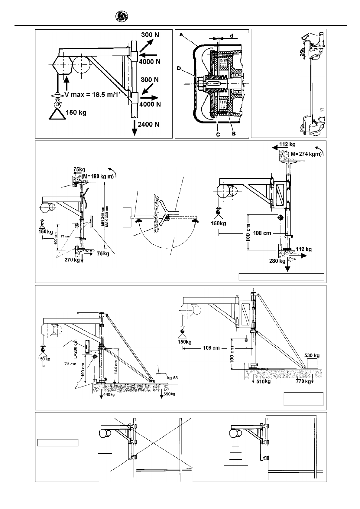
2. SUPPORTI PER L ELEVATORE
La struttura su cui l elevatore viene applicato deve essere in
grado di sopportare le sollecitazioni indicate in fig. 4, che si
generano durante il funzionamento.
IMER dispone di una ampia scelta di supporti, rappresentati in
figura 6 -7- 8 -10 -11 e 12, previsti per le diverse applicazioni di
cantiere, progettati in modo da trasmettere idoneamente alle strut-
ture questi carichi.
Le forze, indicate agli appoggi di ciascun supporto, dovranno
essere considerate nel calcolo di verifica delle strutture di so-
stegno (ponteggi, terrazze, soffitti, ecc.) effettuato da tecnico
competente.
In caso di applicazione dell' elevatore su ponteggio, que-
sto deve essere opportunamente controventato (vedere
fig. 9)
Per l installazione dei diversi supporti, seguire le istruzioni di cui
ciascuno è fornito.
Nel caso si utilizzino dei supporti con portata diversa
dall elevatore, sull insieme dell apparecchio installato dovrà es-
sere affissa, ben visibile la portata ammissibile in funzione del-
l elemento più critico del sistema.
2.1 PREDISPOSIZIONE DEL POSTO DI LAVORO
- Il lato dell apertura di accesso del carico al piano
deve essere protetto con un parapetto di altezza supe-
riore a 1m ed arresto al piede.
- Accertarsi che la corsa di lavoro sia sgombra per tutta laltezza
e prendere le precauzioni necessarie perchè nessuno possa
sporgersi dai piani intermedi.
- Delimitare l area di carico inferiore perchè nessuno possa so-
starvi durante il sollevamento.
3. MONTAGGIO (fig.1)
1) Il montaggio dell elevatore, così come il suo utilizzo, richiede
personale esperto o che abbia ricevuto le necessarie istruzioni.
Dato il peso dell' elevatore, devono essere impiegati un numero
di operatori tali da non creare situazioni di pericolo durante il suo
trasporto ed installazione.
2) Laltezza massima di lavoro (25m) è quella relativa alla posi-
zione del motoriduttore corrispondente al perno superiore del
supporto.
3) posizionare i morsetti sulla struttura dell edificio, verificare
l allineamento verticale dei perni di sostegno (10) quindi inserire
le boccole del telaio sui perni ed applicare la rondella e la copiglia
di sicurezza antisfilamento (11) del morsetto superiore.
4) Nel caso di montaggio su supporto a cavalletto, fissare il telaio
al cavalletto mediante i fori di fissaggio previsti (fig. 12) utilizzan-
do viti e dadi autobloccanti forniti con il carrello, seguire per il
resto le istruzioni fornite con il
cavalletto.
5) Liberare il gancio.
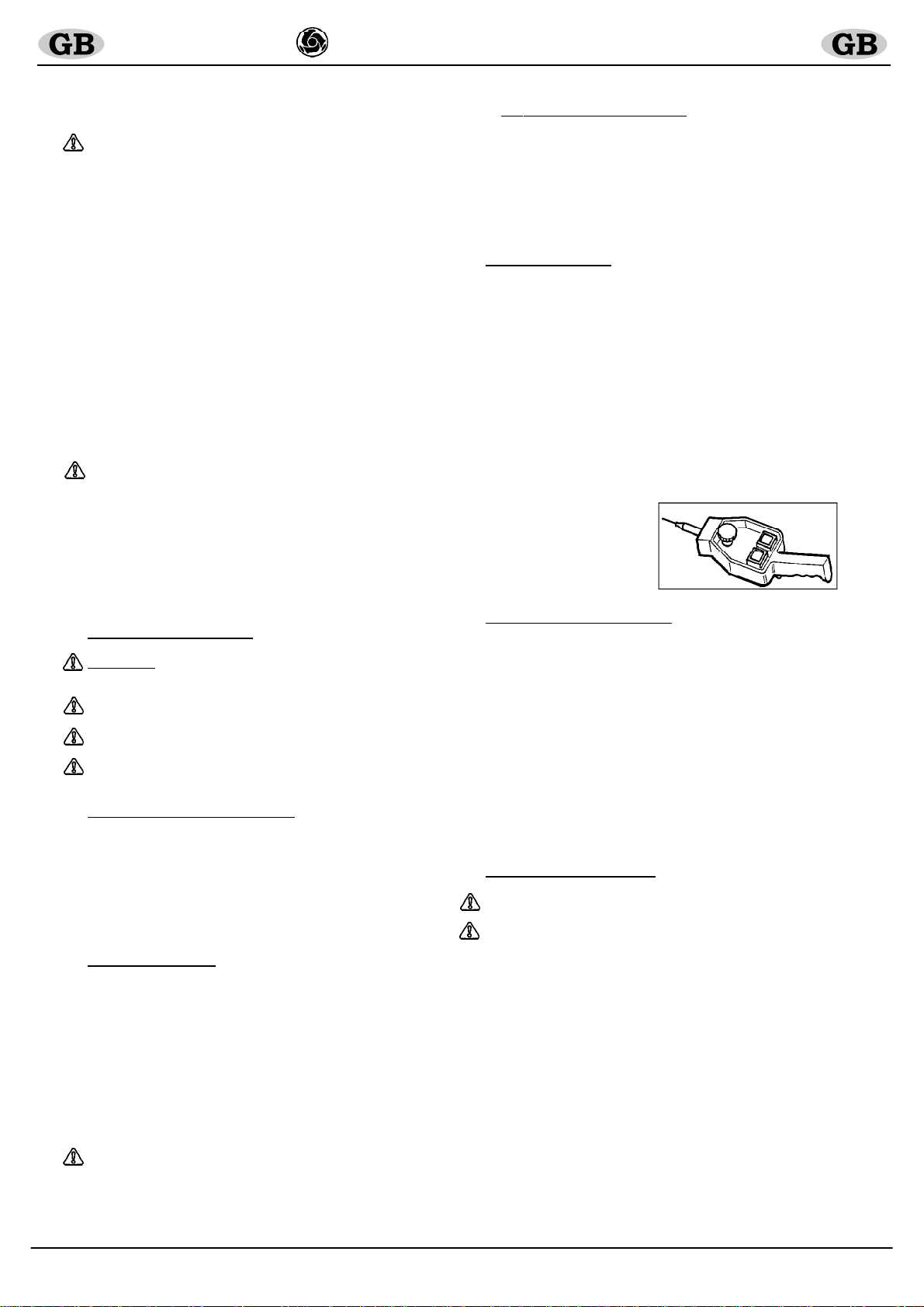
L elevatore è dotato di
pulsantiera a 3 pulsanti (fig.2):
nero = discesa, bianco = salita,
rosso = arresto d emergenza.
4. ALLACCIAMENTO ALLA RETE ELETTRICA
- Verificare che la tensione risulti conforme ai dati di targa della mac-
china.
- Verificare inoltre che la tensione di linea sia compresa tra +/- 5% del
valore nominale.
- La linea elettrica di alimentazione deve essere provvista sia di prote-
zione contro le sovracorrenti, sia di tipo differenziale e che il condut-
tore di collegamento a terra abbia una sezione come quella del condut-
tore. Il dimensionamento dei conduttori deve tener conto delle correnti
di avviamento e della lunghezza della linea per evitare eccessive
cadute di tensione (rif. Tab.1).
Evitare l impiego di prolunghe avvolte a spire sui tamburi.
- Il conduttore di alimentazione deve essere di tipo adatto per frequenti
movimenti e rivestimento resistente alla abrasione (per esempio H07RN-
F).
- Collegare la spina alla macchina avvitando la ghiera di ritegno mecca-
nico e grado di protezione IP67.
- L elevatore è così pronto per la prima manovra di collaudo.
5. ISTRUZIONI DI COLLAUDO
- Attenzione!! Questa prova deve essere fatta da persona-
le esperto e competente e devono essere prese le necessa-
rie precauzioni per la sicurezza del personale.
- Attenzione: il collaudo deve essere eseguito prima dell
utilizzo dell elevatore.
Prima di iniziare il collaudo verificare accuratamente che tutta
l installazione dell elevatore sia stata eseguita correttamente.
Fig.2

- 4 -
IMER INTERNATIONAL S.p.A.
ES 150 (110V/50Hz)
1) far discendere a vuoto la fune, agendo sul pulsante di disce-
sa, fino al piano di carico inferiore, verificando che, a fine corsa,
sul tamburo restino almeno tre spire avvolte.
2) Prova di ciclo a vuoto.
Applicando un piccolo carico (20kg),
verificare il corretto funzionamento della macchina effettuando
una corsa completa di salita e discesa.
Provare i pulsanti di salita, discesa e di emergenza, azionamento
fine corsa superiore e corretto avvolgimento del cavo sul tambu-
ro, azionamento del freno.
3) Prova di carico.
Deve essere eseguita applicando il carico di
portata massima prevista dall elevatore. Effettuare l intera corsa
di salita e discesa per verificare gli ancoraggi dellelevatore e del
dispositivo di frenatura.
Dopo la prova deve essere verificato se nelle strutture sono
presenti eventuali cedimenti o assestamenti, ripetendo il control-
lo dell allineamento orizzontale del tamburo (usando una livella
come in fig.1).
4) L elevatore è provvisto di un dispositivo di sicurezza che
arresta la corsa della macchina nel punto di massima salita, ma è
buona norma evitarne l intervento arrestando il sollevamento ri-
lasciando il relativo pulsante di comando.
Al termine della prova deve essere riportata la data, la verifica
della installazione e la firma sul verbale dei controlli (Tab.2) ed
eventuali osservazioni.
Ogni qualvolta si riprende il lavoro, dopo un periodo di inutilizzo
prolungato, è necessario verificare l elevatore prima di iniziare il
lavoro, eseguendo una prova di ciclo a vuoto (secondo le indica-
zioni riportate nel punto 2).
La procedura di collaudo indicata, completa della pro-
va di ciclo a vuoto
2) e
carico
3), dovrà essere effettuata
ad ogni nuova installazione della macchina.
6. RACCOMANDAZIONI D USO E DI SICUREZZA
1) Non sollevare carichi superiori alla portata dell
elevatore.
2) Assicurarsi che il carico sia ben collegato al gancio
dell' elevatore.
3) Assicurarsi che non fuoriesca parte del carico durante
le fasi di sollevamento.
4) Non avvicinare le mani o parti del corpo sul tamburo
durante il funzionamento, perchè potrebbero rimanere
impigliate nella fune che si avvolge causando gravi in-
fortuni.
5) Non avvicinare le mani o parti del corpo sul contrap-
peso durante la fase di salita, perchè potrebbero subire
uno schiacciamento con la leva di finecorsa.
6) Evitare l uso della macchina in caso di condizioni
ambientali avverse (forte vento o temporali) in quanto il
carico non è guidato.
7) La posizione di comando e le condizioni di illumina-
zione devono consentire la perfetta visibilità del carico
per tutta la corsa di lavoro.
8) Assicurarsi che almeno n° 3 spire rimangano sempre
avvolte sul tamburo per non forzare l attacco della fune.
L operatore che aziona la macchina, deve evitare l inversione
dell avvolgimento della fune sul tamburo, poichè in questo caso
quando il contrappeso urta la leva di finecorsa (rif.8, fig.1) non
interviene il dispositivo di sicurezza che arresta la corsa con
possibilità di danneggiamento dell elevatore. Se ciò dovesse ac-
cadere, verificare l integrità dell elevatore e riavvolgere la fune
correttamente.
- Assicurarsi che tutte le protezioni siano al loro posto.
- Durante l uso controllare che la fune di acciaio si av-
volga in maniera corretta, spira contro spira, senza
allentamenti o accavallamenti, che sono cause di danni
alla fune stessa. Se ciò avvenisse svolgere la fune e
riavvolgere in maniera corretta tenendola in tensione.
- Tenere i bambini a distanza dall argano.
- Quando l elevatore non viene utilizzato, non permette-
te che persone estranee possono usarlo.
- É vietato l impiego dell elevatore per trazioni oblique.
- É vietato ruotare l' elevatore sui supporti tirandolo per
la pulsantiera: deve essere ruotato manualmente dal te-
laio.
7. VERIFICHE E MANUTENZIONI
Attenzione!! Tutti gli interventi di manutenzione devono
essere eseguiti dopo aver fermato la macchina, tolto il
carico e scollegata la presa di alimentazione.
- Le riparazioni devono essere effettuate da personale specia-
lizzato o nei Centri Assistenza IMER.
- Per la sostituzione di parti guaste utilizzare esclusivamente
ricambi originali.
- Controllare ogni 6/7 giorni l efficacia del freno del mo-
tore elettrico.
- Mantenere sempre leggibili le scritte e le segnalazioni
sulla macchina.
- Rimuovere ogni sporcizia che si depositasse sulla mac-
china.
- Mantenere sempre efficiente il funzionamento del
finecorsa di salita.
- Assicurarsi sistematicamente dello stato del cavo elet-
trico ogni qualvolta si inizia l uso della macchina, qual-
cuno inavvertitamente e/o inconsapevolmente potrebbe
averlo danneggiato.
7.1 FUNE D ACCIAIO
Utilizzare esclusivamente funi nuove, con caratteristiche con-
formi a quanto di seguito prescritto, dotate di attestato di confor-
mità ed identificazione.
- Diametro esterno
(mm)
5
- Formazione 133 fili (19x7) antigiro
- Senso avvolgimento crociato dx
- Resistenza filo elementare
(N/mm²)
1960
- Carico minima rottura fune (kN) 16.07
- Lunghezza (m) 26
- Trattamento superficiale ingrassata
- Il codice Rif. IMER è riportato nella tabella ricambi.
7.1.1 SOSTITUZIONE DELLA FUNE
- La sostituzione deve essere effettuata da un manutentore
competente.
Svolgere completamente la fune. Sfilarla dall interno del tamburo
attraverso l apposito foro e dall asola con il morsetto. Per mon-
tare la nuova fune con il gancio, redancia e ferula già pressata,
occorre far passare il contrappeso nell estremità libera e quindi
inserirla nel foro e nell asola del tamburo, serrare il morsetto e
farlo entrare all interno, tirare ed avvolgerla nel senso di lavoro
disponendola correttamente spira contro spira in strati succes-
sivi. Controllare il funzionamento del finecorsa superiore.
7.1.2 CONTROLLI PERIODICI
Verificare visivamente lo stato della fune giornalmente
od ogni qual volta si presentino sollecitazioni anomale
(attorcigliamenti, forti incastri nelle spire, piegature o
sfregamenti).
Sostituire la fune in presenza dei difetti indicati in fig.13.
Trimestralmente esaminare accuratamente l intera fune ed in
particolare i punti terminali registrandone il risultato nella
scheda
nel manuale Tab.2 che deve essere
conservato dal respon-
sabile di cantiere.
Procedere alla sostituzione almeno ogni anno.
7.2 REGOLAZIONE DEL FRENO MOTORE (Fig. 5)
Il freno a disco ad azionamento meccanico, interviene in man-
canza dell alimentazione elettrica al dispositivo magnetico di aper-
tura.
In caso di riduzione della capacità frenante occorre far control-
lare dal manutentore competente l apparecchio che, se neces-
sario provvederà alla sua registrazione.
Attenzione!! Prima di intervenire sul freno assicurarsi
che il carico sia staccato e che la sua spina di alimenta-
zione sia scollegata.

- 5 -
IMER INTERNATIONAL S.p.A.
ES 150 (110V/50Hz)
Togliere il copriventola (A), regolare il traferro (d) tra il magnete
(B) ed il disco freno (C) usando uno spessimetro: il traferro (d)
deve essere 0.4 mm.
La misurazione dovrà essere effettuata su tre punti diversi in
modo da verificare il parallelismo del disco facendo scivolare
leggermente avanti e indietro lo spessimetro.
Se il traferro è troppo grande, ridurlo avvitando il dado (D) con
chiave esagonale. Se il traferro è piccolo, aumentarlo svitando
il dado (D). Misurare più volte la nuova distanza (d).
Quando la distanza è stata regolata conformemente alle dimen-
sioni sopra elencate, riposizionare la copertura (A).
Per controllare la tenuta dei freni, dopo aver effettuato la regi-
strazione, verificare più volte l azione frenante a pieno carico.
7.3 LUBRIFICAZIONE MOTORIDUTTORE
- Non devono esserci perdite di olio dal gruppo motoriduttore: la
presenza di vistose perdite può significare lesioni nella struttu-
ra di alluminio. In questo caso procedere immediatamente all'
ermetizzazione o sostituzione del carter.
- Controllare il livello dell olio del riduttore attraverso
la spia, prima di ogni messa in opera. Rabboccare in
caso di mancanza. Il cambio è previsto dopo circa 2000
ore di lavoro. Usare olio da ingranaggi viscosità ISO
VG 460 a 40° C.
- L olio esausto è rifiuto speciale, pertanto va smaltito
a norma di legge.
7.4 IMPIANTO ELETTRICO
Controllare l integrità della custodia isolante della pulsantiera
provvedendo alla sua sostituzione, in caso di danneggiamento
della tenuta, con ricambio originale IMER.
8. TRASPORTO E MESSA FUORI ESERCIZIO
- Non lasciare incustodito l elevatore installato senza aver tolto
la linea di alimentazione e riavvolta la fune interamente sul
tamburo.
Lasciando inattiva la macchina per lungo tempo è buona norma
tenerla protetta dagli agenti atmosferici.
- Durante il trasporto proteggere dagli urti e dallo schiacciamento
le varie parti della macchina.
9. INCONVENIENTI / CAUSE / RIMEDI
9.1 IN CASO DI GUASTO DELLA MACCHINA CON
INCONVENIENTI
CAUSE
RIMEDI
Premendo i
pulsanti di
azionamento
(salita o discesa)
la macchina non
funziona.
- Il pulsante di
emergenza è
premuto.
- Non arriva
tensione alla
macchina.
- La presa e la
spina elettrica non
sono ben
collegate.
- E' intervenuto
l' interruttore di
protezione del
quadro esterno di
alimentazione.
- Il cavo di
alimentazione
dalla spina al
quadro è
interrotto.
- Un filo elettrico
all' interno del
quadro è
scollegato.
- Se l'
inconveniente
persiste
- Disattivare il
pulsante
ruotandolo.
- Controllare la
linea.
- Ripristinare il
corretto
collegamento.
- Ripristinare il
magnetotermico.
- Cambiare il cavo.
- Collegare di
nuovo.
- Rivolgersi all'
Assistenza IMER
CARICO SOSPESO
- Se possibile, rimuovere il carico accedendo dal livello in cui si
trova, quindi togliere l elevatore e provvedere alla sua manuten-
zione.
- Altrimenti utilizzare un altro apparecchio di sollevamento (di
portata sufficiente) posto più in alto, sospendere l apparecchio
guasto sia nella zona del carico che vicino agli attacchi.
Sollevarlo lentamente in modo da liberarlo dagli attacchi, quindi
calare tutto a terra.
- Non tentare di agire sul dado di regolazione del freno perché
sfuggirebbe.
- Non cercare di riparare il guasto intervenendo sulla macchina
con carico sospeso.
10. LIVELLO DI RUMOROSITA
ALL
ORECCHIO
DELL
OPERAT
ORE
Il livello Lp(A) indicato nella tabella DATI TECNICI corrisponde al
livello equivalente ponderato di pressione sonora in scala A pre-
visto dalla 98/37/CE. Tale livello è misurato a vuoto, alla testa
delloperatore in posizione di lavoro a 1,5 metri dall apparecchio,
considerando le diverse condizioni di lavoro.

- 6 -
IMER INTERNATIONAL S.p.A.
ES 150 (110V/50Hz)
Dear Customer, Congratulations on your choice of purchase:
IMER hoists are the result of years of experience and are
equipped with all the latest technical innovations.
WORKING IN SAFETY: to work in complete safety, read
the following instructions carefully.
This OPERATION AND MAINTENANCE manual must be kept on
site by the person in charge and must always be available for
consultation.
The manual is to be considered integral part of the machine and
must be kept for future reference (EN 292/2) until the machine is
disposed of. If the manual is damaged or lost, a replacement may
be requested from the hoist manufacturer.
The manual contains important information regarding site
preparation, machine use, maintenance procedures, and
requests for spare parts. Nevertheless, the installer and the
operator must both have adequate experience and knowledge
of the machine prior to use.
To guarantee complete safety of the operator, safe operation
and long life of equipment, follow the instructions in this manual
carefully, and observe all safety standards currently in force for
the prevention of accidents at work (use of suitable footwear
and clothing, helmets, safety harnesses, installation of adequate
railings around voids, etc.);
It is strictly forbidden to carry out any form of
modification to the steel structure or working parts of
the machine.
IMER INTERNATIONAL declines all responsibility for non-
compliance with laws and standards governing the use of this
equipment, in particular: improper use, defective power supply,
lack of maintenance, unauthorised modifications, tampering and/
or damage and partial or total failure to observe the instructions
contained in this manual.
1.GENERAL DESCRIPTION
Warning: The hoist must be operated by qualified
personnel only who must be familiar with all relative
instructions and proceed with caution.
1) The hoist is designed for lifting material and for use
on construction sites.
2)
Use of the hoist to lift persons and/or animals is strictly
forbidden.
3)
Never use the hoist in environments subject to the risk
of explosion or fire or in underground sites.
The standard hoist comprises (fig.1):
-
Drum-type winch comprising drum (ref.3) mounted on reduction
gear shaft (ref.12), wire rope (ref.1), lifting hook (ref.2) and
counterweight (ref.9).
-
Reduction unit comprising brake motor (ref.4) and oil-bath
lubricated reduction gear (ref.12).
-
Electrical installation (ref.5) with pendant control unit (ref.7).
-
Limit switch lever (ref.8)
-
Load bearing frame (ref.6)
2. HOIST BRACKETS
The hoist bracket must have adequate tolerance to load stress
generated during operation as indicated in fig.4.
There is a vast range of brackets available, as shown in the
relative figures6, 7, 8, 10, 11, and 12 for various applications on
construction sites and designed to transmit relative loads to the
supporting structure.
The force applied on the bracket clamp points must be taken into
account for load calculations during inspections (scaffolding,
balconies, ceilings etc.). Inspections must be carried out by a
qualified technician.
In the case of hoist application on scaffolding, ensure
that suitable bracing is installed (see fig.9)
For bracket installation, follow the relative instructions supplied.
If bracket capacities differ from that of the hoist, affix a sign
indicating admissible capacity in relation to the most critical element
of the system.
2.1
WORK SITE PREPARATION
The opening side for access to the loading area must be protected
with railings at least 1 m high and a toe guard.
Ensure that the lifting area is unobstructed throughout the entire
height and take necessary precautions to ensure that no person
can lean out of intermediate floors.
Ensure delimitation of the lower loading surface to impede access
during lifting operations.
3. ASSEMBLY (fig.1)
1) Assembly must be carried out exclusively by qualified
personnel who must be supplied with all the relative assembly
instructions.
Given the weight of the hoist, ensure that the number of operators
assigned for assembly is sufficient to ensure complete safety
during transport and installation.
2) Maximum working height (25 m) is measured from the ground
and the reduction unit to the upper clamp of the bracket.
3)
Fit clamps onto the building support and ensure vertical
alignment of pins (10). Insert the bracket bushings onto the pins
and fit the washer and safety cotter pin (11) on the upper clamp.
4)
In the case of hoist gantry assembly, secure the gantry by
means of the pre-drilled holes (fig.12) using the self-locking
screws and nuts supplied with the unit. Follow the relative
instructions supplied with the
gantry.
5)
Release the hook
The hoist is fitted with a 3-
button pendant control (fig.2):
black = descent; white =
ascent, red = emergency stop
4.
ELECTRICAL CONNECTION
-
Check that the voltage corresponds to rating plate indications.
-
Check also that mains voltage is between +/- 5% of the rated
value.
-
Ensure that the electric power cable is fitted with an overload
cutout device, and that the earthing cable is the same size as the
mains cable. Cable dimensions must be commensurate with the
requirements for start-up currents and cable lengths to avoid
excessive voltage drops (see table 1).
-
Do not use extension leads wound onto storage reels.
-
The mains cable must be suited to frequent movement and
feature wear-resistant sheathing (e.g. H07RN-F).
-
Connect the plug (IP67 protection category) to the machine by
tightening the lock ring.
-
Proceed with preliminary testing after the above procedure.
5. TESTING INSTRUCTIONS
- WARNING!! This test must be carried out by qualified
staff and all safety precautions must be observed.
-
WARNING Testing must be carried out before using
the hoist.
Before testing the hoist check that installation has been carried
out correctly.
1) Lower the rope under no-load conditions by pressing the
descent pushbutton, until it reaches the lower loading surface.
Ensure that at the end of travel at least three rope turns remain
wound on the drum.
2)
No-load cycle test
: Apply a small load (20 kg) and check that
the machine functions correctly by performing a complete ascent
and descent cycle. Test the following: ascent and descent control
pushbuttons, emergency pushbutton, ascent limit switch
intervention, correct winding of the rope onto the drum and
braking efficiency.
3) Load test: This test must be carried out by applying the
maximum specified load on the hoist. Carry out a complete ascent-
descent cycle and check hoist anchoring and braking system
efficiency. After testing, ensure that there are no signs of yield
or bedding in and repeat the horizontal alignment check on the
drum (use spirit level as shown in figure 1).
Fig.2

- 7 -
IMER INTERNATIONAL S.p.A.
ES 150 (110V/50Hz)
4) The hoist is fitted with a safety device that stops the motor at
the ascent limit position. However, it is preferable to avoid the
activation of the limit switch and simply release the relative
pushbutton to stop ascent.
On completion of testing, compile the test report with the date,
installation check data and signature as well as any relevant
comments (Table 2).
When operation is resumed after prolonged periods of disuse
the entire machine must be tested under no-load conditions
(according to instructions in point 2) before starting.
In the case of new installation, repeat all test operations
(2 - no-load, and 3 - load) listed above.
6. RECOMMENDATIONS AND SAFETY PRECAUTIONS
1) Never lift loads exceeding specified hoist capacity.
2) Ensure that the load is securely attached to the lifting
hook.
3) Ensure that no parts fall from the load during lifting
operations.
4) Keep hands and other parts of the body well clear of
the drum during operation to avoid the risk of entrapment
with rope and consequent physical injury.
5) Keep hands and other parts of the body well clear of
the counterweight to avoid entrapment between the
counterweight and limit switch lever.
6) Avoid use of the hoist in adverse weather conditions
(strong winds or storms) as the load is not guided in this
system.
7) The control position and lighting conditions must
ensure perfect visibility of the load throughout the lif-
ting phase.
8) Ensure that at least three turns of rope remain wound
on the drum to avoid excessive pull on the rope attachment
point.
Avoid reverse winding on the drum; rope descent provokes
failure of limit switch activation on contact with the counterweight
(ref.8, fig.1) which can damage the hoist. If this occurs, check
the hoist for damage and rewind the cable correctly.
- Ensure that all protective devices are correctly fitted.
- During operation, check that wire rope winds onto the
drum correctly, one winding on another, without slack
turns or overlapping which can damage the rope. If this
occurs, unwind the rope and rewind correctly taking care
to maintain sufficient tension.
-
Keep children away from the hoist.
-
Ensure that no unauthorised personnel have access to
the hoist
- Lifting operations that are not carried out in
correspondence to the load s centre of gravity and the
rope pull line are strictly forbidden.
-
Never pull the pendant control cable to rotate the hoist
on the bracket. Rotation must only be carried out
manually from the frame.
7.
CHECKS AND MAINTENANCE
WARNING: Always remove the load from the hoist and
disconnect from the power supply before carrying out
maintenance operations.
- Repairs must be carried out exclusively by qualified personnel
or in IMER service centres.
-
Use only original spare parts.
-
Ensure braking efficiency every 6-7 days.
- Ensure that all signs and symbols on the machine remain
legible
- Clean the hoist regularly.
- Check limit switch efficiency regularly.
- Before using the machine, check the mains cable for
any possible damage which could constitute a hazard to
operation and the hoist.
7.1 WIRE ROPE
Only use new wire ropes which comply with the following
specifications and are accompanied by a declaration of conformity
and identification documentation.
O.D.
5 mm
Construction
133 strands (19x7) kink-proof
Strand twist r.h. cross
Strand resistance
1960 N/mm²
Min. rope breaking load
16.07 kN
Length
26m
Surface treatment Greased
The IMER reference code is indicated in the spare parts list.
7.1.1.
WIRE ROPE REPLACEMENT
Replacement must be carried out by qualified personnel.
Unwind the rope completely.
Pull the rope with clamp out of the hole and slot on the drum. To
fit the new rope with hook, thimble and pressed sleeve, pass the
free end of the rope through the counterweight and insert it into
the hole and then out of slot on the drum; tighten the clamp and
push the rope end back inside the drum by means of the slot. Pull
the rope and wind onto the drum in the correct direction, wind on
wind in consecutive layers. Ensure ascent limit switch efficiency.
7.1.2.
PERIODIC CHECKS
Inspect the condition of the rope daily or in the event of
faulty operation (twisting, bending, kinks or abrasion)
Replace the rope in the event of defects as indicated in fig.13.
Carry out rope checks quarterly; check in particular the rope
ends and note conditions in the relative
table
in the manual
(table 2) which must be kept by the site foreman.
Replace the rope at least once a year.
7.2 MOTOR BRAKE ADJUSTMENT
The hoist is fitted with a mechanical disk brake which is engaged
in the event of failure of power supply to the electromagnetic
release device.
If braking efficiency is reduced, contact a qualified technician to
carry out maintenance.
Warning: Always remove the load from the hoist and
disconnect power supply before carrying out hoist
maintenance.
Remove fan cover (A) and adjust air gap (d) between magnet
(B) and brake disk (C) by means of a feeler gauge: the air gap
must be 0.4 mm.
Measure the air gap at three different points; slide the feeler
gauge backwards and forwards in each point to ensure brake
disk alignment.
If the air gap exceeds the above value, reduce by tightening nut
(D) by means of a hex wrench, slacken if the gap is too small.
Measure the new distance several times (d).
Once adjustment is complete, refit cover (A).
Check braking efficiency by engaging brake several times during
hoist operation under load conditions.
7.3 GEARMOTOR LUBRICATION
Ensure that there are no oil leaks from the gearmotor. Oil leaks
may indicate that the aluminium housing is damaged. In this case,
seal immediately or replace housing.
- Check the gearmotor oil level regularly before
operation by means of the level plug. Top up if necessary.
Oil change is scheduled for every 2000 hours of service.
Use gear oil viscosity ISO VG 460 at 40°C.
-
Contaminated oil is considered special waste and must
be disposed of in accordance with provisions as specified
in the country of installation.
7.4 ELECTRICAL INSTALLATION
Ensure that the pendant control insulation is in perfect condition;
in the event of damage, only use gennine IMER spares.

- 8 -
IMER INTERNATIONAL S.p.A.
ES 150 (110V/50Hz)
PROBLEM
CAUSE
REMEDY
Machine does not
start when
ascent or
descent buttons
are pressed
- Emergency
pushbutton is
pressed
- Faulty power
supply
- Plug not inserted
correctly in socket
- External panel
circuit breaker has
tripped
- Faulty power
cable- Loose wire
in control panel
- If problems
persist
- Rotate
pushbutton to
release
- Check mains line-
Reconnect the
plug
- Reset thermal
magnetic circuit
breaker
- Replace cable
- Reconnect wire
- Contact IMER
Service Centre
8. TRANSPORT AND DECOMMISSIONING
Never leave the installed hoist unattended without first
disconnecting the power supply and rewinding the rope
completely onto the drum.
In the event of prolonged disuse, protect the hoist against
weathering.
During transport, protect machine parts from impact, damage or
crushing.
9. TROUBLESHOOTING
9.1. HOIST BREAKDOWN WITH SUSPENDED LOAD
If possible, remove load via the relative access level and detach
the hoist for maintenance.
If the load cannot be removed, use other lifting equipment (of
sufficient capacity) installed above the hoist and pick up the
hoist by hooking to the part directly above the rope pull line and
also the supporting structure.
Lift the hoist slowly to detach it from the clamps and then lower
to the ground.
Do not attempt to adjust the brake adjustment nut to avoid the
loss of brake control and consequent hazards.;
Never attempt maintenance with the hoist under load conditions.
10. NOISE LEVEL AT THE OPERATOR S EAR
The level Lp(A) given in the TECHNICAL DATA chart corresponds
to the weighted equivalent sound pressure level on scale A of
European Directive 98/37. This level is measured with no load,
at the operator s head in the working position 1.5 metres away
from the instrument, considering the different working conditions.
WARNING!
Additional measures shall be taken to prevent
any person falling or any person being struck
by falling object, according to the relevant
regulations in the country of use.

- 9 -
IMER INTERNATIONAL S.p.A.
ES 150 (110V/50Hz)
SCHEMA ELETTRICO - SHEMA ELECTRIQUE - WIRING DIAGRAM - SCHALTAPLAN - ESQUEMA ELECTRICO
Fig.3
TAB.1
Lunghezza cavo (m) / Longueur câble (m) / Cable length (m) / Kabel Länge (m) / Longitud
cable (m) 0 ÷ 10 11 ÷ 1617 ÷ 25
sezione cavo (mm²) / section câble (mm²) / cable (mm²) / kabel (mm²) / cable (mm²) 3x 1.5 2.5 4
I F GB D E
L1
CONDUTTORE LINEA
CONDUCTEUR DE
LIGNE PHASE
PHASE WIRE
PHASENLEITER
CONDUCTOR DE
LÍNEA FASE
N
CONDUTTORE LINEA
NEUTRO
CONDUCTEUR DE
LIGNE NEUTRE
NEUTRAL WIRE
MITTELLEITER
CONDUCTOR DE
LÍNEA NEUTRO
PE
CONDUTTORE DI
PROTEZIONE
CONDUCTEUR DE
PROTECTION
EARTH WIRE
SCHUTZLEITER
CONDUCTOR DE
LÍNEA PROTECCIÒN
S1
PULSANTE DI
EMERGENZA
BOUTON-POUSSOIR
D' URGENCE
EMERGENCY
BUTTON
NOT-DRUCKSCHALTE
BOTÒN DE
EMERGENCIA
S2
PULSANTE SALITA
BOUTON-POUSSOIR
MONTEE
UP BUTTON
DRUCKSCHALTER
HEBEN
BÒTON DE SUBIDA
S3
PULSANTE DISCESA
BOUTON-POUSSOIR
DESCENTE
DOWN BUTTON
DRUCKSCHALTER
HEBEN
BOTON DE BAJADA
S4
FINECORSA SALITA
FIN DE COURSE
DESCENTE
DOWN SWITCH
ENDSCHALTER HUB
FINAL DE CARRERA
SUBIDA
AS
AVVOLGIMENTO
SALITA MOTORE
ENROULEMENT
MOTEUR MONTEE
MOTOR WINDING, UP MOTORWICKLUNG
HUB
BOBINADO MOTOR
SUBIDA
AD
AVVOLGIMENTO
DISCESA MOTORE ENROULEMENT
MOTEUR DESCENTE
MOTOR WINDING,
DOWN
MOTORWICKLUNG
SENKEN
BOBINADO MOTOR
BAJADA
AM
AVVOLGIMENTO
MAGNETE FRENO
ENROULEMENT
AIMANT FREIN
BRAKE MAGNET
WINDING
WICKLUNG
BREMSMAGNET
BOBINADO
MAGNETO DEL
FRENO
PR
ALIMENTATORE
MAGNETE FRENO
ALIMENTATEUR
AIMANT BRAKE RECTIFIER
SPEISEGERÄT
MAGNET
ALIMENTATOR
MAGNETO
C1
CONDENSATORE
CONDENSEUR
CAPACITOR
KONDENSATOR CONDENSADOR
X1
CONNETTORE
ALIMENTAZIONE
MAGNETE FRENO
CONNECTEUR
ALIMENTATEUR
AIMANT
BRAKE MAGNET
CONNECTOR
VERBINDER
MAGNET-
SPEISEGERÄT
CONECTOR DEL
ALIMENTADOR
MAGNETO
X2
CONNETTORE
MOTORE
CONNECTEUR
MOTEUR
MOTOR CONNECTOR
MOTORVERBINDER
CONECTOR DEL
MOTOR
X3
CONNETTORE
CONDENSATORE
CONNECTEUR
CONDENSATEUR
CAPACITOR
CONNECTOR
KONDENSATOR
VERBINDER
CONECTOR
CONDENSADOR
X4
MORSETTI
CONNESSIONE
MAGNETE
BORNES AIMANT
MAGNET TERMINALS
KLEMMEN MAGNET
BORNES DEL
MAGNETO
(R1)

- 10 -
IMER INTERNATIONAL S.p.A.
ES 150 (110V/50Hz)
Fig.4 Fig.5
PUNTELLO PER INTERNI
POTEAU POUR INTERIEURS
HOIST FRAME FOR INTERMEDIARY FLOORS
GESCHOßSTÜTZE
PUNTAL PARA INTERIORES
PARAPETTO
PARAPET
PARAPET
BRÜSTUNG
PARAPETO
TRAVE
POUTRE
BEAM
TRÄGER
VIGA
POSIZIONE APPOGGIO SUPERIORE
POSITION D'APPUI SUPÈRIEURE
POSITIONING TOP FOOTANORDNUNG DER
OBERE AUFLAGE
POSICION APOYO SUPERIOR
ELEVATORE
APPAREIL DE LAVAGE
HOIST
AUFZUG
ELEVADOR
TRAVE
POUTRE
BEAM
TRÄGER
VIGA
LIVELLA
NIVEAU
SPIRIT LEVEL
WASSERWAAGE
NIVEL
ZONA LAVORO OPERATORE
ZONE DE TRAVAIL OPÉRATEUR
OPERATOR WORK ZONE
ARBEITSBEREICH DES BEDIENERS
ZONA DETRABAJO OPERADOR
Fig.7
KIT PER PUNTELLO DA ESTERNI
KIT POUR POTEAU D' EXTERIEUR
HOIST FRAME FOR ROOFS
BAUSATZ AUßENSTÜTZE
KIT PARA PUNTAL DE EXTERIORES
Fig.8
PARAPETTO
PARAPET
PARAPET
BRÜSTUNG
PARAPETO
CONTENITORE ZAVORRA
CONTENEUR LEST
COUNTER WEIGHT
BALLAST
CONTENEDOR DE CONTRAPESO
CONTENITORE ZAVORRA
CONTENEUR LEST
COUNTER WEIGHT
BALLAST
CONTENEDOR DE CONTRAPESO
LIVELLA
NIVEAU
SPIRIT LEVEL
WASSERWAAGE
NIVEL
Fig.9
ATTACCO A PONTEGGIO
FIXATION SUR ECHAFAUDAGE
HOIST FRAME FOR SCAFFOLDING
GERÜSTBEFESTIGUNG
CONEXIÓN PARA ANDAMIO
NO!
NON!
FALSCH!
SI!
OUI!
YES!
RICHTIG!
Fig.6
- MORSETTI PER PONTEGGIO
- COLLIRS DE FIXATION POUR
ÉCHAFAUDAGE
- SCAFFOLD ATTACHMENT
CLAMPS
- GERÜSTKLAMMERN
- ABRAZADERAS PARA
ANDAMIOS
cod. 1199102 - cod. 1199115
cod. 1199134
cod. 1199131
cod. 1199170

- 11 -
IMER INTERNATIONAL S.p.A.
ES 150 (110V/50Hz)
PROLUNGA
ROLLANGE
JIB EXTENSION
SCHWENKARM
ALARGADOR
Fig.11
FORZE INDICATE AGLI APPOGGI
FORCESINDIQUÉES AUXAPPUIS
FORCES-REFEREDTOSUPPORT
KRÄFTE AN DER AUFLAGE
FUERZA INDICADAS EN LOS APOYOS
ZAVORRA
CONTENEUR
COUNTER
BALLAST
CONTENIDO
Max portata
Débit maxi.
Max capacity
Tragfähigkeit
Capacidad
máx
F1 F2 P
150 kg 590 kg 520 kg 2 x 100 kg
SUPPORTO A CAVALLETTO
CHEVALET
GANTRY HOIST
BRÜCKENSEILZUG
CABALLETTE
Fig.12
P
P
F1
F2
LONGARINA
LONGERON
RUNWAY
FARSCHIENE
LARGUERO
CONTENITORE ZAVORRA
CONTENEUR LEST
COUNTER WEIGHT
BALLAST
CONTENEDOR DE CONTRAPESO
- I valori delle sollecitazioni sugli
appoggi tengono conto di un
coefficiente di sovraccarico statico di
1,25.
- Les forces sur les appuis ont été
calculées avec un coefficient de
surcharge de 1,25.
- The forces on the links are
evaluated considering a overload
coefficient of 1,25.
- Die Belastungswerte auf den
Trägern gehen von einer statischen
Überlastung von 1,25 aus.
- Los valores de las solicitaciones
en los apoyos tienen en cuenta un
coeficiente de sobrecarga estàtica de
1,25.
PUNTELLO A FINESTRA
POTEAU POUR FENETRE
HOIST FRAME FOR WINDOWS
FENSTERKLEMMARM
PUNTAL DE VENTANA
Fig.10
cod. 1199150
CARRELLO PER ELEVATORE
CHARIOT POUR ELEVATEUR
TRAVEL CARRIAGE
FAHRWERK
CARRO PARA ELEVADOR
cod. 1199230
P
P
NO!
NON!
FALSCH!
PP
SI!
OUI!
YES!
RICHTIG!
cod. 1191230
cod. 1199210
cod. 1199105
(R1)

- 12 -
IMER INTERNATIONAL S.p.A.
ES 150 (110V/50Hz)
TAB. 2
VERBALE DI COLLAUDO - PROCES-VERBAL DES CONTROLES - TEST REPORT - PPRÜFUNGSPROTOKOLL - CONDICIONES
Data-Date-Date-Datum-Fecha Funi-Câbles-Ropes-Seile-Cable Macchina-Machine-Machine-Maschine-Maquine
Osservazioni e firma del compilatore
Observations et signature du responsable
Remarks and compiler's signature
Bemerkungen und Unteschrift
Observaciones y firma del encargado

- 13 -
IMER INTERNATIONAL S.p.A.
ES 150 (110V/50Hz)
Fig.13
FORMAZIOME DI ANSE
FORMATION DE BOUCLES
LOOPS
VERSCHLEIß=MATERIALVERLUST UNREGELMÄSSIGE OBERFLÄCHE
FORMACION DE CURVAS
ROTTURA DI SINGOLI FILI
RUPTURE DE FILS
BREAKING OF SINGLE WIRES
FEHLEN EINER LITZE
ROTURA DE HILOS
ROTTURA DI UN TREFOLO
RUPTURE D' UN BRIN
BREAKING OF ONE STRAND
BRECHEN EINZELNER DRÄHTE
ROTURA DE UN RAMAL
CORROSIONE INTERNA O ESTERNA
CORROSION INTERIEURE OU EXTERIEURE
INTERNAL OR EXTERNAL CORROSION
ABFLACHUNGEN ODER AUFWÖLBUNGEN
CORROSION INTERNA O EXTERNA
PUNTI DI VISIBILE APPIATTIMENTO
POINTS D' APLATISSAGE VISIBLE
VISIBLE FLATTENED POINTS
SCHLAUFENDIBILDUNG
PUNTOS DE ACHATAMIENTO EVIDENTE
RICAMBI:
Per tutti gli ordini dei pezzi di ricambio vogliate indicare: 1 - Tipo di macchina. 2 - Numero di codice e di riferimento
collocato in corrispondenza di ogni definizione. 3 - Numero di serie e anno di costruzione riportato sulla targhetta della macchina. SIMBOLOGIA:
Intercambiabilità (esempio): Fino alla macchina matricola N° 5240 è stato installato il rif.1 cod.3204530,dalla mcchina matricola N° 5241 è stato
installato il rif.1.1 cod.3204520. Il rif.1.1 è intercambiabile ( ) con il rif.1. Non sono intercambiabili i rif.1 e rif.1.1 se in tabella è presente il
simbolo ( ).
PIECES DE RECHANGE:
Pour toutes les commandes de pièces de rechange, veuillez indiquer: 1 - Le Type de machine 2 - Le
Numéro de code et de référence se trouvant en face de chaque définition 3 - Le Numéro de série et l'année de construction se trouvant sur la
plaquette d'identification de la machine
SYMBOLOGIE: Intercambiabilità (exemple):Jusqu'à la machine matricule N° 5240, nous avons installé la réf. 1 code 3204530; à partir de la
machine matricule N° 5241, nous avons installé la réf. 1.1 code 3204520. La réf. 1.1 est interchangeable ( ) avec la réf.1. Les réf. 1 et réf. 1.1
ne sont pas interchangebles si le symbole ( ) n'est pas sur le tableau.
SPARE PARTS:
All orders for spare parts must indicate the following: 1 - Type of machine.2 - Part number and position number of
each part.3 - Serial number and year of manufacture reported on the machine's identification plate.
SYMBOL: Interchangeability (example):Pos..1 P.n. 3204530 was installed on machincs up to N° 5240 and Pos.1.1 P.n. 3204520 installed on
machine N° 5241 onwards. Pos. 1.1 is interchangeable ( ) with Pos. 1.Pos. 1 and Pos. 1.1 are not interchangeable if the ( ) symbol
appears in the table.
ERSATZTEILE:
Für Ersatzteilbestellungen bitte die folgenden Angaben machen: 1) Maschinentyp 2) Jeweils zugeordnete Art.-Nr.
und Positionsnummer 3) Seriennummer und Baujahr (Angabe auf dem Maschinenschild)
SYMBOLE: Austauschbarkeit (Beispiel):Bis zur Maschinenummer 5240 ist Ref. 1 Cod. 3204530 und ab Maschinennummer 5241 ist Ref. 1.1
Cod. 3204520 installiert worden. Ref. 1.1 und Ref. 1 sind austaschbar ( ). Ref. 1 und Ref.1.1 sind nicht austauschbar, wenn das Symbol ( )
angegeben ist.
PIEZAS DE RECAMBIO:
Para pedir una pieza de recambio hay que indicar siempre: 1 -El tipo de máquina. 2 -Los números de
gódigo y de referencia indicados en correspondencia de cada definición. 3 -El número de serie y el año de construcción indicados en la placa de
la máquina.
SIMBOLOGIA : Intercambiabilidad (ejemplo): Hasta el equipo con matrìcula N° 5240, se ha instalado la pieza con ref. 1 y còd. 3204530; a partir
de la màquina con matrìcula N° 5241, se ha instalado la pieza con ref. 1.1 y còd. 3204520. La pieza con ref. 1.1 se puede intercambiar ( ) con
la pieza con ref. 1. Si en tabla se halla presente el sìmbolo ( ), las piezas co referencia 1 y 1.1 no son intercabiables.
Rif.
Cod.
I F GB D E
Note
1 3204530
Riduttore Réducteur Reducer Untersetzungsgetriebe Reductor 5240
2 3204520
Riduttore Réducteur Reducer Untersetzungsgetriebe Reductor 5241

- 14 -
IMER INTERNATIONAL S.p.A.
ES 150 (110V/50Hz)
AS015 - 1140906 TAV. 1 ELEVATORE - ELEVATEUR - HOIST - WINDE - ELEVADOR / ES 150
Rif.
Cod.
I F
GB
D E Note
1
2248308
TELAIO CHÂSSIS
FRAME
GESTELL
BASTIDOR
2
2201723
ALBERO TAMBURO ARBRE TAMBOUR DRUM SHAFT
TROMMELWELLE
EJE DE TAMBOR
3
2204550
CUSCINETTO PALIER BEARING
LAGER
COJINETE
6205
4
2203155
SUPPORTO TAMBURO SUPPORT TAMBOUR DRUM SUPPORT
TROMMELLAGER
SOPORTE DE TAMBOR
5
3203826
TAMBURO
TAMBOUR
DRUM
TROMMEL
TAMBOR
6
2260002
LEVA FINECORSA
SALITA LEVIER DE FIN DE
COURSE
LIMIT LEVER
HEBEL
PALANCA FINAL DE
CARRERA
7
2214510
CONTRAPPESO
CONTREPOIDS CABLE WEIGHT GEGENGEWICHT
CONTRAPESO
7.1
2214242
CONTRAPPESO
CONTREPOIDS
BALLAST
GEGENGEWICHT
CONTRAPESO
matr. 36625 - .......
8
2212325
FUNE ACCIAIO CÂBLE EN ACIER STEEL ROPE STAHLSEIL CABLE DE ACERO
10
3203863
TARGA ADESIVA PLAQUETTE ADHÉSIVE ADHESIVE LABEL
AUFKLEBER
PLACA ADHESIVA
11
2213267
GANCIO
CROCHET
HOOK
ZUGHAKEN
GANCHO
12
2229400
LINGUETTA
LANGUETTE
KEY
FEDER
LENGÜETA
6604 8X7X30
13
2207355
ANELLO PARAOLIO BAGUE D'ÉTANCHÉITÉ OIL SEAL RING ÖLABDICHTUNG ANILLO DE RETÉN
52x25x7
15
2237299
DISTANZIALE ENTRETOISE
SPACER
DISTANZRING
SEPARADOR
16
2202499
INGRANAGGIO
ENGRENAGE
GEAR
ZAHNRAD
ENGRANAJE
Z.76 M2
17
2227280
ANELLO ARRESTO BAGUE D'ARR T STOP RING ARRETIERRING ANILLO DE PARADA 7435 E/25
18
2229450
LINGUETTA
LANGUETTE
KEY
FEDER
LENGÜETA
8x7x20
19
2235420
LIVELLO OLIO NIVEAU HUILE OIL LEVEL PLUG
SCHAUGLAS
NIVEL ACEITE
20
2202567
INGRANAGGIO
ENGRENAGE
GEAR
ZAHNRAD
ENGRANAJE
Z.76 M1.75
21
2202497
INGRANAGGIO
ENGRENAGE
GEAR
ZAHNRAD
ENGRANAJE
Z.26 M2
22
2201130
ALBERO PIGNONE ARBRE PIGNON PINION SHAFT RITZELWELLE EJE DEL PIÑÓN
23
2229327
LINGUETTA
LANGUETTE
KEY
FEDER
LENGÜETA
6x6x40
24
2204440
CUSCINETTO PALIER BEARING
LAGER
COJINETE
6004
25
2236555
FLANGIA RIDUTTORE BRIDE RÉDUCTEUR REDUCTION GEAR
FLANGE
FLANSCH
BRIDA DEL REDUCTOR
26
2215165
CARCASSA RIDUTTORE CARCASSE RÉDUCTEUR REDUCTION GEAR
CASING GETRIEBEGEHÄUSE CARCASA DEL
REDUCTOR
27
3213005
TARGA MOTORE
PLAQUETTE
RATING PLATE SCHILDERKIT CHAPA DE MATRÍCULA
28
2204391
CUSCINETTO PALIER BEARING
LAGER
COJINETE 6205 2z
29
3203817
ROTORE
ROTOR ROTOR
LÄUFER
ROTOR
30
3213089
MOTORE
MOTEUR
MOTOR
KOMPLETTER MOTOR
MOTOR
KW 0,7 V110-50
31
2228820
SPINOTTO FICHE GUDGEON PIN STIFT
PASADOR
Ø6X14
32
2222509
VITE VIS
SCREW
SCHRAUBE
TORNILLO 5931 M8x20
33
2222513
VITE VIS
SCREW
SCHRAUBE
TORNILLO 5931 M8x30
34
2222514
VITE VIS
SCREW
SCHRAUBE
TORNILLO 5931 M8x40
35
2222099
VITE VIS
SCREW
SCHRAUBE
TORNILLO 5737 M10x40
37
2224355
ROSETTA ELASTICA RONDELLE ÉLASTIQUE SPRING WASHER UNTERLEGSCHEIBE ARANDELA ELÁSTICA 6798A Ø10
38
2237662
MANICOTTO
MANCHON
SLEEVE
MUFFE
MANGUITO
39
2223650
DADO
ECROU
NUT
MUTTER
TUERCA
5588 M10
40
2238399
REDANCIA
COSSE
THIMBLE SEILKAUSCHE
GUARDACABO
41
2234398
CATENA
CHAÎNE CHAIN
KETTE
CADENA
42
3203866
FUNE ACCIAIO + GANCIO CÂBLE ACIER +
CROCHET
WIRE ROPE + HOOH STAHLSEIL + HAKEN CABLE DE ACERO +
GANCHO
43
2222462
VITE VIS
SCREW
SCHRAUBE
TORNILLO
M4x20
44
2288791
RIVETTO RIVET RIVET ALIUNET
REMACHE
45
3213006
TARGA ELEVATORE
PLAQUETTE
RATING PLATE SCHILDERKIT CHAPA DE MATRÍCULA
46
3213015
PULSANTIERA PUPITRE CONTROL BOARD
STEUERSCHALTER
BOTONERA
47
3203739
SPINA A PARETE FICHE D'ÉTANCHÉITÉ WALL SOCKET
STECKER
ENCHUFE DE PARED V110 IP67
48
3213013
CONDENSATORE
CONDENSATEUR
CAPACITOR
KONDENSATOR
CONDENSADOR
49
3203922
CASSETTA ELETTRICA BOÎTIER ÉLECTRIQUE JUNCTION BOX
GEHÄUSE
CAJA ELÉCTRICA
50
2231420
MOLLA
RESSORT
SPRING
FEDER
MUELLE
51
3200005
MICROINTERRUTTORE FIN DE COURSE
MONTEE
UPSTROKE LIMIT
SWITCH ENDSCHALTER SENKEN FINAL DE CARRERA
SUBIDA
53
2223923
DADO AUTOBLOCCANTE ECROU DE SÛRETÉ SELF LOCKING NUT SELBSTSICHERNDE
MUTTER
TUERCA
AUTOBLOQUEANTE
M.8
54
3203831
RADDRIZZATORE FRENO ELECTRO-AIMANT FREIN BRAKE RECTIFIER BREMSENSPEISEGERÄT RECTIFICADOR FRENO
54.1
3213053
RADDRIZZATORE FRENO ELECTRO-AIMANT FREIN BRAKE RECTIFIER
BREMSENSPESEGERÄT
RECTIFICADOR FRENO matr. 34286 - .......
55
2287131
ELETTROMAGNETE
FRENO
ELECTRO-AIMANT FREIN
BRAKE
ELECTROMAGNET
BREMSMAGNET
ELECTROMAGNETO
FRENO
56
2287136
DISCO FRENO DISQUE FREIN BRAKE DISK BREMSSCHEIBE DISCO FRENO
57
2291458
VENTOLA MOTORE VENTILATEUR MOTEUR MOTOR FAN
LÜFTER
VENTILADOR DEL
MOTOR
58
2291246
COPRIVENTOLA CACHE-VENTILATEUR FAN COVER LÜFTERVERKLEIDUNG CUBIERTA DE
VENTILADOR
59
2223922
DADO
ECROU
NUT
MUTTER
TUERCA
Autobl.MB12
62
2275092
COPERCHIO SCATOLA
ELETTRICA COUVERCLE BOÎTIER
ÉLECTRIQUE CONTROL BOX COVER
KASTENDECKEL
CUBIERTA DE CAJA
ELÉCTRICA
63
2287124
MOLLA
RESSORT
SPRING
FEDER
MUELLE
65
2204452
CUSCINETTO PALIER BEARING
LAGER
COJINETE 6005 2Z
66
2231215
ANELLO ELASTICO BAGUE ÉLASTIQUE SPLIT RING AUSGLEICHRING ANILLO ELÀSTICO 40x20.4x2
67
2237340
ANELLO ELASTICO BAGUE ÉLASTIQUE SPLIT RING AUSGLEICHRING ANILLO ELÀSTICO
68
2290870
CARCASSA E STATORE CARCASSE DU STATOR CASING AND STATOR
STÄNDER
CARCASA Y ESTATOR
69
2291480
COPERCHIO MOTORE COUVERCLE MOTEUR MOTOR COVER
MOTORDECKEL
CUBIERTA DE MOTOR
70
2216327
GUARNIZIONE JOINT
GASKET
DICHTUNG
JUNTA
71
2216331
GUARNIZIONE JOINT
GASKET
DICHTUNG
JUNTA
72
2227700
ANELLO ARRESTO BAGUE D'ARR T STOP RING ARRETIERRING ANILLO DE PARADA 7437 I/52
73
2287121
FRENO A DISCO FREIN À DISQUE DISK BRAKE SCHEIBENBREMSE FRENO DE DISCO
74
2235461
TAPPO OLIO BOUCHON HUILE OIL PLUG
ÖLSTOPFEN
TAPON ACEITE
75
3203565
GUARNIZIONE JOINT
GASKET
DICHTUNG
JUNTA
76
2237301
DISTANZIALE ENTRETOISE
SPACER
DISTANZRING
SEPARADOR
77
2222970
VITE VIS
SCREW
SCHRAUBE
TORNILLO
M5x160
78
2224206
ROSETTA
RONDELLE
WASHER
UNTERLEGSCHEIBE
ARANDELA
6592 12x36x4
79
2229310
LINGUETTA
LANGUETTE
KEY
FEDER
LENGÜETA
6x6x30
80
2222505
VITE VIS
SCREW
SCHRAUBE
TORNILLO 5931 M5x30

- 15 -
IMER INTERNATIONAL S.p.A.
ES 150 (110V/50Hz)
matr. 36625 - ......
matr. 0 - 36624
AS015 - 1140906 TAV. 1 ELEVATORE - ELEVATEUR - HOIST - WINDE - ELEVADOR / ES 150
Rif.
Cod.
I F
GB
D E Note
81
2222018
VITE VIS
SCREW
SCHRAUBE
TORNILLO 5737 M8x35
82
2224140
ROSETTA
RONDELLE
WASHER
UNTERLEGSCHEIBE
ARANDELA
Ø 8x18
83
2224350
ROSETTA ELASTICA RONDELLE ÉLASTIQUE SPRING WASHER UNTERLEGSCHEIBE ARANDELA ELÁSTICA 6798A Ø 8
84
2223570
DADO
ECROU
NUT
MUTTER
TUERCA
5588 M8
85
2223920
DADO AUTOBLOCCANTE ECROU DE SÛRETÉ SELF LOCKING NUT SELBSTSICHERNDE
MUTTER
TUERCA
AUTOBLOCANTE
7474 M10
86
2224340
ROSETTA
RONDELLE
WASHER
UNTERLEGSCHEIBE
ARANDELA
6592 Ø10x20
88
2222470
VITE VIS
SCREW
SCHRAUBE
TORNILLO
M10x35
matr. 36625 - .....
89
2238680
CUNEO PER CAVO CONE POUR CABLE WEDGE FOR STEEL
CABLE
KEGEL FÜR STAHLSEIL CUÑA PARA CABLE matr. 36625 - .....
90
2239400
MORSETTO
BORNE
CLAMP
KLEMME
BORNE
matr. 36625 - .....
91
2206002
BOZZELLO A CUNEO POULIE À CÔNE WEDGE BLOCK SEILBLOCK GARRUCHA EN FORMA
DE CUÑA matr. 36625 - .....
Other manuals for ES 150
1
Table of contents
Languages:
Other IMER Chain Hoist manuals
Popular Chain Hoist manuals by other brands

Starke
Starke ST-01225 instruction manual

Tractel
Tractel Minifor TR 10 Operation and maintenance manual

Sealey
Sealey PH250.V4 instructions

J. D. NEUHAUS
J. D. NEUHAUS PROFI 3 Ti Customer's operating and assembly instructions

Garage Smart
Garage Smart myLIFTER user manual

GÜDE
GÜDE GEKZ 300 Original instructions

J. D. NEUHAUS
J. D. NEUHAUS PROFI 16 Ti Operating and assembly instruction

Ingersoll-Rand
Ingersoll-Rand LC2A015S Product information

Tiger
Tiger TR7 Instruction guide

POWERTEX
POWERTEX PLH-S2 Series user manual

Columbus McKinnon
Columbus McKinnon TIGRIP TBSplus Translated Operating Instructions

Yale
Yale PT operating instructions