6. Keep the work area clean to prevent dirt and other foreign matter from getting
into bearings and other moving parts.
7. All seals and ‘O’ rings should be discarded once they have been removed. New
seals and ‘O’ rings should be used when assembling the hoist.
8. When grasping a part in a vise, always use leather or copper covered vise jaws
to protect the surface of part and help prevent distortion. This is particularly true
of machined surfaces, threaded members and housings.
9. Do not remove any part which is press fit in or on a subassembly unless the
removal of that part is necessary for repairs or replacement.
10. To avoid damaging bearings during hoist assembly or disassembly always tap
or press on bearing inner race for shaft fit bearings or outer race for bore fit
bearings.
CAUTION
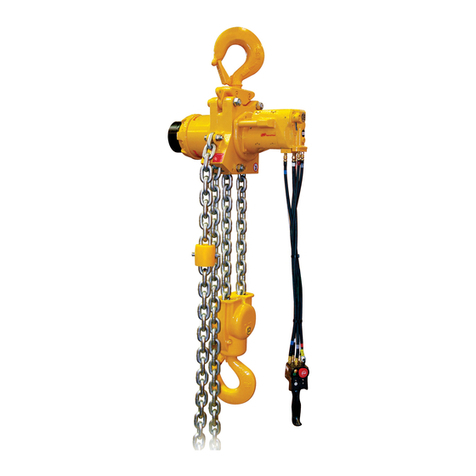
•Useextremecarewhenperforminganymaintenanceonhoist.Hoistweight
may exceed 7,400 lbs (3357 kg) use appropriately rated equipment for
moving.
nPowerhead Disassembly
Refer to Dwg. MHP2343.
1. Remove chain from hoist, by removing retainer ring (171) and chain anchor pin
(170) from lead stripper (159).
2. Disconnect all hoses from hoist motor. Drain oil from reducer, brake and motor
assemblies.
3. Place powerhead assembly in horizontal position and support on blocks.
4. Remove capscrews (703) and lockwashers (702) from motor assembly.
5. Remove motor assembly using the proper equipment necessary to support
weight of the component.
6. If motor repair or general maintenance is required refer to ‘Motor Disassembly’
section on page 28.
7. Remove limit arm (301) as an assembly by removing capscrew (303) that secures
it to motor end frame (152). It is not necessary to remove valves (312) or spacers
(304) unless damaged.
8. Using side holes in frames (154) and (153), rotate powerhead assembly vertically
with motor end frame (152) down. Place blocks along either side of motor end
frame (152) to protect brake shaft (102) from damage.
9. Remove capscrews (202) and lockwashers (702) that secure reduction gear
assembly (200).
10. Using the proper equipment necessary to support weight of component,
remove reduction gear assembly from reduction gear frame end (154) taking
care not to damage or distort the drive shaft (151).
11. It is not recommended to disassemble reduction gear.
12. Remove drive shaft (151) taking care not to damage teeth or distort shape.
13. It is not recommended to remove bushing (169) from drive shaft (151).
14. Remove capscrews (161) and (162) from reduction gear end frame (154) and pry
from center frame (153).
15. Remove capscrews (166) and wear pads (158) from reduction gear end frame
(154) and center frame (153). Check wear pads (158) for damage or wear. Refer
to “INSPECTION” in Product Maintenance Information Manual.
16. Remove drive sheave (155) and lead stripper (159) at the same time. Carefully
pry from center frame (153) both drive sheave and lead stripper. It may be
necessary to use a rubber mallet to loosen lead stripper from dowel pins (168).
Dowel pins (168) do not need to be removed.
17. Remove ‘O’ rings (163) and (164) and bearings (157) from drive sheave (155).
Discard ‘O’ rings.
18. Using side holes on frames (152) and (153), rotate motor end frame (152) so that
motor end frame side is up, this will make disassembly of brake easier.
NOTICE
• Brake assembly is spring loaded, use care when removing motor adapter
(53).
19. Remove capscrews (109) from brake housing (110), and carefully remove motor
adapter (53), springs are located between reaction ring (101) and piston (104).
20. Remove reaction ring (101) and piston (104).
21. Remove ‘O’ ring (116) and discard.
22. Remove from piston (104), seals (113) and (114), check for damage or wear.
23. Remove brake shaft (102) as an assembly, then remove drive discs (111) and
friction discs (112), check for wear.
24. Remove retainer ring (108) and thrust washer (107) from brake shaft assembly.
25. It is not recommended to remove from brake shaft (102) the hub (103), sprag
clutch (105) or bushings (106), unless damage or wear is visible.
26. Remove brake housing (110) and ‘O’ ring (123) from motor end frame (152).
Discard ‘O’ ring.
27. Remove capscrews (161) from motor end frame (152) and pry center frame (153)
from motor end frame. It is not necessary to remove dowel pins (165).
28. Remove idler sheave assembly (156) from motor end frame (152).
29. Remove ‘O’ rings (163) and (164) and bearings (157) from idler sheave (156).
Discard ‘O’ rings.
nTop Hook Disassembly
Refer to Dwg. MHP2345.
1. Remove hoist from mounting structure.
2. To remove hook and plate assembly (hook cannot be removed before hook
plate) remove capscrews (403) and separate hook plate assembly from power
head.
3. To remove hook (352) from hook plate (400) drive out roll pins (355) and remove
nut (353) from threaded hook end.
4. Remove hook (352) and bearing (354) from hook plate (400).
CAUTION
• Do not use swivel ring hook (401) for lifting load, use for installation only.
nBottom Block Disassembly
HA3-100 Hoist
Refer to Dwg. MHP2344.
1. Always make sure load chain is removed before disassembly.
2. Remove capscrews (356) securing hook blocks (351) to hook center block (350)
and pry hook blocks (351) from both sides of hook center block (350).
(Engagement of dowel pins (165) may make removal difficult).
3. Drive out pins (355) from nut (353) in threaded hook section. Pull hook (352)
from hook center block (350) and remove bearing (354) and nut (353).
4. Remove bearings (157), sheaves (156) and ‘O’ Rings (163) and (164) from hook
blocks (351) and hook center block (350). Discard ‘O’ Rings (163) and (164).
nHoist Motor Disassembly
Refer to Dwg. MHP2348.
1. Remove five capscrews (109) from exhaust flange (744). Do not remove the two
capscrews (747) from throttle valve assembly (260).
2. Removepilot controlvalve housing(621) bypullingitoutofmotorhousing(720)
as an assembly with exhaust flange (744).
CAUTION
• Do not remove the exhaust flange (744) until rotary valve (740) has been
removed from rotary valve housing (739).
3. Remove rotary valve (740) by pulling it out from assembly through the motor
housing end of rotary valve housing (739).
4. Remove exhaust flange (744) and control valve assembly (621) by removing
capscrews (747) and (749), respectively.
5. Remove each cylinder head (705) by removing four capscrews (704). Remove
head gasket (713).
6. Pull cylinder liner (701) straight out.
7. Positionpiston(708) at topofits stroke. Inthisposition, with cylinderlinerpulled
out in step 6, wrist pin (707) can be removed. Remove one retainer ring (709)
from either side of piston (708). Push wrist pin (707) out by hand from one side.
If wrist pin is too tight it is acceptable to carefully heat piston to 200˚ F (93˚ C) or
less and then push wrist pin out.
NOTICE
•If piston, wrist pin, connecting rod or cylinder liner are to be re-assembled,
number each set. Also add radial alignment marks for each piston and
cylinder liner to motor housing.
8. Remove remaining cylinder liners and pistons as described in steps 6 and 7. To
remove crank assembly, all pistons and cylinder liners must be removed.
9. Crank assembly (727) can now be removed with oil slinger (726) by pulling
straight out from motor housing (720). Use care while guiding connecting rods
(710) through inside of motor housing.
n2 Lever Pendant Disassembly
Refer to Dwg. MHP1977.
1. Remove fittings (265) and lifting eye (250).
2. Unscrew plugs (254). Remove springs (255) and balls (256).
3. Tap out pin (257) and remove levers (263).
4. Remove setscrews (260) from pendant handle (264).
5. Remove valve assemblies (262). Remove ‘O’ rings (253) and (259) and protector
(261) from valve assemblies. Discard ‘O’ rings.
6. Remove plug (270) from pendant handle (264).
7. Remove retainer ring (268) and exhaust washer (267).
n4 Lever Pendant Disassembly
Refer to Dwg. MHP1980.
1. Remove fittings (265) and lifting eye (250).
2. Unscrew plugs (254). Remove springs (255) and balls (256).
3. Remove capscrews (280) and (283) and washers (281) from attachment (left)
(286). Remove attachment (left) taking care not to damage pin (284). Separate
pin (284), lever (257) and ‘O’ rings (282) from attachment (left). Discard ‘O’ rings.
4. Repeat step 3 for attachment (right) (287).
5. Tap out pin (257) and remove levers (263).
6. Remove valve assemblies (262). Remove ‘O’ rings (253) and (259) and protector
(261) from valve assemblies. Discard ‘O’ rings.
7. Remove plug (270) from pendant handle (264).
8. Remove retainer ring (268) and exhaust washer (267).
nCleaning, Inspection and Repair
Use the following procedures to clean, inspect, and repair the components of the
hoist.
nCleaning
Clean all hoist component parts in solvent (except for the friction discs). The use of
a stiff bristle brush will facilitate the removal of accumulated dirt and sediments on
thegears andframes.Ifbushingshavebeenremoveditmay benecessarytocarefully
scrape old Loctite® from the bearing bores. Dry each part using low pressure, filtered
compressed air.
8 Form MHD56243 Edition 4
