IMES EPM-Peak User manual

Operation manual EPM-Peak
Software Release 1.0.8.0 2019-01-29
Page 1 of 19

Operation manual EPM-Peak
Software Release 1.0.8.0 2019-01-29
Page 2 of 19
1
Introduction___________________________________________________________ 3
1.1 General __________________________________________________________________3
2
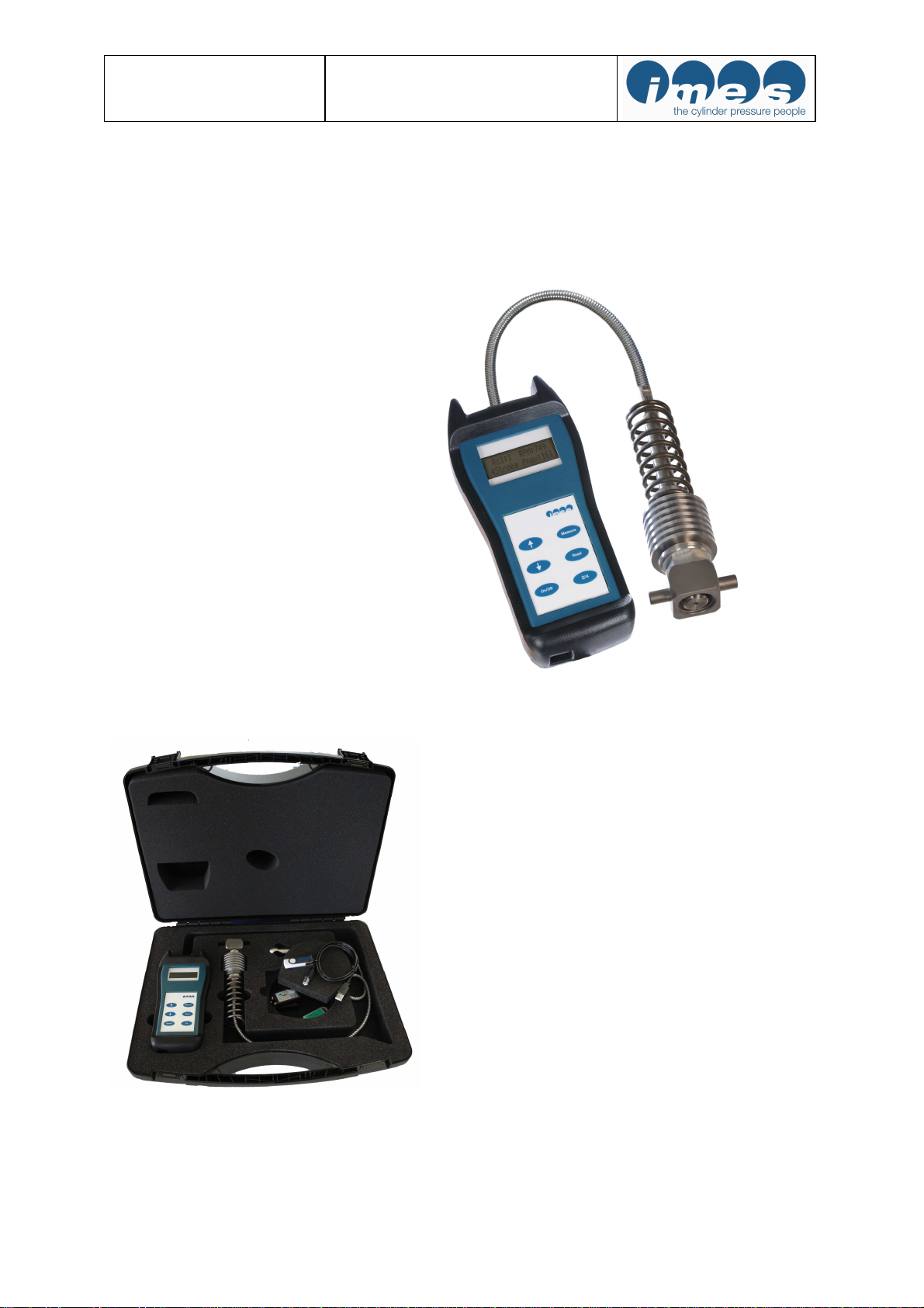
Scope of supply ________________________________________________________ 3
3
Important information __________________________________________________ 4
3.1 Use of the operator manual__________________________________________________4
4
Description ___________________________________________________________ 4
4.1 Introduction ______________________________________________________________4
4.2 Measure functions _________________________________________________________4
4.3 Functional description______________________________________________________5
5
Operation_____________________________________________________________ 5
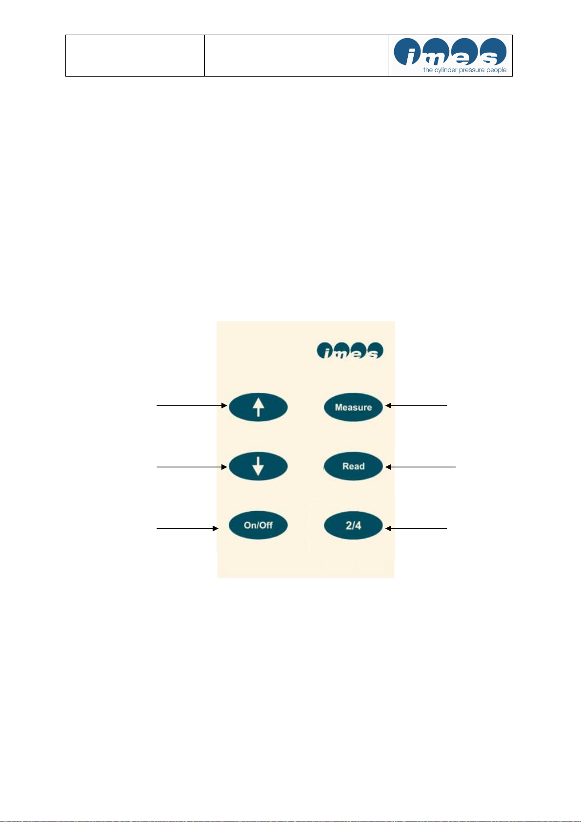
5.1 Operator push buttons _____________________________________________________5
5.2 Operating functions________________________________________________________6
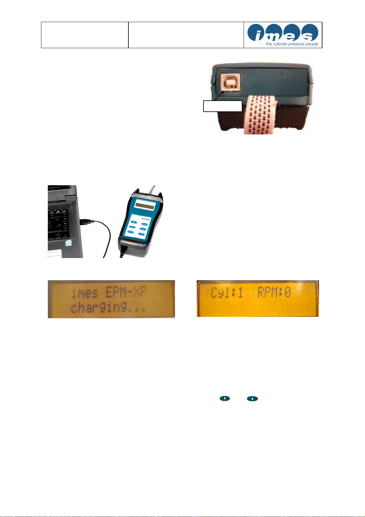
5.3 Charge battery ____________________________________________________________7
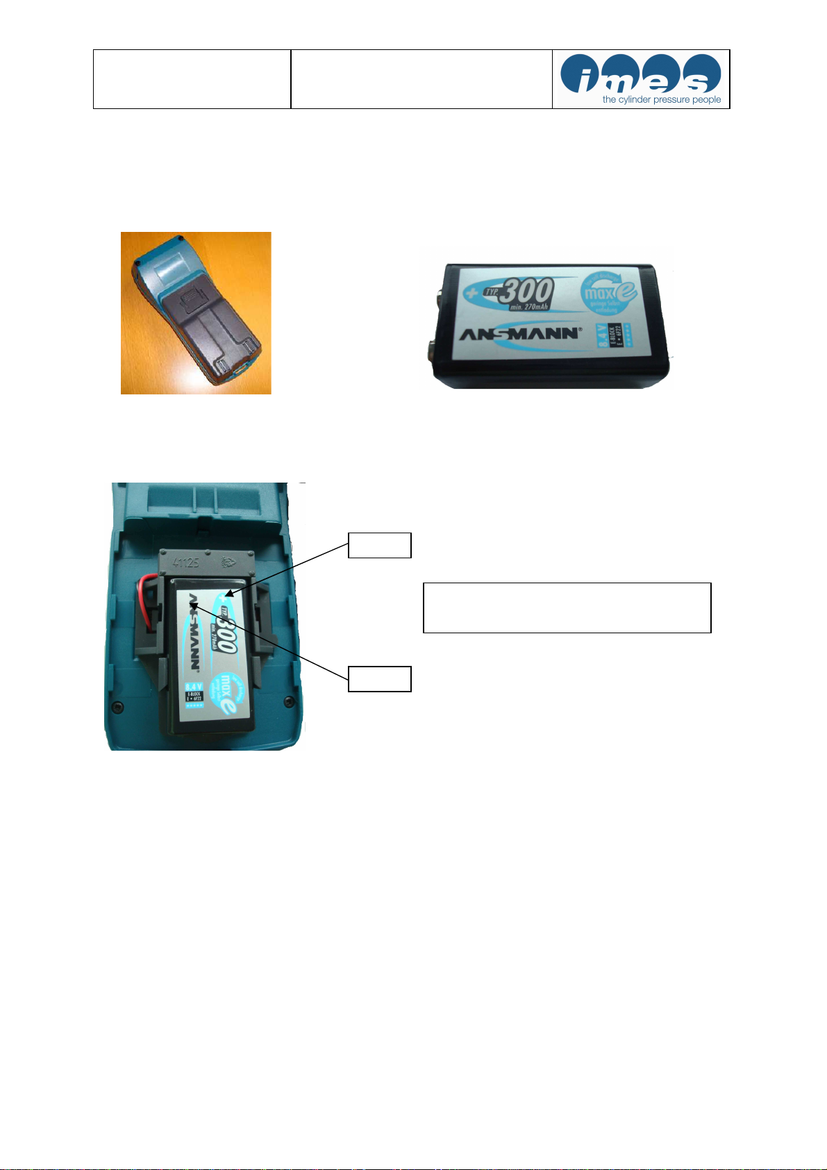
5.4 Change battery____________________________________________________________8
5.5 Mounting instructions on marine engines ______________________________________9
5.6 Measurements with EPM-Peak ______________________________________________9
6
Accuracy check _______________________________________________________ 10
6.1 Connection of EPM-Peak to pressure calibrator _______________________________11
6.2 Generate pressure at pressure calibrator _____________________________________12
6.3 Example of displayed EPM-Peak values during pressure check___________________13
6.4 Disconnect EPM-Peak from pressure calibrator _______________________________13
7
Cleaning ____________________________________________________________ 14
7.1 Periodically cleaning ______________________________________________________14
7.2 Cleaning in case of hard deposit_____________________________________________14
7.3 Cleaning procedure of adaptor______________________________________________15
7.4 Cleaning procedure of cylinder pressure sensor _______________________________15
8
Check tightening of sensor on adaptor ____________________________________ 16
9
Basic check for fault finding ____________________________________________ 17
10
Nomenclature ________________________________________________________ 18
11
Technical data________________________________________________________ 18
12
Warranty ____________________________________________________________ 18
13
IMES Sales and service organization _____________________________________ 18
14
Declaration of conformity_______________________________________________ 19

Operation manual EPM-Peak
Software Release 1.0.8.0 2019-01-29
Page 3 of 19
1 Introduction
1.1 General
Thanks for choosing this IMES quality product. You
receive a product, which features technical innovation,
high accuracy, reliability and a very long lifetime
Fig. 1: EPM-Peak Electronic indicator
2 Scope of supply
Fig.2: Instrument case with all components

Operation manual EPM-Peak
Software Release 1.0.8.0 2019-01-29
Page 4 of 19
3 Important information
Please study this manual carefully, before using the
equipment. This will ensure that you will receive maximum
benefits from using this engine performance tuning tool with
its versatile functionality and it will guarantee optimum
benefits over its lifetime.
3.1 Use of the operator manual
We strongly recommend you to read the complete manual
before using the equipment. If you have already experience
with IMES systems you may only read the relevant
chapters for the required information.
It was our intention to structure this manual in a clear
layout, to enable you to get easy and instant access to the
information you are looking for. Please keep this manual in
a safe place where it is always available for easy access.
We ask for your understanding, that we will reserve the
right to change information and instructions in this manual
if necessary without giving notice in advance.
4 Description
4.1 Introduction
The electronic indicator EPM-Peak is a handy-, battery
powered-, portable device to measure and evaluate cylinder
pressure on 4-stroke diesel engines at speed up to 1500 RPM.
The EPM-Peak collect 10 consecutive pressure measure-
ments (cycles) and calculates peak pressure, engine speed.
The measured data are displayed in numerical format on the
LCD screen and can be stored in memory.
Up to 20 measurement data sets can be stored in the
EPM-Peak.
4.2 Measure functions
Pmax: average maximum pressure of 10 cycles
RPM: engine speed

Operation manual EPM-Peak
Software Release 1.0.8.0 2019-01-29
Page 5 of 19
4.3 Functional description
The cylinder pressure will be measured with the EPM-
PEAK unit incl. high temperature pressure sensor at
indicator cock on marine diesel engines.
Memory : for 20 data sets
Application 4 – stroke: 200 – 1500 RPM
The battery must be re-charged after approximately one
hour of continuous operation.
5 Operation
5.1 Operator push buttons
Fig. 3: Push buttons
Arrow up “↑“
Arrow down “↓“
On/Off
Start measurement
Read measurement
Selection of
2- or 4-stroke engine

Operation manual EPM-Peak
Software Release 1.0.8.0 2019-01-29
Page 6 of 19
5.2 Operating functions
Function Key board
push button
Display Notes
Switch On/Off
Basic settings will be dis-
played after switching on:
Cyl:1 = cylinder no.1
2 stroke = 2 stroke engine
4 stroke = 4 stroke engine
Pmax in bar ; RPM: speed
Battery check
Push key “2/4“ two times
to check the battery status.
Also temperature at mea-
suring element will be dis-
played.
Sensor check
Push key “2/4“ three
times to check the sensor
status at 0 bar.
Selection of cylinder
Push arrow key “
↑
↓
“and
change the displayed value
to the number of the
selected cylinder.
Start measurement
During measurement the
following information
“Recording cylinder” will
be indicated.
Display indication (1-2 s)
of measured cylinder
values. Then EPM-PEAK
unit switches auto-
matically to the next
cylinder.
Read Pmax
The measured value for
Pmax of the selected
cylinder will be displayed.
Read Pcomp (only on two
stroke engines)
Press 2x
The measured value for
Pcomp of the selected
cylinder will be displayed
Delete measurements
+
Push “Read” and “
↑
“
at the same time for 2s to
delete the currently dis-
played measurement.

Operation manual EPM-Peak
Software Release 1.0.8.0 2019-01-29
Page 7 of 19
5.3 Charge battery
The EPM-PEAK has a re-chargeable battery. The battery
charging will start automatically after the EPM-PEAK
unit has been connected via USB cable from USB port to
PC (fig. 5,6,7,8)
Fig. 5: USB-port of EPM-PEAK
Note: At first usage please connect EPM-PEAK via USB cable to PC.
Charge battery for 2h continuously without disconnecting to PC !
Fig. 6: EPM-PEAK connected via USB cable to PC
Fig. 7: Indication during charging process Fig. 8: Indication charging process completed
Do not change battery during charging process while EPM-PEAK is connect via USB cable to PC.
When the indicator is connected by USB, the battery charging runs automatically. The indicator can detect the
charging status and continues charging until the battery is fully loaded. Then the charging process stops
automatically. It is not recommended to interrupt the charging process before it is automatically stopped. The
charging process is finished when the display message "EPM-PEAK charging..." disappeared.
If the battery status is low and the charging process stops after 5-10 minutes, then the user can manually force
the unit to charge the battery for 90 minutes by pressing both arrows + at the EPM-PEAK unit
for 2 seconds (Forced Charging Mode).
Note: It is not recommended to use the Forced Charging Mode when the battery charge condition is more than
40%, due to the risk of overcharging. Please see chapter 5.2 for a description how to check the charge state.
USB por
t

Operation manual EPM-Peak
Software Release 1.0.8.0 2019-01-29
Page 8 of 19
5.4 Change battery
Note: Please only use re-chargeable battery E-block type “ANSMANN 270 mAh NiMH”
For to change re-chargeable battery the battery cover on the back side of EPM-PEAK must be opened
(fig.9,10,11). Do not change battery during charging process while EPM-PEAK is connect via USB cable to PC.
Fig.9: Battery cover Fig.10: Re-chargeable E-block battery type:Ansmann
Fig.11: Battery installed on backside of EPM-PEAK
Note: If battery of standard NiMh 270 mAh type Ansmann cannot be charged or is not available than operator
can use for measurements Alkaline battery 9V only for a short time. In this case please disconnect EPM-
PEAK unit after transferring data to PC !
+ Pol
The battery should only be installed by
correct pole of battery !
-
Pole

Operation manual EPM-Peak
Software Release 1.0.8.0 2019-01-29
Page 9 of 19
5.5 Mounting instructions on marine engines
Measuring at the indicator valve
•Before mounting the adapter, please clean the indicator valve by opening (1-2s).
To ovoid measurement distorsion:
•Check adaptor and sensor periodically for dirtiness and clean it if necessary.
Fig. 12: EPM-Peak with HTT sensor mounted in adaptor at the indicator valve
Note: It is not allowed to use a hammer or equivalent tool to open or close the adaptor.
The user must use spanner tool on pins for to close or open adaptor on indicator cock !
5.6 Measurements with EPM-Peak
•Charge battery
Charging time: min. 2 hours
•Start measurements on the engine
2-and 4 stroke application
Open indicator cock and close. Install sensor with adaptor at cylinder no.1 and open indicator cock
Press “On” at EPM-Peak
Press “Measure” and wait about 5-10 s
Fig.13: Indication during measurement on cylinder
Fig.14: Indication (1-2 s) of measured values from cylinder
After indication of measured cylinder values (1-2s) the display switches automatically to next cylinder.
Repeat measuring procedure for all remaining cylinders!
Remark:The EPM-Peak has an overheating protection of measuring cell for temperature > 300°C
Remark: The EPM-PEAK turns off automatically after 2 minutes without pressing any push
button !
DANGER!
The indicator valve ejects hot gas under high pressure. Danger of sparks and burning.
Hot gases and particles may be ejected.
War gloves and safety glasses!
It must be tighten the sensor and adapter connection part firmly before measuring
operation for safety of worker. Please see also chapter 10.

Operation manual EPM-Peak
Software Release 1.0.8.0 2019-01-29
Page 10 of 19
6 Accuracy check
The EPM-Peak is adjusted at IMES workshop at different pressure values (0…300 bar)- and temperature values
(50°C- 200°C). The values are described at calibration certificate (see fig.16). A calibration certificate will be
delivered with each EPM-Peak unit.
The EPM-Peak has a very stable and long life cylinder pressure sensor type HTT. We emphasize to check
calibration values of EPM-Peak at pressure calibrator by hydraulic oil once a year.
Fig.16: Calibration certificate of EPM-Peak unit

Operation manual EPM-Peak
Software Release 1.0.8.0 2019-01-29
Page 11 of 19
6.1 Connection of EPM-Peak to pressure calibrator
Connect EPM-Peak unit with Thompson adaptor to pressure calibrator (fig.18).
Please check possible leakage at adaptor by generating pressure.
Fig.17: Connection of EPM-Peak to pressure calibrator
Note: The pictured pressure calibrator is an example to generate pressure. At your workshop you can use
your standard pressure calibrator.
Adjusted pressure at
calibrator
Indication of pressure
on EPM-Peak

Operation manual EPM-Peak
Software Release 1.0.8.0 2019-01-29
Page 12 of 19
6.2 Generate pressure at pressure calibrator
We emphasize to check EPM-Peak at most frequently measured Pmax-value on engine.
For example pressure values at 0 bar and between 100 bar – and 200 bar.
Fig.18: Example for indication of static pressure (0 bar) by generating pressure at pressure calibrator
and indication of static pressure value on EPM-Peak display
Fig.19: Example for indication of static pressure (150 bar) by generating pressure at pressure calibrator
and indication of static pressure value on EPM-Peak display
Checking procedure:
a) Switch – On by pressing operating key “On/Off “ at EPM-Peak
b) Generate pressure 0 bar at pressure calibrator (fig.18)
c) Press 2 x operating key “2/4“ at EM-XP. The static pressure value will be displayed (fig.18)
d) Generate pressure for example between 100- and 200 bar at pressure calibrator (fig.19)
f) Check displayed pressure (fig.19)
g) Compare generated pressure at pressure calibrator and displayed pressure value at EPM-Peak.

Operation manual EPM-Peak
Software Release 1.0.8.0 2019-01-29
Page 13 of 19
6.3 Example of displayed EPM-Peak values during pressure check
Indicated pressure [bar] at calibrator Displayed pressure [bar] at EPM-Peak
Deviation +/-2.5
0 0 0
100 99 1
200 198 2
Note: The max. acceptable difference between adjusted pressure at pressure calibrator by ambient (20-25°C)
temperature and displayed static pressure at EPM-Peak is +/- 2.5 bar. By increasing pressure difference we
emphasize to send EPM-Peak unit to IMES workshop for new adjustment and calibration.
The accuracy of the EPM-Peak unit acc. technical data is +/- 0.5% full scale (0…300 bar) between adjusted
temperature range of 50°C- 200 °C.
Fig.20: Example of calibration check diagram in Excel program
6.4 Disconnect EPM-Peak from pressure calibrator
The Thompson adaptor of EPM-Peak must be dismounted from adaptor of pressure calibrator. After
disconnection the Thompson adaptor incl. gas channel of HTT cylinder pressure sensor must be cleaned from oil
by using pressurized air.

Operation manual EPM-Peak
Software Release 1.0.8.0 2019-01-29
Page 14 of 19
7 Cleaning
7.1 Periodically cleaning
Clean gas channel of Thompson adaptor by compressed air periodically (see fig. 21)
Fig. 21: Periodically cleaning of gas channel
7.2 Cleaning in case of hard deposit
For elimination hard deposit please disconnect sensor from adaptor by using tools with wrench size 19mm and
22 mm (fig.22). Before disconnection of sensor from adaptor spring must be disconnected from adaptor (fig.23).
This procedure should only be done if accuracy of measured values is incorrect!
Fig.22: Disconnection of spring Fig.23: Disconnection of CPS cylinder pressure sensor
from adaptor
19 mm wrench size tool
22 mm wrench size tool
Use tool for
disconnection of
spring from adaptor

Operation manual EPM-Peak
Software Release 1.0.8.0 2019-01-29
Page 15 of 19
7.3 Cleaning procedure of adaptor
Please use a drill with 2.5 mm diameter for to clean gas channel of adaptor (fig. 24 and fig. 25)
Fig. 24: Drill 2,5 mm Fig. 25: Drill in case channel for cleaning
Clean gas channel of adaptor with a drill 2.5 mm and clean gas channel of cylinder pressure sensor with special
tool.
7.4 Cleaning procedure of cylinder pressure sensor
Please use the special drill tool and clean gas channel of CPS cylinder pressure sensor. (fig. 26 and fig. 27). The
length of gas channel is 29 mm. The max. entering length of special drill tool into gas channel is 28 mm which
is marked. Do not try to drill more than 28 mm into gas channel!
Fig.26: Special drill tool Fig.27: Special drill tool in gas channel of senso

Operation manual EPM-Peak
Software Release 1.0.8.0 2019-01-29
Page 16 of 19
8 Check tightening of sensor on adaptor
It must be tighten the sensor and adapter connection part firmly before measuring operation for safety of worker.
Please check regularly tightening of sensor on adaptor. Use tools with wrench size 19mm and 22 mm (fig.28and
fig.29). Max. torque 30 Nm.
Fig. 28: Disconnection of spring Fig.29: Disconnection of CPS cylinder pressure sensor
from adaptor
Note: It is not allowed to use a hammer or equivalent tool to open or close the adaptor.
The user must use spanner tool on pins for to close or open adaptor on indicator cock !
19 mm wrench size tool
22 mm wrench size tool
Use tool for
disconnection of
spring from adaptor

Operation manual EPM-Peak
Software Release 1.0.8.0 2019-01-29
Page 17 of 19
9 Basic check for fault finding
Before contacting your local agency or service partner, check the problem guide below.
Problem Indication at EPM-PEAK Action
No display indication after switch “On”
Charge battery by connecting to
USB port from EPM-Peak to PC
Low battery after full charging
If the battery status is low and charging
process finished after 5-10 minutes then
the user can charge battery manually 90
min. *
Connection to USB port of PC
Press 2 s both arrows
+ at EPM-
PEAK
Over temperature indication
Indication after temperature of
measuring cell > 300 °C
Disconnect sensor from indicator
cock and wait 5-10 minutes
High offset
Sensor is defect.
Please send EPM-Peak unit to
IMES workshop
No signal
Engine speed is lower than 10 RPM or
Indicator cock is not opened
Open indicator cock
* If battery of standard NiMh 270 mAh type Ansmann can not be charged or available than operator can use for
measurements Alkaline battery 9V for a short time. Please disconnect EPM-Peak unit after transferring data to
PC!
Note: It is not recommended to use the Forced Charging Mode when the battery charge
condition is more than 40%, due to the risk of overcharging. Please see chapter 5.2 for a
description how to check the charge state.
Note: Please only use re-chargeable battery E-block type “ANSMANN 270 mAh NiMh”
Fig.30: Re-chargeable E-block battery type: Ansmann

Operation manual EPM-Peak
Software Release 1.0.8.0 2019-01-29
Page 18 of 19
10 Nomenclature
Item
Description
RPM Engine speed
Pmax Mean value of maximum pressure [bar]
Cycles Number of working cycles
11 Technical data
Measuring range 0…300 bar
Accuracy (EPM-Peak cylinder pressure sensor)
< 1 % Full Scale
Max. temperature at measuring cell 300 °C
Storing capacity 20 measurements / engine
Interface USB
Battery E-block rechargeable type ANSMANN 270
mAh NiMh
Dimension 180 x 24 x 52
Weight (incl. battery) 350 g
12 Warranty
The warranty period is 12 month after delivery according to the general terms and conditions of the electric
industry of Germany.
13 IMES Sales and service organization
https://www.imes.de/sales-team.html

Operation manual EPM-Peak
Software Release 1.0.8.0 2019-01-29
Page 19 of 19
14 Declaration of conformity
Manufacturer: IMES GmbH
Dr.-Herbert-Kittel-Str.2
D- 87600 Kaufbeuern
Name: Electronic Indicator
Type: EPM-Peak
Approved according to the following standards:
DIN EN 61326, including
DIN EN 6100-4-2
DIN EN 6100-4-3
DIN EN 6100-4-4
DIN EN 6100-4-5
DIN EN 6100-4-6
DIN EN 6100-4-11
Kaufbeuren, 02nd. January 2014 Stefan Neumann
(Managing director)
IMES GmbH
Dr.-Herbert-Kittel-Str.2
D-87600 Kaufbeuren
Tel. +49(0)8341-966173 0
Fax.+49(0)8341-96617318
Table of contents