P 7 /15
Repair
[3] -1. Disassembling/ Assembling Blade Clamp Section (cont.)
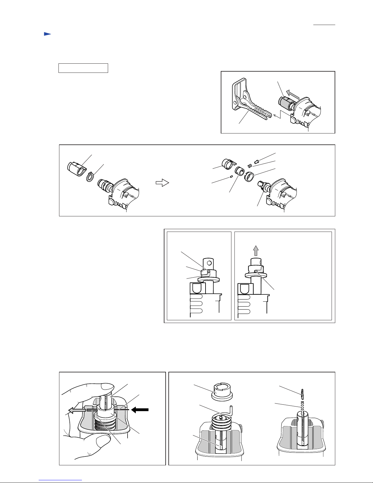
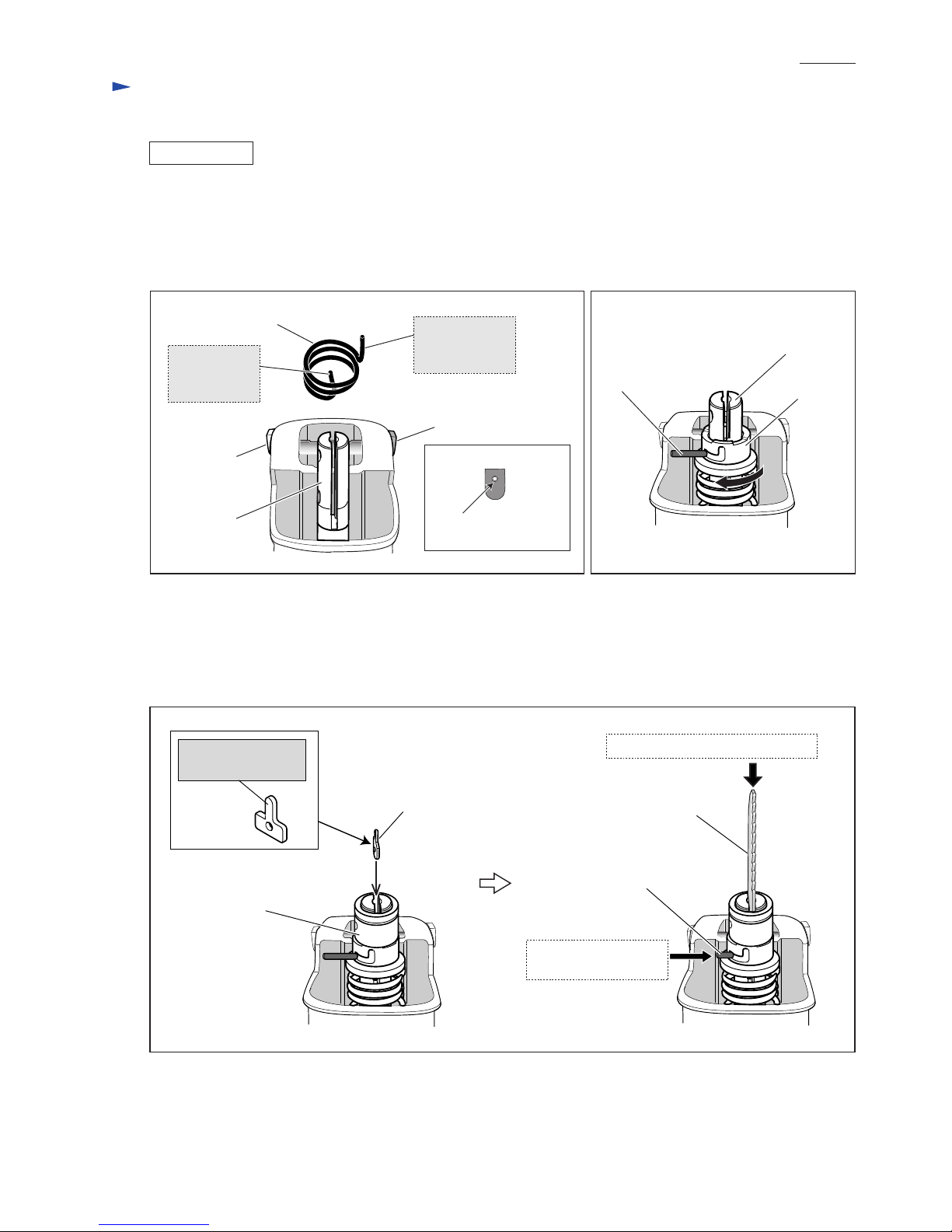
Fig. 12
5) While fitting the two projections of driving sleeve in the concavities of sleeve, push driving sleeve into gear housing.
At this time, turn driving sleeve clockwise so that the protruding portion of driving sleeve cannot be interfered by
gear housing. After driving sleeve is pushed into gear housing to the full, turn driving sleeve clockwise to lock pin 3
in place. (Fig. 12)
Note: Driving sleeve is used as a jig to lock pin 3 in place, not assembled to slider in this step.
6) Remove driving sleeve.
7) Assemble the following parts to slider (Refer to Fig. 5.):
Driving sleeve guide, Guide sleeve, Pin 3 (of 6mm length), Shoulder pin 5, Compression spring 6
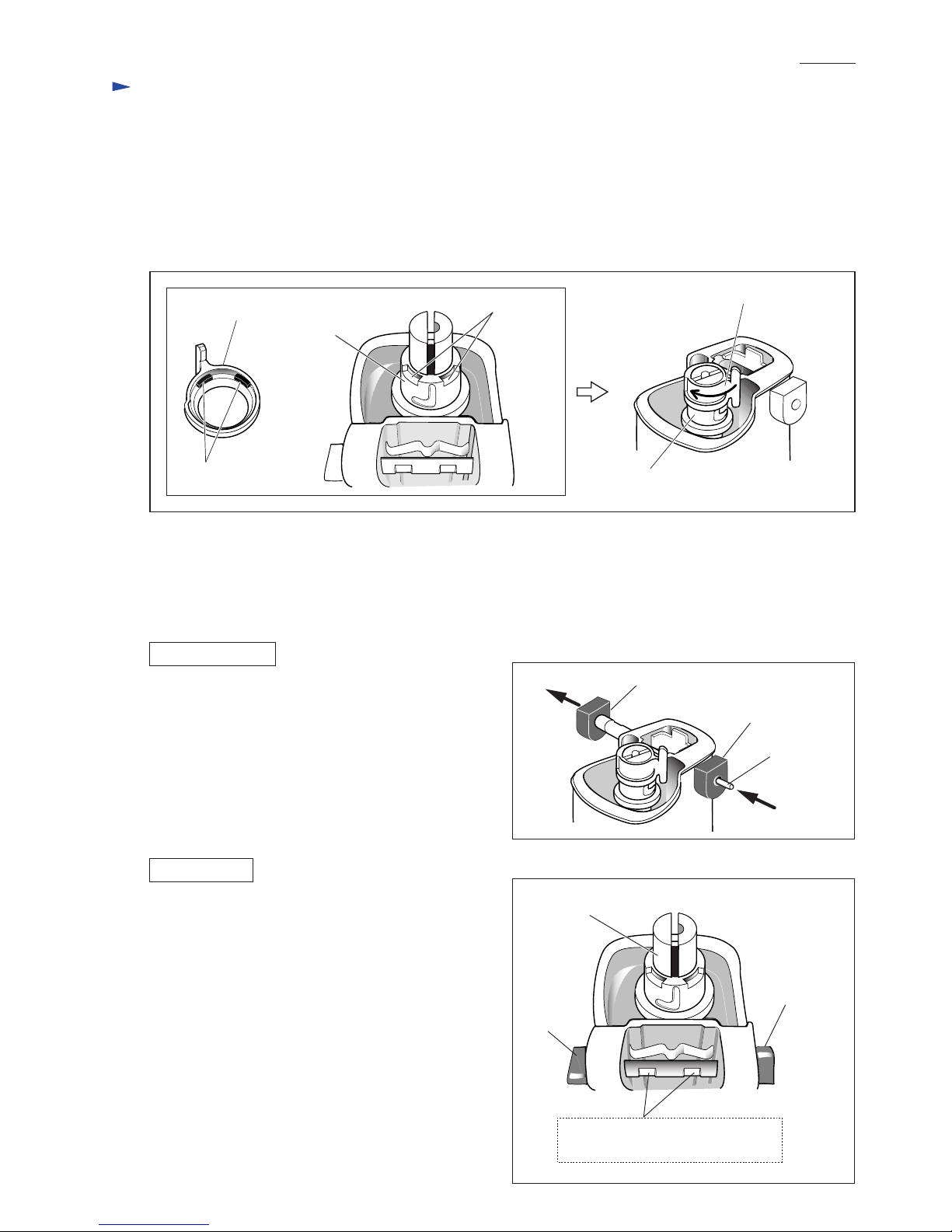
8) Put driving sleeve over guide sleeve and secure it with retaining ring S-18 using 1R291. Then cover driving sleeve
with protector. (When installing driving sleeve, fit its projections in the concavities of sleeve and driving sleeve guide.)
Projections
Concavities
Driving sleeve Driving sleeve
Sleeve
Sleeve
[3] -2. Replacing Shift Button and Cap
Shift button can be removed from gear housing cover by
inserting a thin bar into the hole of cap and push the bar.
(Fig. 13)
DISASSEMBLING
ASSEMBLING
Fig. 13
Shift button
thin bar
Cap
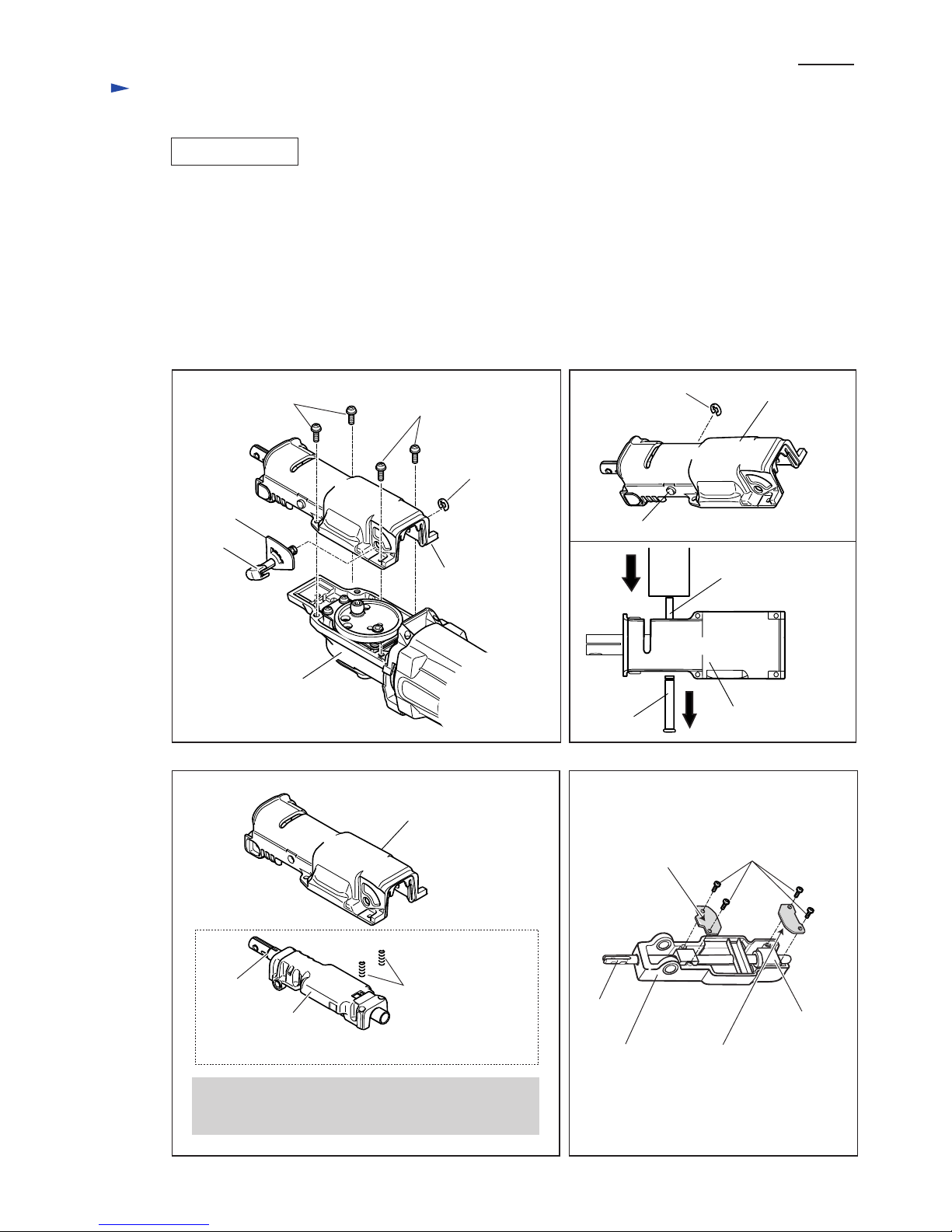
Fig. 14
1) Replace cap by new one because removal of shift button
damages the inside surface of cap.
2) From shift button, remove all the plastic dust scraped off
the removed cap. Insert shift button through the holes in
the both sides of gear housing cover.
And then press-fit shift button in the new cap by hand.
Important:
Be sure to assemble shift button to gear housing cover
so that the two notches of shift button face the side
opposite to slider as illustrated in Fig. 14.
These notches of shift button must
face the side opposite to slider.
Slider
Shift button
Cap