IMG STAGE LINE LC-324DMX User manual

ELECTRONICS FOR SPECIALISTS ELECTRONICS FOR SPECIALISTS ELECTRONICS FOR SPECIALISTS ELECTRONICS FOR SPECIALISTS
BEDIENUNGSANLEITUNG
INSTRUCTION MANUAL
MODE D’EMPLOI
ISTRUZIONI PER L’USO
GEBRUIKSAANWIJZING
MANUAL DE INSTRUCCIONES
INSTRUKCJA OBSŁUGI
SIKKERHEDSOPLYSNINGER
SÄKERHETSFÖRESKRIFTER
TURVALLISUUDESTA
LC-324DMX
Bestell-Nr. • Order No. 38.7720
DMX-Lichtsteuerpult
für LED-Scheinwerfer
DMX Controller
for LED Spotlights

ELECTRONICS FOR SPECIALISTS ELECTRONICS FOR SPECIALISTS ELECTRONICS FOR SPECIALISTS ELECTRONICS FOR SPECIALISTS
2
Deutsch .......... Seite 4
English ........... Page 10
Français .......... Page 16
Italiano........... Pagina 22
Nederlands ....... Pagina 28
Español .......... Página 34
Polski ............ Strona 40
Dansk ............ Sida 46
Svenska .......... Sidan 46
Suomi............ Sivulta 47

3
PATCH MODE8 CHANNELS5 CHANNELS
7 CHANNELS4 CHANNELS
6 CHANNELS3 CHANNELS
12
PANTONE cool-grey 5C
MIC SENS.
SOUND
FADER
FLASH
BLACK OUT
RED GREEN BLUE WHITE MASTER STROBE
100
ON
OFF
50
0
100
50
0
% %
POWER
LIGHT RED ORANGE YELLOWRED
LIGHT GREEN CYAN WHITEGREEN
LIGHT BLUE MAGENTA PURPLEBLUE
3 COLOUR STROBE COL. FADE12 COLOUR
2 3 41
2 3 41
6 7 85
PROGRAM
COLOUR
FIXTURE
GREEN STROBE
BLUE MASTER
WHITE
T+ T−
RED
1
3
5
6
7
8
9
10
11
2
4
21 3
PUSH
DMX OUT
9-12 V
13 14
➀
➂
➁

4
Referenz für Sprachkennzeichnung der Seiten und Inhaltsverzeichnis
Referenz für Sprachen-Inhaltsverzeichnis
Deutsch
Deutsch
Deutsch Seite
Inhalt DMX-Lichtsteuerpult
für LED-Scheinwerfer
Diese Anleitung richtet sich an den Installa-
teur des Geräts mit Grundkenntnissen in der
DMX-Steuerung und an den Bediener. Bitte
lesen Sie die Anleitung vor dem Betrieb gründ-
lich durch und heben Sie sie für ein späteres
Nachlesen auf.
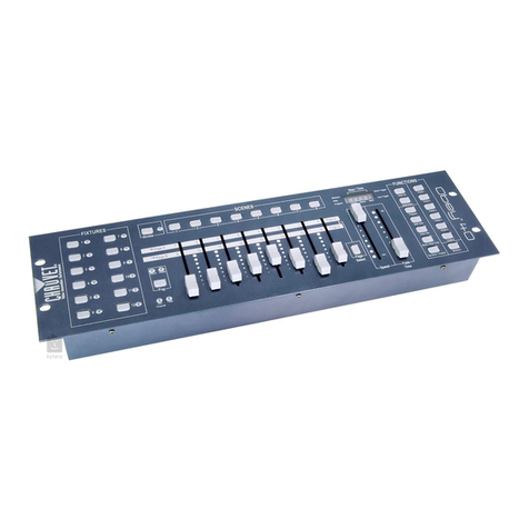
Auf der ausklappbaren Seite 3 finden Sie alle
beschriebenen Bedienelemente und Anschlüsse.
1 Übersicht der Bedienelemente
und Anschlüsse
1
Tasten FIXTURE zum An- und Abwählen der
einzustellenden Scheinwerfer sowie für die
Zuordnung der DMX-Kanäle
2 Tasten COLOUR zur Farbwahl für die ange-
wählten Scheinwerfer sowie für die Zuord-
nung der DMX-Funktionen
Über die Tasten mit der zusätzlichen Be-
schriftung T+ und T− ist ein Tempoände-
rung der Farbwechselprogramme und des
Stroboskopeffekts möglich.
3
Tasten PROGRAM zum Aufruf eines Farb-
wechselprogramms oder des Stroboskop-
effekts sowie für die Zuordnung der DMX-
Kanäle
4
Schieberegler (Fader) zur manuellen Einstel-
lung der Farben sowie zum Bedienen der
scheinwerfereigenen Funktionen MASTER
und STROBE
5
Mikrofon für musikgesteuerte Farbwechsel-
programme
6 Regler MIC SENS zur Einstellung der Mikro-
fonempfindlichkeit
7 Ein-/Ausschalter POWER
8
Taste SOUND zum Ein- und Ausschalten der
Musiksteuerung für die Programme 12CO-
LOUR und 3COLOUR
9 Taste FADER zum Aktivieren und Deaktivie-
ren der Fader (4)
1 Übersicht der Bedienelemente und
Anschlüsse � � � � � � � � � � � � � � � � � � 4
2 Hinweise fürdensicherenGebrauch � � � 5
3 Einsatzmöglichkeiten � � � � � � � � � � � � 5
4 Inbetriebnahme � � � � � � � � � � � � � � � 6
4�1 Gerät aufstellen � � � � � � � � � � � � � � � � 6
4�2 Scheinwerfer anschließen � � � � � � � � � � � 6
4�3 Stromversorgung herstellen � � � � � � � � � � 6
4�4 Voreinstellungen � � � � � � � � � � � � � � � � 6
4�4�1 Anzahl der DMX-Kanäle einstellen� � � � � � 6
4�4�2 Startadressen einstellen � � � � � � � � � � � 7
4�4�3 Kanalfunktionen zuordnen� � � � � � � � � � 7
5 Bedienung � � � � � � � � � � � � � � � � � � 7
5�1 Farbwechselprogramme � � � � � � � � � � � � 8
5�1�1 Musiksteuerung � � � � � � � � � � � � � � � 8
5�2 Stroboskopeffekt � � � � � � � � � � � � � � � � 8
5�3 Geschwindigkeit für Programme oder
Stroboskopeffekt ändern � � � � � � � � � � � � 8
5�4 Flash-Funktion � � � � � � � � � � � � � � � � � 9
5�5 Blackout-Funktion � � � � � � � � � � � � � � � 9
5�6 Licht beim Einschalten � � � � � � � � � � � � � 9
6 Technische Daten � � � � � � � � � � � � � � 9

5
Deutsch
10 Taste FLASH schaltet alle zugeordneten Ka-
näle aller angewählten Scheinwerfer auf den
Maximalwert, solange die Taste gedrückt
wird
11 Taste BLACKOUT schaltet alle Kanäle aller
Scheinwerfer auf Null (dunkel) und wieder
zurück auf die vorherigen Werte
12
Schalter zum Anpassen des Pultes an den
verwendeten Scheinwerfertyp
13
Stromversorgungsbuchse zum Anschluss des
beiliegenden Netzgeräts
14 DMX-Signal-Ausgang (3-pol. XLR) zum An-
schluss an den DMX-Eingang des ersten
Scheinwerfers
2 Hinweise
fürdensicherenGebrauch
Die Geräte (Steuerpult und Netzgerät) entspre-
chen allen relevanten Richtlinien der EU und sind
deshalb mit gekennzeichnet.
WARNUNG
Das Netzgerät wird mit lebens-
gefährlicher Netzspannung
versorgt. Nehmen Sie deshalb
niemals selbst Eingriffe daran
vor. Es besteht die Gefahr
eines elektrischen Schlages.
•
Verwenden Sie die Geräte nur im Innenbe-
reich und schützen Sie sie vor Tropf- und
Spritzwasser sowie vor hoher Luftfeuchtig-
keit. Der zulässige Einsatztemperaturbereich
beträgt 0–40°C.
•
Nehmen Sie das Pult nicht in Betrieb und zie-
hen Sie sofort das Netzgerät aus der Steck-
dose,
1. wenn sichtbare Schäden an einem der Ge-
räte vorhanden sind,
2.
wenn nach einem Sturz oder Ähnlichem der
Verdacht auf einen Defekt besteht,
3. wenn Funktionsstörungen auftreten.
Geben Sie die Geräte in jedem Fall zur Repa-
ratur in eine Fachwerkstatt.
•
Verwenden Sie für die Reinigung nur ein tro-
ckenes, weiches Tuch, niemals Wasser oder
Chemikalien.
•
Werden die Geräte zweckentfremdet, falsch
angeschlossen oder nicht fachgerecht repa-
riert, kann keine Haftung für daraus resultie-
rende Sach- oder Personenschäden und keine
Garantie für die Geräte übernommen werden.
Sollen die Geräte endgültig aus dem
Betrieb genommen werden, übergeben
Sie sie zur umweltgerechten Entsorgung
einem örtlichen Recyclingbetrieb.
3 Einsatzmöglichkeiten
Das Lichtsteuerpult LC-324DMX dient zur einfa-
chen, unabhängigen DMX-Steuerung von bis zu
vier LED-Scheinwerfern oder Scheinwerfergrup-
pen mit gleichen Kanalfunktionen. Es können
Scheinwerfer mit 3–8 DMX-Kanälen verwendet
werden. Das Pult unterstützt folgende Schein-
werferfunktionen:
RED = Helligkeit der roten LEDs
GREEN = Helligkeit der grünen LEDs
BLUE = Helligkeit der blauen LEDs
WHITE = Helligkeit der weißen LEDs
MASTER = Gesamthelligkeit (Dimmer)
STROBE = Stroboskopeffekt
Hinweis: Welche Funktionen tatsächlich verfügbar sind,
hängt vom Scheinwerfertyp ab.
Für jeden Scheinwerfer lässt sich am Steuer-
pult eine von 12 voreingestellten Farben wäh-
len oder eine individuelle Farbmischung über
die Regler einstellen. Zusätzlich bietet das Pult
zwei Farbwechselprogramme mit wählbarer Ge-
schwindigkeit, die über das integrierte Mikrofon
auch musiksynchron ablaufen können, und ein
Programm mit Farbüberblendungen. Über das
Stroboskop-Programm ist ein Stroboskopeffekt
auch mit Scheinwerfern möglich, die nicht über
eine eigene Stroboskopfunktion verfügen.

6
Deutsch
4 Inbetriebnahme
4.1 Gerät aufstellen
Das Gerät auf einer ebenen Fläche aufstellen.
Es kann bei Bedarf auch über die Löcher in der
Frontplatte z.B. in einem Rack montiert werden.
4.2 Scheinwerfer anschließen
Als DMX-Schnittstelle besitzt das Gerät einen
3-poligen XLR-Anschluss mit folgender Kontakt-
belegung:
Pin 1 = Masse, Pin 2 = DMX−, Pin 3 = DMX+
Zum Anschluss sollten spezielle Kabel für die
DMX-Signalübertragung verwendet werden
(z.B. Kabel der CDMXN-Serie). Bei Leitungs-
längen ab 150m oder bei der Steuerung von
mehr als 32 Geräten über einen DMX-Ausgang
wird grundsätzlich das Zwischenschalten eines
DMX-Aufholverstärkers empfohlen (z. B. SR-
103DMX).
Hinweis: Es können auch mehr als vier Scheinwer-
fer an das Pult angeschlossen werden. Dabei werden
die einzelnen Scheinwerfer allein durch die Einstellung
ihrer Startadresse einer der vier Scheinwerfergruppen
zugeordnet. Die Anschlussreihenfolge ist dabei ohne
Bedeutung.
1)
Den Steuereingang des ersten Scheinwerfers
mit dem Ausgang DMX OUT (14) des Pultes
verbinden.
2)
Den Steuerausgang des ersten Scheinwerfers
mit dem Steuereingang des nächsten Schein-
werfers verbinden. Dessen Ausgang wieder
mit dem Eingang des nachfolgenden Schein-
werfers verbinden usw., bis alle Scheinwerfer
in einer Kette angeschlossen sind.
3)
Um Störungen bei der Signalübertragung
auszuschließen, sollte bei langen Leitungen
oder bei einer Vielzahl von hintereinander-
geschalteten Scheinwerfern der Steueraus-
gang des letzten Scheinwerfers der Kette mit
einem 120-Ω-Widerstand (> 0,3 W) abge-
schlossen werden: In die Ausgangsbuchse
einen entsprechenden Abschlussstecker (z.B.
DLT-123) stecken.
4.3 Stromversorgung herstellen
Das beiliegende Steckernetzgerät zuerst mit
der Buchse 9–12 V (13) verbinden und dann
das Netzgerät in eine Steckdose (230V/50Hz)
stecken.
4.4 Voreinstellungen
Durch die Voreinstellungen wird das Steuerpult
an die Eigenschaften der Scheinwerfer angepasst.
Die Scheinwerfer müssen so eingestellt werden,
dass sie unabhängig oder in Gruppen gesteuert
werden können. Optimal ist die Verwendung
von Scheinwerfern gleichen Typs. Unterschied-
liche Scheinwerfertypen können nur zusammen
verwendet werden, wenn sie über die gleiche
Anzahl von Kanälen und dieselben Kanalfunk-
tionen verfügen.
4.4.1 Anzahl der DMX-Kanäle einstellen
Es gibt Scheinwerfer mit einer unterschiedlicher
Anzahl von Steuerkanälen. Bei vielen Schein-
werfern kann zwischen mehreren Betriebsarten
mit unterschiedlicher Kanalanzahl umgeschaltet
werden.
1) Bei Scheinwerfern mit mehreren Betriebsar-
ten die Betriebsart wählen, bei der die Grund-
farben einzeln gesteuert werden können und
möglichst ein eigener Kanal für die Gesamt-
helligkeit und einen Stroboskopeffekt vor-
handen ist (☞Anleitung der Scheinwerfer).
2)
Am Steuerpult die Kanalanzahl des einzel-
nen Scheinwerfers einstellen. Dazu bei aus-
geschaltetem Pult nach folgender Tabelle die
Schalter 2– 4 (12) auf der Vorderseite des
Pultes einstellen.
Kanalanzahl Schalterpositionen
3
4
5
6
7
8
Das Pult berechnet aus der eingestellten Kanal-
anzahl die Startadressen für die Scheinwerfer
2 bis 4.

7
Deutsch
4.4.2 Startadressen einstellen
An allen Scheinwerfern (FIXTURE) oder Schein-
werfergruppen nach folgender Tabelle die Start-
adressen einstellen (
☞
Anleitung der Schein
-
werfer).
Kanal-
anzahl Startadressen
FIXTURE 1 FIXTURE 2 FIXTURE 3 FIXTURE 4
3 1 4 7 10
4 1 5 9 13
5 1 6 11 16
6 1 7 13 19
7 1 8 15 22
8 1 9 17 25
4.4.3 Kanalfunktionen zuordnen
Der Umfang und die Reihenfolge der Funktionen
variiert zwischen Scheinwerfertypen. Deshalb
lässt sich das Pult auf die Kanalfunktionen des
verwendeten Scheinwerfertyps einstellen.
1)
Den Schalter (12) mit der Nr. 1 bei ausge-
schaltetem Pult in die obere Position bringen:
Hinweis: Die Position der anderen drei
Schalter sind hierfür ohne Bedeutung.
2)
Das Pult mit dem Schalter POWER (7) ein-
schalten (Position ON). Es befindet sich jetzt
im Zuordnungsmodus (patch mode).
3) Zum Löschen aller vorherigen Zuordnungen
die Taste BLACKOUT (11) drücken. Die LED
der Taste blinkt zur Bestätigung auf.
4)
Für alle vom Pult unterstützten Funktionen
des Scheinwerfers nun nacheinander jeweils
die Kanalnummer und die Kanalfunktion ein-
geben. Dafür ist nur die unter den Tasten
stehende Funktion von Bedeutung:
Mit den Tasten 1–4 (1) und 5– 8 (3) die
Kanalnummer wählen. Dann die zugehörige
Kanalfunktion mit den Tasten COLOUR (2)
bestimmen: RED, GREEN, STROBE, WHITE,
BLUE, MASTER.
Beispiel: Um die Funktion „Helligkeit der roten
LEDs“ dem Kanal 2 zuzuordnen, erst die Taste „2“
drücken, dann die Taste „RED“.
Nach jeder Zuordnung blinken die LEDs zur
Bestätigung auf.
Hinweis: Für die Kanäle eines Scheinwerfers, denen
keine Funktion zugeordnet wurde, sendet das Pult
im Betrieb stets den Wert Null.
5) Den Schalter mit der Nr. 1 für den normalen
Betrieb wieder in die untere Position stellen:
Hinweis: Die anderen Schalter in der
Einstellung von Kap. 4.4.1 belassen.
6)
Das Pult mit dem Schalter POWER (7) aus-
schalten.
5 Bedienung
1)
Das Pult mit dem Schalter POWER (7) ein-
schalten (Position ON).
2) Mit den Tasten FIXTURE (1) die einzustellen-
den Scheinwerfer an- oder abwählen. Die
LED einer Taste leuchtet bei angewähltem
Scheinwerfer.
3) Mit den Tasten COLOUR (2) eine Farbe wäh-
len oder die Taste FADER (9) drücken und mit
den Reglern (4) eine individuelle Einstellung
vornehmen.
Hinweis: Die Verfügbarkeit der einzelnen Regler-
funktionen hängt vom verwendeten Scheinwerfer-
typ und von der Zuordnung zu den Kanalfunktionen
(☞Kapitel 4.4.3) ab.
4)
Nach Bedarf weitere Scheinwerfer anwählen
und einstellen. Ein abgewählter Scheinwerfer
behält seine Einstellung bei.
5) Wenn gewünscht, automatische Farbwech-
selprogramme aufrufen (☞Kapitel 5.1) oder
spezielle Effekte einsetzen:
STROBE (Kapitel 5.2)
FLASH (Kapitel 5.4)
BLACKOUT (Kapitel 5.5)
6)
Nach dem Gebrauch das Pult mit dem Schal-
ter POWER wieder ausschalten. Das Netz-
gerät verbraucht auch bei ausgeschaltetem
Lichtsteuerpult einen geringen Strom. Des-
halb zur Vermeidung unnötigen Stromver-
brauchs bei längeren Nutzungspausen das
Netzgerät vom Netz trennen.

8
Deutsch
5.1 Farbwechselprogramme
Das Lichtsteuerpult verfügt über drei automati-
sche Programme. Zum Aufruf eines Programms:
1) Mit den Tasten FIXTURE (1) die betreffenden
Scheinwerfer an- oder abwählen. Die LED
der Taste leuchtet bei angewähltem Schein-
werfer.
2) Mit den Tasten PROGRAM eines der drei fol-
genden Programme wählen:
12 COLOUR = Farbwechsel mit 12 Farben
3 COLOUR = Farbwechsel mit 3 Farben
COL. FADE = Farbüberblendungen mit
7Farben
3)
Bei Bedarf die Geschwindigkeit des Pro-
gramms mit den Tasten T+ und T− (2) ändern
(☞Kapitel 5.3).
4)
Zum Beenden des Programms die Programm-
taste erneut drücken oder ein anderes Pro-
gramm wählen.
Das Programm wird nur von den aktuell ange-
wählten Scheinwerfern ausgeführt. Bei Abwahl
eines Scheinwerfers während eines Programms
behält dieser die letzte Einstellung.
5.1.1 Musiksteuerung
Die beiden Farbwechselprogramme 12COLOUR
und 3COLOUR können auch über das einge-
baute Mikrofon (5) synchron zum Rhythmus
laufender Musik gesteuert werden.
1) Das Programm 12COLOUR oder 3 COLOUR
aufrufen (☞Kapitel 5.1).
2)
Die Taste SOUND (8) drücken. Die LED der
Taste leuchtet jetzt und die Musiksteuerung
ist aktiv.
3)
Bei Bedarf die Empfindlichkeit des Mikrofons
mit dem Regler MIC SENS (6) an die Laut-
stärke der Musik anpassen.
4)
Zum Deaktivieren der Musiksteuerung die
Taste SOUND erneut drücken.
5.2 Stroboskopeffekt
Nicht jeder Scheinwerfer verfügt über einen
eigenen Strobe-Kanal, deshalb bietet das Pult
auch einen Stroboskopeffekt. Anders als die
Farbwechselprogramme wirkt der Stroboskop-
effekt nicht nur auf die angewählten Scheinwer-
fer, sondern auf alle Scheinwerfer.
1)
Wie am Anfang von Kapitel 5beschrieben ist,
für alle Scheinwerfer die gewünschten Farb-
oder Helligkeitseinstellungen vornehmen.
2) Im Bereich PROGRAM (3) die Taste STROBE
drücken. Die LED der Taste leuchtet.
3) Bei Bedarf die Blitzhäufigkeit mit den Tasten
T+ und T− (2) ändern (☞Kapitel 5.3).
4)
Zum Beenden des Stroboskopeffekts die
Taste STROBE erneut drücken.
5.3 Geschwindigkeit für Programme
oder Stroboskopeffekt ändern
Für ein Farbwechselprogramm oder den Stro-
boskopeffekt kann die Geschwindigkeit geän-
dert werden. Dazu während des Programms
oder bei aktivem Stroboskopeffekt im Bereich
COLOUR (2) die Taste T− drücken, um die
Geschwindigkeit zu erhöhen oder die Taste
T+, um die Geschwindigkeit zu verringern. Die
aktuell eingestellte Schrittdauer bzw. die Zeit
zwischen den Blitzen wird dabei für kurze Zeit
mit den oberen beiden Reihen der grünen LEDs
im Binärformat angezeigt:
LIGHT RED ORANGE YELLOWRED
LIGHT GREEN CYAN WHITE
2 2 2 2 2 2 2 2
GREEN
LIGHT BLUE MAGENTA PURPLEBLUE
GREEN STROBE
BLUE MASTER
WHITE
T+
T−
RED
Anzeige Einstellbereich
3 COLOUR
12 COLOUR COL. FADE
1 min/Farbe 37 s/Farbe
⋮ ⋮ ⋮
0,25 s/Farbe 0,2 s/Farbe
Anzeige Einstellbereich
STROBE
0,8 Blitze/s
⋮ ⋮
16 Blitze/s
Hinweis: Die Geschwindigkeitsänderung geschieht um
die Dauer eines Programmschritts verzögert (max. 1min).

9
Deutsch
5.4 Flash-Funktion
Mit der Taste FLASH (10) können kurzfristig die
Kanäle aller angewählten Scheinwerfer auf den
Maximalwert geschaltet werden. Mit dem Los-
lassen der Taste erhalten alle Kanäle wieder ihren
vorherigen Wert.
Hinweis: Die Flash-Funktion kann nicht zusammen mit
dem pulteigenen Stroboskopeffekt (
☞
Kapitel 5.2) ver-
wendet werden.
5.5 Blackout-Funktion
Zum Dunkelschalten aller Scheinwerfer die Taste
BLACK OUT (11) drücken. Die LED der Taste
leuchtet zur Kontrolle. Zum Wiedereinschalten
der Scheinwerfer die Taste erneut drücken.
5.6 Licht beim Einschalten
Es kann festgelegt werden, welche Scheinwerfer
beim Einschalten des Pultes leuchten sollen und
mit welchem Licht:
1)
Mit den Tasten FIXTURE (1) alle Scheinwerfer
anwählen, die nach jedem Einschalten des
Pultes leuchten sollen.
2)
Die Taste FADER (9) drücken und mit den
Reglern (4) die gewünschten Einstellungen
vornehmen.
Alternativ ein Programm wählen (☞Kapitel
5.1), das über die angewählten Scheinwerfer
ablaufen soll.
3)
Zum Speichern die Taste LIGHT BLUE (2) und
die Taste FLASH (10) gleichzeitig drücken.
Acht grüne LEDs blinken zur Bestätigung auf.
6 Technische Daten
Datenprotokoll: � � � � � � � � �DMX 512
Anzahl der DMX-Kanäle: � � max� 4 × 6 aus 32 Kanälen
Stromversorgung: � � � � � � �⎓9 – 12V über beilie-
gendes Netzgerät an
230V/50 Hz
Einsatztemperatur:� � � � � � �0 – 40 °C
Abmessungen:� � � � � � � � � � 242 × 156 × 62 mm
Gewicht: � � � � � � � � � � � � � �1,5 kg
Änderungen vorbehalten.
Diese Bedienungsanleitung ist urheberrechtlich für MONACOR
®INTERNATIONAL GmbH & Co. KG geschützt.
Eine Reproduktion für eigene kommerzielle Zwecke – auch auszugsweise – ist untersagt.

10
Referenz für Sprachkennzeichnung der Seiten und Inhaltsverzeichnis
Referenz für Sprachen-Inhaltsverzeichnis
English
English
English Page
Contents
DMX Controller for LED Spotlights
These instructions are intended for installers of
the controller with basic knowledge in DMX
control and for users. Please read the instruc-
tions carefully prior to operation and keep them
for later reference.
All operating elements and connections
described can be found on the fold-out page 3.
1 Operating Elements
andConnections
1
Buttons FIXTURE to select/deselect the spot-
lights to be adjusted and to assign DMX
channels
2
Buttons COLOUR to select the colours for
the spotlights selected and to assign DMX
functions
The buttons marked with T+ and T– can
be used to modify the speed of the colour
change programs and of the strobe effect.
3
Buttons PROGRAM to call up a colour
change program or the strobe effect and
to assign DMX channels
4
Faders to set the colours manually and to
operate the functions MASTER and STROBE
of the spotlights
5
Microphone for music-controlled colour
change programs
6
Control MIC SENS to set the microphone
sensitivity
7 POWER switch
8
Button SOUND to activate/deactivate the
music control for the programs 12 COLOUR
and 3 COLOUR
1 Operating Elements andConnections � � 10
2 Safety Notes � � � � � � � � � � � � � � � � 11
3 Applications � � � � � � � � � � � � � � � � 11
4 Before Operation � � � � � � � � � � � � � 12
4�1 Setting up � � � � � � � � � � � � � � � � � � 12
4�2 Connecting the spotlights � � � � � � � � � � 12
4�3 Power supply� � � � � � � � � � � � � � � � � 12
4�4 Presets� � � � � � � � � � � � � � � � � � � � 12
4�4�1 Setting the number of DMX channels � � � 12
4�4�2 Setting the start addresses� � � � � � � � � 13
4�4�3 Assigning the channel functions � � � � � � 13
5 Operation � � � � � � � � � � � � � � � � � 13
5�1 Colour change programs � � � � � � � � � � � 14
5�1�1 Music control � � � � � � � � � � � � � � � 14
5�2 Strobe effect � � � � � � � � � � � � � � � � � 14
5�3 Modifying the speed of programs and the speed
of the strobe effect� � � � � � � � � � � � � � 14
5�4 Flash function � � � � � � � � � � � � � � � � 15
5�5 Blackout function � � � � � � � � � � � � � � 15
5�6 Spotlight illumination when switching on the
controller � � � � � � � � � � � � � � � � � � 15
6 Specifications � � � � � � � � � � � � � � � 15

11
English
9
Button FADER to activate/deactivate the
faders (4)
10
Button FLASH; while this button is kept
pressed, any channels assigned to any spot-
lights selected will be set to their maximum
values
11 Button BLACK OUT to set any channels of
any spotlights to zero (blackout) and back
to the previous values
12 Switches to set the controller to the type of
spotlight used
13
Power supply jack to connect the power
supply unit provided
14
DMX signal output (3-pole XLR) for connec-
tion to the DMX input of the first spotlight
2 Safety Notes
The units (controller and power supply unit) cor-
respond to all relevant directives of the EU and
are therefore marked with .
WARNING
The power supply unit uses
dangerous mains voltage.
Leave servicing to skilled per-
sonnel only. Inexpert handling
of the unit may result in elec-
tric shock.
•
The units are suitable for indoor use only. Pro-
tect them against dripping water, splash water
and high air humidity. The admissible ambient
temperature range is 0– 40 °C.
•
Do not operate the controller and immedi-
ately disconnect the power supply unit from
the socket
1. if one of the units is visibly damaged,
2. if a defect might have occurred after a unit
was dropped or suffered a similar accident,
3. if malfunctions occur.
In any case, the units must be repaired by
skilled personnel.
•
For cleaning only use a dry, soft cloth; never
use water or chemicals.
•
No guarantee claims for the units and no
liability for any resulting personal damage or
material damage will be accepted if the units
are used for other purposes than originally
intended, if they are not correctly connected,
or if they are not repaired in an expert way.
If the units are to be put out of oper-
ation definitively, take them to a local
recycling plant for a disposal which is
not harmful to the environment.
3 Applications
The controller LC-324DMX is used for easy and
independent DMX control of up to four LED
spotlights or spotlight groups with the same
channel functions. Spotlights with 3 – 8 DMX
channels can be used. The controller supports
the following spotlight functions:
RED = brightness of red LEDs
GREEN = brightness of green LEDs
BLUE = brightness of blue LEDs
WHITE = brightness of white LEDs
MASTER = total brightness (dimmer)
STROBE = strobe effect
Note: The functions available depend on the type of
spotlight used.
For each spotlight, one of 12 preset colours can
be selected on the controller. Alternatively, an
individual colour mix can be adjusted via con-
trols. In addition, the controller offers two colour
change programs with selectable speed (these
programs can also be music-controlled via the
internal microphone) and a program with col-
our fading. The strobe program allows strobe
effects even for spotlights without internal
strobe function.

12
English
4 Before Operation
4.1 Setting up
Set up the controller on a flat surface. Via holes
on the front panel, the controller can also be
installed (e.g. in a rack), if required.
4.2 Connecting the spotlights
The DMX interface of the controller is a 3-pole
XLR connector with the following pin config-
uration:
Pin 1 = ground, Pin 2 = DMX−, Pin 3 = DMX+
For connection, special cables for DMX signal
transmission are recommended (e. g. cables
from the CDMXN series). For cable lengths ex-
ceeding 150m or when controlling more than
32 units via a single DMX output, it is generally
recommended to insert a DMX level matching
amplifier (e.g. SR-103DMX).
Note: It is even possible to connect more than four spot-
lights to the controller: Simply set their start addresses
and the individual spotlights will be assigned to one
of the four spotlight groups. The order of connection
is irrelevant.
1) Connect the control input of the first spot-
light to the output DMX OUT (14) of the
controller.
2)
Connect the control output of the first
spotlight to the control input of the second
spotlight. Connect the output of the second
spotlight to the input of the third spotlight
etc. until all spotlights have been connected
in a chain.
3)
To prevent interference in signal transmis-
sion, in case of long cables or a multitude
of spotlights connected in series, terminate
the control output of the last spotlight in
the chain with a 120Ω resistor (> 0.3W):
Connect a corresponding terminating plug
(e.g. DLT-123) to the output jack.
4.3 Power supply
Connect the plug-in power supply unit to the
jack 9–12V (13) first, then connect the power
supply unit to a mains socket (230V/50Hz).
4.4 Presets
The presets will match the controller to the
characteristics of the spotlights. The spotlights
must be set to independent control or control in
groups. It is ideal to use spotlights of the same
type. Different types of spotlights can only be
used together if they offer the same number of
channels and the same channel functions.
4.4.1 Setting the number of DMX channels
There are spotlights with different numbers of
control channels. Many spotlights offer multi-
ple operating modes with different numbers
of channels.
1)
Spotlights with multiple operating modes:
Select the operating mode which allows in-
dividual control of the primary colours and
which offers a separate channel for total
brightness and for a strobe effect, if available
(☞manual of the spotlights).
2)
On the controller, set the number of channels
of the individual spotlight: While the control-
ler is still switched off, set the switches 2– 4
(12) on its front according to the table below.
Number of channels Switch positions
3
4
5
6
7
8
On the basis of the number of channels adjust-
ed, the controller will calculate the start address-
es for the spotlights 2 to 4.

13
English
4.4.2 Setting the start addresses
Set the start addresses of all spotlights (FIXTURE)
or spotlight groups according to the table below
(☞manual of the spotlights).
Number of
channels Start addresses
FIXTURE 1 FIXTURE 2 FIXTURE 3 FIXTURE 4
3 1 4 7 10
4 1 5 9 13
5 1 6 11 16
6 1 7 13 19
7 1 8 15 22
8 1 9 17 25
4.4.3 Assigning the channel functions
Different types of spotlights vary in the extent
and the sequence of functions. Therefore, the
controller can be set to the channel functions
of the type of spotlight used.
1) While the controller is still switched off, set
switch 1 of the switch group (12) to the
upper position.
Note: The positions of the other three
switches are irrelevant in this case.
2) Use the POWER switch (7) to switch on the
controller. The controller is now in the assign
mode (patch mode).
3)
To delete any previous assignments, press the
button BLACK OUT (11). The LED of the but-
ton will briefly flash to confirm the process.
4)
For all functions of the spotlight supported by
the controller, enter the channel number and
the channel function one after another. Only
the function indicated below the buttons is
relevant in this case:
Use the buttons 1–4 (1) and 5–8 (3) to select
the channel number. Then use the buttons
COLOUR (2) to define the corresponding
channel function: RED, GREEN, STROBE,
WHITE, BLUE, MASTER.
Example: To assign the function “brightness of red
LEDs” to channel 2, first press the button “2” and
then the button “RED”.
After each assignment, the LEDs will flash to
confirm the process.
Note: For any channel of a spotlight to which no
function has been assigned, the controller will al-
ways send the value zero during operation.
5)
For normal operation, set switch 1 to the
lower position again.
Note: Do not change the settings of the
other switches made in chapter 4.4.1.
6)
Switch off the controller with the POWER
switch (7).
5 Operation
1) Use the POWER switch (7) to switch on the
controller.
2) Use the buttons FIXTURE (1) to select/dese-
lect the spotlights to be adjusted. When a
spotlight has been selected, the LED of the
corresponding button will light up.
3) Use the buttons COLOUR (2) to select a col-
our or press the button FADER (9) and use
the controls (4) for an individual adjustment.
Note: The availability of individual control functions
depends on the type of spotlight used and on the
assignment to the channel functions (☞ chap-
ter4.4.3).
4)
Select and adjust further spotlights as de-
sired. If a spotlight is deselected, it will retain
its current setting.
5) If desired, call up automatic colour change
programs (☞chapter 5.1) or use special
effects:
STROBE (chapter 5.2)
FLASH (chapter 5.4)
BLACK OUT (chapter 5.5)
6) After use, switch off the controller with the
POWER switch. The power supply unit will
still consume some power when the con-
troller has been switched off. To prevent
unnecessary power consumption, always
disconnect the power supply unit from the
mains if the controller is not used for a longer
period of time.

14
English
5.1 Colour change programs
The controller offers three automatic programs.
To call up a program:
1) Use the buttons FIXTURE (1) to select/dese-
lect the corresponding spotlights. When a
spotlight has been selected, the LED of the
corresponding button will light up.
2) Use the buttons PROGRAM to select one of
the following programs:
12 COLOUR = colour change with 12 colours
3 COLOUR = colour change with 3 colours
COL. FADE = colour fading with 7 colours
3) Use the buttons T+and T−(2) to change the
program speed as required (☞chapter 5.3).
4) To exit the program, press the program but-
ton once again or select a different program.
Only the spotlights currently selected will exe-
cute the program. When a spotlight is deselect-
ed during a program, this spotlight will retain
its setting.
5.1.1 Music control
The two colour change programs 12 COLOUR
and 3 COLOUR can be controlled to the rhythm
of music picked up via the integrated micro-
phone (5).
1) Call up the program 12 COLOUR or 3 COL-
OUR (☞chapter 5.1).
2) Press the button SOUND (8). The LED of the
button will light up to indicate that the music
control has been activated.
3) Use the control MIC SENS (6) to match the
sensitivity of the microphone to the volume
of the music as required.
4)
To deactivate the music control, press the
button SOUND once again.
5.2 Strobe effect
Not every spotlight is equipped with a strobe
channel; therefore, the controller offers a strobe
effect. Unlike the colour change programs, the
strobe effect will apply to all spotlights, not only
to the spotlights selected.
1) As described at the beginning of chapter5,
make the desired settings for colour or
brightness for all spotlights.
2)
Press the button STROBE in the zone
PROGRAM (3). The LED of the button will
light up.
3)
Use the buttons T+and T−(2) to change
the strobe rate as required (☞chapter 5.3).
4)
To deactivate the strobe effect, press the but-
ton STROBE once again.
5.3 Modifying the speed of programs
and the speed of the strobe effect
The speed of a colour change program or the
speed of the strobe effect can be modified:
During the program or when the strobe effect
has been activated, press the button T−in the
zone COLOUR (2) to increase the speed or the
button T+ to reduce the speed. The duration of
the current program step or the time between
strobes will be briefly displayed in binary format
in the upper two rows of green LEDs:
LIGHT RED ORANGE YELLOWRED
LIGHT GREEN CYAN WHITE
2 2 2 2 2 2 2 2
GREEN
LIGHT BLUE MAGENTA PURPLEBLUE
GREEN STROBE
BLUE MASTER
WHITE
T+
T−
RED
Indication Setting range
3 COLOUR
12 COLOUR COL. FADE
1 min/colour 37 s/colour
⋮ ⋮ ⋮
0.25 s/colour 0.2 s/colour
Indication Setting range
STROBE
0.8 strobes/s
⋮ ⋮
16 strobes/s
Note: When the program speed is changed, there will
be a delay of one program step (1 minute max.) before
it takes effect.

15
English
5.4 Flash function
The button FLASH (10) can be used to quickly
set the channels of any spotlights selected to the
maximum value. When the button is released,
all channels will go back to their previous values.
Note: It is not possible to use the flash function together
with the strobe effect of the controller (
☞
chapter 5.2).
5.5 Blackout function
To black out all spotlights, press the button
BLACK OUT (11). To switch on the spotlights,
press the button once again.
5.6 Spotlight illumination when
switching on the controller
To define the spotlights to be illuminated and
also their lighting colour when the controller is
switched on:
1)
Use the buttons FIXTURE (1) to select the
spotlights to be illuminated whenever the
controller is switched on.
2) Press the button FADER (9) and use the con-
trols (4) to make the desired settings.
Alternatively, select a program (☞chap-
ter5.1) to be executed by the spotlights
selected.
3) To save the settings, press the button LIGHT
BLUE (2) and the button FLASH (10) at the
same time. Eight green LEDs will briefly light
up to confirm the process.
6 Specifications
Data protocol:� � � � � � � � � � DMX 512
Number of DMX channels:�4 × 6 max� from 32 chan-
nels
Power supply: � � � � � � � � � �⎓9– 12V via power
supply unit provided and
connected to 230V/50 Hz
Ambient temperature: � � � �0 – 40 °C
Dimensions: � � � � � � � � � � �242 × 156 × 62 mm
Weight:� � � � � � � � � � � � � � � 1�5 kg
Subject to technical modification.
All rights reserved by MONACOR
®INTERNATIONAL GmbH & Co. KG. No part of this instruction manual may
be reproduced in any form or by any means for any commercial use.

16
Referenz für Sprachkennzeichnung der Seiten und Inhaltsverzeichnis
Referenz für Sprachen-Inhaltsverzeichnis
Français
Français
Français Page
Table des matières Contrôleur DMX
pourprojecteurs LED
Cette notice s’adresse aux installateurs de l’ap-
pareil avec des connaissances de base dans la
gestion DMX et aux utilisateurs. Veuillez lire la
notice avec attention avant le fonctionnement
et conservez-la pour pouvoir vous y reporter
ultérieurement.
Vous trouverez sur la page 3, dépliable, tous
les éléments et branchements décrits.
1 Eléments et branchements
1
Touches FIXTURE pour sélectionner et dé-
sélectionner les projecteurs à régler et pour
attribuer les canaux DMX
2 Touches COLOUR pour sélectionner la cou-
leur des projecteurs choisis et pour attribuer
les fonctions DMX
Via les touches avec le repérage T+ et T−,
il est possible de modifier la vitesse des
programmes de changement de couleurs et
de l’effet stroboscope.
3
Touches PROGRAM pour appeler un pro-
gramme de changement de couleurs ou
l’effet stroboscope et pour attribuer les
canaux DMX
4
Potentiomètres à glissières (faders) pour
régler manuellement les couleurs et pour
utiliser les fonctions MASTER et STROBE
propres au projecteur
5 Microphone pour les programmes de chan-
gement de couleurs gérés par la musique
6 Réglage MIC SENS pour régler la sensibilité
du micro
7 Interrupteur POWER Marche/Arrêt
8 Touche SOUND pour activer et désactiver la
gestion par la musique pour les programmes
12COLOUR et 3 COLOUR
9 Touche FADER pour activer et désactiver les
faders (4)
10
Touche FLASH : commute tous les canaux
attribués de tous les projecteurs sélectionnés
sur la valeur maximale tant que la touche
est enfoncée
1 Eléments et branchements � � � � � � � � 16
2 Conseils d’utilisation edesécurité � � � 17
3 Possibilités d’utilisation � � � � � � � � � 17
4 Mise en fonctionnement � � � � � � � � � 18
4�1 Positionnement de l’appareil � � � � � � � � � 18
4�2 Branchements des projecteurs � � � � � � � � 18
4�3 Alimentation � � � � � � � � � � � � � � � � � 18
4�4 Préréglages � � � � � � � � � � � � � � � � � 18
4�4�1 Réglage du nombre de canaux DMX � � � � 18
4�4�2 Réglage des adresses de démarrage � � � � 19
4�4�3 Attribution des fonctions de canal � � � � � 19
5 Utilisation � � � � � � � � � � � � � � � � � 19
5�1 Programmes de changement decouleurs � � 20
5�1�1 Gestion par la musique � � � � � � � � � � 20
5�2 Effet stroboscope� � � � � � � � � � � � � � � 20
5�3 Modification de la vitesse pour les programmes
et de la vitesse de l’effet stroboscope� � � � � 20
5�4 Fonction Flash � � � � � � � � � � � � � � � � 21
5�5 Fonction Blackout � � � � � � � � � � � � � � 21
5�6 Eclairage des projecteurs àl’allumage � � � � 21
6 Caractéristiques techniques � � � � � � � 21

17
Français
11
Touche BLACK OUT : commute tous les
canaux de tous les projecteurs sur zéro
(sombre) puis revient sur les valeurs précé-
dentes
12 Interrupteurs pour adapter le contrôleur au
type de projecteur utilisé
13
Prise alimentation pour brancher le bloc
secteur livré
14 Sortie signal DMX (XLR 3 pôles) pour bran-
cher à l’entrée DMX du premier projecteur
2 Conseils d’utilisation
edesécurité
Les appareils (contrôleur et bloc secteur)
répondent à toutes les directives nécessaires
de l’Union européenne et portent donc le sym-
bole .
AVERTISSEMENT
Le bloc secteur est alimenté
par une tension secteur dan-
gereuse. Ne touchez jamais
l’intérieur de l’appareil ; en
cas de mauvaise manipula-
tion, vous pourriez subir une
décharge électrique.
•
Les appareils ne sont conçus que pour une
utilisation en intérieur. Protégez-les des écla-
boussures, de tout type de projections d’eau
et d’une humidité d’air élevée. La plage de
température ambiante admissible est de
0–40°C.
•
Ne faites pas fonctionner le contrôleur et
débranchez immédiatement le bloc secteur
de la prise lorsque :
1. des dommages visibles apparaissent sur un
des appareils,
2. après une chute ou un cas similaire, vous
avez un doute sur l’état de l’appareil,
3. des dysfonctionnements apparaissent.
Dans tous les cas, les dommages doivent être
réparés par un technicien spécialisé.
•
Pour le nettoyage, utilisez un chiffon sec et
doux, en aucun cas de produits chimiques
ou d’eau.
•
Nous déclinons toute responsabilité en cas de
dommages matériels ou corporels résultants
si les appareils sont utilisés dans un but autre
que celui pour lequel ils ont été conçus, s’ils
ne sont pas correctement branchés ou ne sont
pas réparés par une personne habilitée ; en
outre, la garantie deviendrait caduque.
Lorsque les appareils sont définitive-
ment retirés du service, vous devez les
déposer dans une usine de recyclage
adaptée pour contribuer à leur élimi-
nation non polluante.
CARTONS ET EMBALLAGE
PAPIER À TRIER
3 Possibilités d’utilisation
Le contrôleur LC-324DMX permet une gestion
DMX simple et indépendante de 4 projecteurs
LEDs au plus ou de groupes de projecteurs avec
les mêmes fonctions de canal. On peut utili-
ser des projecteurs avec 3 à 8 canaux DMX. Le
contrôleur accepte les fonctions de projecteur
suivantes :
RED = luminosité des LEDs rouges
GREEN = luminosité des LEDs vertes
BLUE = luminosité des LEDs bleues
WHITE = luminosité des LEDs blanches
MASTER = luminosité totale (dimmer)
STROBE = effet stroboscope
Remarque : Les fonctions disponibles dépendent du
type de projecteur.
Pour chaque projecteur, il est possible de sélec-
tionner, sur le contrôleur, une des 12 couleurs
préréglées ; à la place, un mixage individuel
des couleurs peut être sélectionné via les
réglages. En plus, le contrôleur dispose de deux
programmes de changement de couleurs avec
vitesse sélectionnable qui peuvent défiler selon
le rythme de la musique via le microphone inté-
gré et d’un programme avec transitions de cou-
leurs. Via le programme stroboscope, un effet
stroboscope avec les projecteurs ne disposant
pas de fonction stroboscope propre est possible.

18
Français
4 Mise en fonctionnement
4.1 Positionnement de l’appareil
Placez l’appareil sur une surface plane. Via les
trous sur la face avant, il peut être monté, par
exemple, dans un rack, si besoin.
4.2 Branchements des projecteurs
L’appareil possède, comme interface DMX, une
connexion XLR 3 pôles avec la configuration
suivante :
Pin 1 = masse, Pin 2 = DMX−, Pin 3 = DMX+
Pour le branchement, il est recommandé d’uti-
liser des câbles spécifiques pour la transmission
de signaux DMX (par exemple câbles de la série
CDMXN). Pour des longueurs de liaison à partir
de 150m ou pour gérer plus de 32 appareils
via une seule sortie DMX, il est recommandé
d’insérer un amplificateur DMX de signal (par
exemple SR-103DMX).
Remarque : Il est possible de relier plus de 4 projecteurs
au contrôleur : Réglez leurs adresses de démarrage et
ainsi les projecteurs individuels sont attribués à un des
quatre groupes de projecteurs. L’ordre de branchement
est sans importance.
1)
Reliez l’entrée de commande du premier
projecteur à la sortie DMX OUT (14) du
contrôleur.
2)
Reliez la sortie de commande du premier
projecteur à l’entrée de commande du pro-
jecteur suivant. Reliez sa sortie à l’entrée du
prochain projecteur et ainsi de suite jusqu’à
ce que tous les projecteurs soient reliés en
une chaîne.
3) Pour éviter les perturbations lors de la trans-
mission du signal, il convient, pour de longs
câbles ou pour une multitude de projecteurs
branchés les uns derrière les autres, de termi-
ner la sortie de commande du dernier projec-
teur de la chaîne avec une résistance 120Ω
(> 0,3W) : mettez un bouchon (par exemple
DLT-123) dans la prise de sortie.
4.3 Alimentation
Reliez le bloc secteur livré à la prise 9– 12 V (13)
puis à une prise secteur 230V/50 Hz.
4.4 Préréglages
Grâce aux préréglages, le contrôleur peut être
adapté aux propriétés des projecteurs. Les pro-
jecteurs doivent être réglés sur une gestion indé-
pendante ou une gestion en groupe. L’utilisation
de projecteurs de même type est idéale. Des
types différents de projecteurs ne peuvent être
utilisés ensemble que s’ils disposent du même
nombre de canaux et des mêmes fonctions de
canal.
4.4.1 Réglage du nombre de canaux DMX
Il existe des projecteurs avec des différents
nombres de canaux. Pour de nombreux projec-
teurs, il est possible de commuter entre plusieurs
modes de fonctionnement avec un nombre de
canaux différent.
1)
Pour des projecteurs avec plusieurs modes
de fonctionnement, sélectionnez le mode
de fonctionnement qui permet une gestion
individuelle des couleurs primaires et qui
propose un canal séparé pour la luminosité
totale et pour un effet strobe, si disponible
(☞notice des projecteurs).
2)
Sur le contrôleur, réglez le nombre de canaux
de chaque projecteur. Le contrôleur doit être
éteint, réglez les interrupteurs 2– 4 (12) sur
la façade selon les indications du tableau ci-
après :
Nombre de canaux Positions interrupteurs
3
4
5
6
7
8
Le contrôleur calcule les adresses de démarrage
pour les projecteurs 2 à 4 à partir du nombre
de canaux réglés.

19
Français
4.4.2 Réglage des adresses de démarrage
Sur tous les projecteurs (FIXTURE) ou groupes
de projecteurs, réglez les adresses de démar-
rage selon le tableau suivant (
☞
notice des
projecteurs).
Nombre
canaux Adresses démarrage
FIXTURE 1 FIXTURE 2 FIXTURE 3 FIXTURE 4
3 1 4 7 10
4 1 5 9 13
5 1 6 11 16
6 1 7 13 19
7 1 8 15 22
8 1 9 17 25
4.4.3 Attribution des fonctions de canal
Le nombre et la succession des fonctions dé-
pendent du type de projecteur. C’est pourquoi
le contrôleur peut être réglé sur les fonctions de
canal du type de projecteur utilisé.
1) Mettez l’interrupteur (12) avec le numéro 1
sur la position supérieure lorsque le contrô-
leur est éteint.
Remarque : Les positions des trois autres
interrupteurs sont sans importance dans
ce cas.
2)
Allumez le contrôleur avec l’interrupteur
POWER (7) (position ON). Il est maintenant
en mode attribution (patch mode).
3)
Pour effacer toutes les attributions précé-
dentes, appuyez sur la touche BLACK OUT
(11). La LED de la touche clignote pour confir-
mer.
4) Pour toutes les fonctions du projecteur ac-
ceptées par le contrôleur, saisissez respecti-
vement le numéro du canal et la fonction
du canal, les uns après les autres. Seule la
fonction indiquée sous les touches est im-
portante dans ce cas :
Avec les touches 1–4 (1) et 5 – 8 (3), sélec-
tionnez le numéro du canal. Ensuite, défi-
nissez la fonction correspondante de canal
avec les touches COLOUR (2) : RED, GREEN,
STROBE, WHITE, BLUE, MASTER.
Exemple : Pour attribuer la fonction «Luminosité
des LEDs rouges» au canal 2, appuyez tout d’abord
sur la touche «2» puis sur la touche «RED».
Après chaque attribution, les LEDs clignotent
pour confirmer.
Remarque : Pour les canaux d’un projecteur auxquels
aucune fonction n’est attribuée, le contrôleur envoie
toujours la valeur zéro pendant le fonctionnement.
5) Pour le fonctionnement normal, mettez l’in-
terrupteur numéro 1 à nouveau sur la posi-
tion inférieure.
Remarque : Laissez les autres interrup-
teurs sur le réglage du chapitre 4.4.1.
6)
Eteignez le contrôleur avec l’interrupteur
POWER (7).
5 Utilisation
1)
Allumez le contrôleur avec l’interrupteur
POWER (7) (position ON).
2)
Avec les touches FIXTURE (1), sélectionnez
ou désélectionnez les projecteurs à régler.
La LED de la touche brille sur le projecteur
sélectionné.
3) Avec les touches COLOUR (2), sélectionnez
une couleur ou appuyez sur la touche FADER
(9) et effectuez un réglage individualisé avec
les faders (4).
Remarque : La disponibilité des fonctions indivi-
duelles de réglage dépend du type de projecteur
utilisé et de l’attribution des fonctions de canal
(☞chapitre 4.4.3).
4) Selon les besoins, sélectionnez d’autres pro-
jecteurs et faites les réglages. Un projecteur
désélectionné conserve son réglage actuel.
5)
Si souhaité, appelez les programmes de chan-
gement automatique de couleurs (☞cha-
pitre 5.1) ou utilisez des effets spécifiques :
STROBE (chapitre 5.2)
FLASH (chapitre 5.4)
BLACK OUT (chapitre 5.5)
6)
Après l’utilisation, éteignez l’appareil avec
l’interrupteur POWER. Le bloc secteur a
une faible consommation même lorsque
le contrôleur est éteint. Pour éviter toute
consommation électrique inutile en cas de
non utilisation prolongée, débranchez le bloc
secteur du secteur.

20
Français
5.1 Programmes de changement
decouleurs
Le contrôleur dispose de trois programmes auto-
matiques. Pour appeler un programme :
1)
Sélectionnez ou désélectionnez les projec
-
teurs concernés avec les touches FIXTURE (1).
La LED de la touche brille sur le projecteur
sélectionné.
2)
Avec les touches PROGRAM, sélectionnez un
des trois programmes suivants :
12 COLOUR = changement de couleurs avec
12 couleurs
3 COLOUR = changement de couleurs avec
3 couleurs
COL. FADE = transitions de couleurs avec
7 couleurs
3) Si besoin, modifiez la vitesse du programme
avec les touches T+ et T− (2) (☞chapitre 5.3)
4)
Pour quitter le programme, appuyez une
nouvelle fois sur la touche programme ou
sélectionnez un autre programme.
Seuls les projecteurs actuellement sélectionnés
exécutent le programme. Si un projecteur est
désélectionné pendant un programme, ce pro-
jecteur conserve son réglage actuel.
5.1.1 Gestion par la musique
Les deux programmes de changement de cou-
leurs 12 COLOUR et 3 COLOUR peuvent être
gérés via le microphone intégré (5) de manière
synchrone avec le rythme de la musique en cours.
1) Sélectionnez le programme 12COLOUR ou
3COLOUR (☞chapitre 5.1).
2)
Appuyez sur la touche SOUND (8). La LED de
la touche brille maintenant et la gestion par
la musique est activée.
3)
Si besoin, adaptez la sensibilité du micro-
phone avec le réglage MIC SENS (6) au vo-
lume de la musique.
4)
Pour désactiver la gestion par la musique,
appuyez à nouveau sur la touche SOUND.
5.2 Effet stroboscope
Tous les projecteurs ne disposent pas d’un canal
strobe propre, c’est pourquoi le contrôleur pro-
pose également un effet stroboscope. Contrai-
rement aux programmes de changement de
couleurs, l’effet stroboscope agit non seulement
sur les projecteurs sélectionnés mais aussi sur
tous les projecteurs.
1)
Comme décrit au début du chapitre 5, effec-
tuez les réglages de couleur ou luminosité
pour tous les projecteurs.
2) Dans la zone PROGRAM (3), appuyez sur la
touche STROBE. La LED de la touche brille.
3)
Si besoin, modifiez la fréquence des éclairs
avec les touches T+ et T− (2) (
☞
chapitre 5.3).
4) Pour quitter l’effet stroboscope, appuyez à
nouveau sur la touche STROBE.
5.3 Modification de la vitesse pour les
programmes et de la vitesse de
l’effet stroboscope
La vitesse d’un programme de changement de
couleurs ou la vitesse de l’effet stroboscope
peut être modifiée : Pendant le programme ou
lorsque l’effet strobe est activé, appuyez sur
la touche T− dans la zone COLOUR (2) pour
augmenter la vitesse ou sur la touche T+ pour
diminuer la vitesse. La durée du palier du pro-
gramme en cours ou la durée entre les éclairs est
brièvement affichée au format binaire dans les
deux lignes supérieures des LEDs vertes :
LIGHT RED ORANGE YELLOWRED
LIGHT GREEN CYAN WHITE
2 2 2 2 2 2 2 2
GREEN
LIGHT BLUE MAGENTA PURPLEBLUE
GREEN STROBE
BLUE MASTER
WHITE
T+
T−
RED
Indication Plage réglage
3 COLOUR
12 COLOUR COL. FADE
1 min/couleur 37 s/couleur
⋮ ⋮ ⋮
0,25 s/couleur 0,2 s/couleur
Indication Plage réglage
STROBE
0,8 eclairs/s
⋮ ⋮
16 eclairs/s
Remarque : Si la vitesse de programme est modifiée, il y
aura une temporisation de un palier (1 minute maximum)
avant que la modification ne soit effective.
This manual suits for next models
1
Table of contents
Languages:
Other IMG STAGE LINE Controllers manuals
IMG STAGE LINE
IMG STAGE LINE CU-3IR User manual
IMG STAGE LINE
IMG STAGE LINE MFE-212 User manual
IMG STAGE LINE
IMG STAGE LINE CU-4SMART User manual
IMG STAGE LINE
IMG STAGE LINE DMX-1440 User manual
IMG STAGE LINE
IMG STAGE LINE STROBE-4C User manual
IMG STAGE LINE
IMG STAGE LINE CU-6DMX User manual

IMG STAGE LINE
IMG STAGE LINE 25.5780 User manual
IMG STAGE LINE
IMG STAGE LINE RGBL-100T User manual

IMG STAGE LINE
IMG STAGE LINE MFE-16M User manual
IMG STAGE LINE
IMG STAGE LINE DMX-510USB User manual
