Dontek AQUASMART 5 SV User manual

AQUASMART 5 SV v1.4
1
AQUASMART 5 SV
Instruction Manual
DESCRIPTION
The Aquasmart5-SV is a controller for heating of a swimming pool with a solar collector and a heat pump or
gas heater. The PUMP socket is controlled for heating purposes and the SOLAR is unused (However a Solar
boost pump may be used via this socket). A 3-way automatic valve actuator is used to bypass or select the
solar collector. An interlock cable controls the heat-pump or gas heater.
See Installer Setup to set the Circulation pump load settings.

AQUASMART 5 SV v1.4
2
INSTALLATION INSTRUCTIONS
THIS APPLIANCE IS NOT INTENDED FOR USE BY YOUNG CHILDREN OR INFIRM PERSONS WITHOUT
SUPERVISION. PLEASE ENSURE THAT YOUNG CHILDREN ARE SUPERVISED TO ENSURE THAT THEY DO NOT
PLAY WITH THE APPLIANCE.
CONTROLLER
MOUNTING
Find a suitable location to mount the control box.
The controller should be no closer than 3 metres from the water’s edge and a
minimum 600mm above ground. The power cable is 1.8m long and should be plugged
directly into a general power outlet, not into an extension lead.
Fix the mounting bracket to a solid structure with the screw and wall plug kit provided.
Slide the controller on, locking it into place. Adjust the screws on the back of unit to
ensure a snug fit.
To remove unit, lift and gently pull away from structure.
PUMP
CONNECTION
The Circulation pump plugs into the 240V socket labelled PUMP.
IF a solar booster pump is being used, it will plug into the 240V socket labelled as
SOLAR or AUX.
The maximum load is 9.98 AMPS at 2395W.
HEATER
CONTROL
Set the heaters temperature limit to maximum (40°C). The heaters internal control will
be interrupted, to turn off heating. The heater interlock cable connects to the green
socket marked INT which switches on (closes) the voltage free NO/C relay contacts
when the heater is to be turned on. The heater end of the interlock cable connects in
series with the heater’s pressure/flow or fireman’s switch. Contact the heater
manufacturer for the best location to connect to.
The heater interlock is for extra low-voltage (MAX 24V at 1Amp) switching only. If the
heater’s control circuit is 240Vac, an external relay KIT can be purchased separately
and is to be connected by a licensed electrician.
For Internal connection to pool heater (check with heater manufacturer).
Illustration of a typical installation to the heaters pressure or flow switch.
VALVE
A valve actuator is used to divert water flow to the solar collector in the retro-fit
plumbing configuration. Connect the valve actuator to the green socket marked VALVE.
If wiring your own supplied valve then wire as per the label on the bottom of the
controller (Red, Black then White). Red and white are for direction control and black is
the common. Ensure the switch on the valve actuator is in an ON position. Refer to the
valve actuator instructions for mounting requirements cam adjustments.
Maximum power for the VALVE output is 24VAC.
Ideally, as with all pool equipment, the controller should be installed out of direct weather.

AQUASMART 5 SV v1.4
3
POOL
SENSOR
The pool sensor must be fitted into the heating circuit, as close to the pool as practical,
preferably in a position out of direct sunlight. It is recommended that a 14.5mm hole
be drilled in the side of the PVC pipe, not the top of the pipe where water will collect.
This can be carried out using a Dontek PD01 grinding drill or a pilot hole drilled, then a
14.0mm drill-bit spinning in a counter clockwise direction to minimize the chance of
shattering pipe.
Insert the grommet into the pipe and gently push in the sensor barb. Ideally ~30cm of
the cable from the sensor should be tied to the shaded side of the pipe to prevent
extreme ambient conditions leeching into the sensor via the copper in the cable. The
blue sensor plug is to be fitted to the plug socket marked POOL.
ROOF
SENSOR
The roof sensor must be fitted into a small piece of collector material away from the
main collector but on the same aspect, preferably no more than 50cm from the roof
gutter (for ease of sensor replacement). If required, the roof sensor can be on a
different roof to the solar collector as long as the alignment to the sun is similar to the
solar collector. For encapsulated collector panels, use the manufacturer’s instructions
for roof sensor placement. The red sensor plug is to be fitted to the plug socket
marked ROOF.
SENSOR
NOTES
All excess cable must be removed; coils of cable are not permitted under any
circumstances and must not be tied to 240V wiring. If the cable is to be extended with
non-genuine cable a size of 14/020 should be used. Any cable joins should be soldered.
Heat shrink is to be used over soldered joints to eliminate moisture ingress, and the
cable end is to be refitted to the plug sockets. Once cables have been correctly fitted
the unit can be then turned on.
BASE PLATE
Roof Sensor
plugs in here.
Pool Sensor
plugs in here.
Circulation Pump plugs
in here.
Solar Booster Pump
plugs in here.
Valve Actuator
plugs in here.
3 Pin Port
Heater Interlock
cable plugs in here
2 Pin Port

AQUASMART 5 SV v1.4
4
FACE PLATE
PLUMBING CONFIGURATION
Circulation Pump
Solar Collector
Roof Sensor
Pool Sensor
AS5 SV
SV
CONFIGURATION
POOL
3 Way Valve
& Actuator
Heater (Parallel)
Heater
Inline
Valve Required if
Heater is fitted.

AQUASMART 5 SV v1.4
5
OPERATING INSTRUCTIONS
LCD SCREEN
The LCD screen displays the pool and roof temperatures, solar temperature limit, pump on
status, on/off/locked-out status and the time of day & date (clock).
LCD INDICATORS
There are arrow icons on the LCD screen that point to current mode text on the label.
MODE
BUTTON
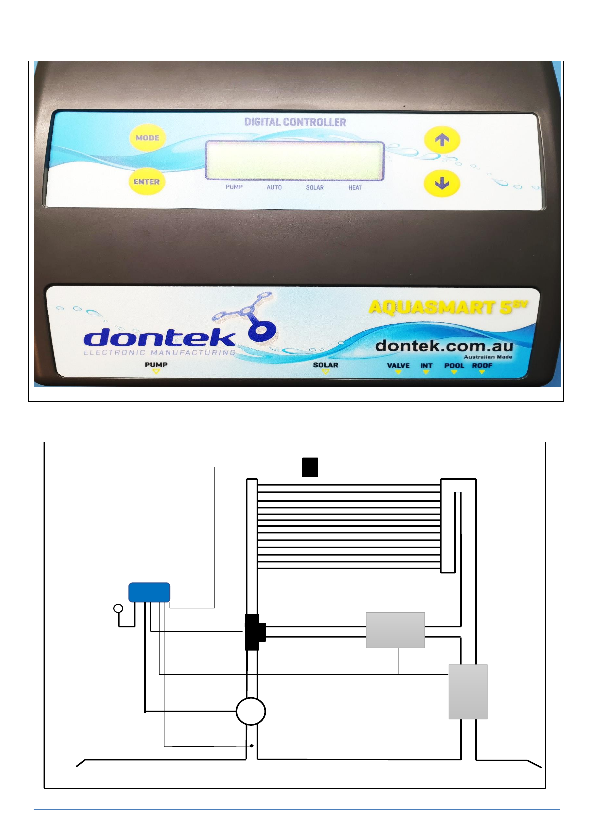
Pressing this button changes to the next mode of operation. Once the mode button is no
longer being pressed then the selected mode of operation is automatically saved.
•Heating mode (Auto) is the normal operating mode for heating the pool.
•Standby mode of operation is for off-season/holiday maintenance or if pool heating is
not required. This is a better option than turning the controller off, as it will flush
treated pool water through the solar system, and prolong solar pump bearing and
mechanical seal life. Pump will run for 3 minutes a day before 1pm.
**Note - Solar and Auxiliary Heating are disabled.
•Night Cool mode is for situations where the pool water overheats beyond the set
temperature limit due to direct heating from the sun. The controller will start the solar
pump when the roof temp drops below the pool temp to cool the pool.
**NOTE - Note for the cooling function to work properly, it is best if the solar run hours have
been left at the factory default (See Installer Setup). This allows the controller to take the
best advantage of evening and early morning hours to cool the pool.
•Filter Manual is for switching the filter pump on or off. This mode can be used for a
3min (Backwash), for running the filter pump for up to 24hrs, or for ensuring that the
filter pump doesn’t turn on for system maintenance.
**NOTE: Once Manual is selected the filter pump will start. Once the pump has started, use
the ↑or the ↓buttons to increase or decrease the length of time that Filter Manual runs. **The
ENTER button will toggle the pump on or off during this mode**. After Manual Mode times-
out, the unit will return to the previous mode, or you can press the Mode button to return to
normal operating Mode.
•Solar Manual is for testing the solar pump installation on a cold or cloudy day. Once
manual mode is selected the pump will start. After manual mode times-out, unit will
return to the previous mode.
•Heat To Limit will ignore the run timer (Heater Cycles) to run the pump until the
desired temperature limit is achieved. Once the temperature limit is reached the
controller revert to Heating mode and run the heating during the set run times.
**The factory default MODE is HEATING MODE
↑AND ↓
BUTTONS
(TEMPERATURE
SETTING)
Adjusting the temperature limit will allow the controller to heat the pool until the temperature
limit +½°C is achieved. Heating will then remain off until the sample wait period expires. If no
sample wait period is active, the heating will remain off until the pool temperature drops ½°C
below the temperature limit setting. Due to rounding the actual heating hysteresis is ±½°C.
***TEMP RANGE: OFF, 20° –40° ***
The ability to solar heat the pool will depend on weather conditions and other factors.
Pressing the ↑Button will display
SOLAR LIMIT
Select this option and the following will display
SET TEMPERATURE;
SOL. LIMIT XX.X° ** The factory default for SOL. LIMIT is 30°C.
Press the ENTER Button to save the temperature, then the following will be displayed
SET TEMPERATURE;
AUX. LIMIT XX.X° ** The factory default for AUX. LIMIT is ON and 27°C.
Press the ENTER Button to save the temperature settings.
Pressing the ↓button will display
HEATER LIMIT
Select this will bypass the setting of the solar limit going straight to AUX. LIMIT.
If the controller is manually put into STANDBY MODE using the Mode button, you will need to reset your AUX
Heating settings to be ON and set the required temperature when the controller put back into HEATING MODE.
This does not apply when using Auto Standby Mode.

AQUASMART 5 SV v1.4
6
ENTER BUTTON
Pressing the ENTER button will turn on the LCD backlight. Pressing the ENTER button while the backlight is lit will
enter the SETTINGS MENU. The following will be displayed:
1) EXIT, the menu system can be navigated using the ↑or ↓buttons. All selectable and changeable values will
flash on the LCD screen. Press the ENTER button to accept the currently displayed (flashing) item.
All menu items are shown below:
1) EXIT
2) HEATER TIMERS
3) SYSTEM
1) EXIT
Will save changes and return to automatic operation.
2) HEATER
TIMERS
HEATER RUN TIMES –When the HEATER RUN TIMES is selected the following is displayed:
No. OF TIMES PER
DAY TO RUN: x
Select the number of times per day you wish the AUX Heating to operate. If OFF is selected
then the pump will only operate for Solar Heating purposes, otherwise the following is
displayed:
One time per day menu:
HEATER CYCLE 1 menu:
HEATER CYCLE
xx:xx TO xx:xx
Twice per day HEATER CYCLE 2 menu:
HEATER CYCLE 1 HEATER CYCLE 2
xx:xx TO xx:xx xx:xx TO xx:xx
Adjust the start time and end time for the required heater cycle(s). The circulation pump will
run between these times for AUX heating purposes.
**Factory Default is ON, ONE TIME PER DAY FROM 06:00 to 22:00.
Note 1: Take care not to overlap heater cycle 2 times with the heater cycle 1 times as the
result will be one cycle per day.
Note 2:For 24hr heating, set the heating to run 1 time per day with the start & end times
the same (E.g. 12:00 –12:00).
Note 3:If the unit is configured to run the heater parallel to the solar, the controller will
not run the heater in conjunction with the solar collectors. It will only run them
individually.
Note 4: When the roof temp probe exceeds the AUX LIMIT + 15oC, there is enough solar
energy to heat the pool. The auxiliary heating is switched off to save energy. The auxiliary
heater remains switched off until the roof temperature drops below AUX LIMIT + 10oC. It
won’t matter if the controller has been configured to run the heater parallel or in-line with
the solar for this to occur.
3) SYSTEM
EXIT - Press ENTER on this menu to return to automatic operation.
SET CLOCK –Allows you to adjust calendar date and time of day.
LCD BACKLIGHT –Adjust the number of seconds the backlight remains on after the time a
button was pressed. (Select NONE for always on.)

AQUASMART 5 SV v1.4
7
INSTALLER SETUP;
TO ACCESS MENU PRESS ENTER AND SCROLL DOWN TO SYSTEM AND PRESS THE MODE BUTTON.
WARNING PROFESSIONAL ONLY SETTINGS!!
FACTORY DEFAULT?
NO/YES
Restore back to factory defaults.
USE
AUTO STANDBY?
YES/NO
When selected you will be prompted to select the start month of Standby and the start
month of Heating.
Standby Mode assists in the solar systems off-season maintenance and saves energy as
solar gain may be available but swimming temperature cannot be achieved, or solar
heating is not desired. A 3min flush of the solar collector occurs between the solar start
time and the end time, providing the roof temperature is equal to or greater than the
pool, but if that condition does not occur before 1pm (13:00) a solar system flush will
be forced to occur.
A start month of ‘always’ can be selected which permanently sets the unit into Standby
mode.
Note: In Auto Standby mode the 2nd filter cycle does not run or the Single Filter Cycle is
halved. Auxiliary Heating parameters are kept.
USE SOLAR DRAIN?
NO/YES
If NO is selected then the solar pump will stop if solar heating is no longer required.
If YES is selected the following menu is presented;
DRAIN IS TO STOP
PUMP FOR?
PUMP FOR xx MINS (RANGE = 03-15 MINUTES)
The controller stops all pumps for the selected number of minutes. This allows for the
water to drain out of the solar collectors before the pool pump is restarted. If the pool
is not at solar limit during the drain process and solar heating becomes available the
system will resume heating.
The system may delay the drain process if the pool is below limit and if the roof
temperature is above the pool temperature.
ALLOW SOLAR
FROM?
xx:xx TO xx:xx
(RANGES = 06:00-12:00 AND 12:00-21:00)
This setting will not allow the solar system to run outside of the times set. (Select 12:00-
12:00 to always allow solar).
USE LIVE SENSOR?
NO/YES
You can option to select a ‘LIVE’ sensor.
Select YES for a commercial system where the pool sensor is in constant water flow.
If you select NO (recommended) to enable the sampling feature. The controller
assumes that pipe temp is not always pool temp.
USE A HEATER?
YES/NO
Selecting NO will disable the AUX heating function, and Heater Run Times will not be
displayed or selectable under 2. TIMERS.
When YES is Selected, the following menu is presented:
SAMPLE TIME:
xx:xx (hh:mm)
The pump stops for the selected time period once the temperature limit is achieved
Heating will then remain off until the sample wait period expires.
If no sample wait period is active the heating will remain off until the pool temperature
drops ½°C below the temperature limit setting. Due to rounding the actual heating
hysteresis is ±½°C.
HEATER TYPE?
GAS HEATER / ELECTRIC HEATER
This setting lets you to select the type of Auxiliary Heater used. Electric heaters/ Heat
pumps require no cool down.
If GAS HEATER is selected the following will be displayed:

AQUASMART 5 SV v1.4
8
HEATER COOL
DOWN?
OFF MINUTE(S)
(RANGE = OFF-20 MINUTES)
Once the heater achieves temperature or if the heating time period ends then the
heater is switched off. The cool down timer ensures that the circulation pump
continues to operate to cool the heater before the pump switches off.
If the ‘use solar valve’ option is selected, a reduced cool-down (1 min) is used before a
valve turn (a full cool-down still occurs before the circulation pump is switched off).
HEATER CONFIG?
INLINE WITH SOLAR/PARALLEL WITH SOL
Heater configuration tells the controller where the heater is located in the return water
path (see diagram on pg4). The normal path is for the solar to return through the heater
back into the pool (heater is located in the return line after the solar collector ‘T’
junction). This is called INLINE WITH SOLAR.
If water from the solar collectors returns to the pool without going through the heater,
select PARALLEL WITH SOLAR.
Note: The heater will not operate in conjunction with solar when the configuration is
set to Parallel.
ROOF
TEMPERATURE?
ROOF TEMPERATURE
START DIFF x.x° (4.0°-40.0°C)
ROOF TEMPERATURE
STOP DIFF x.x° (1.0°-(START -2°C))
ROOF TEMPERATURE
MIN. ROOF xx.x° (OFF,10.0°-60.0°C)
You can modify the differentials. The Start differential is the temperature the roof
needs to rise above the pool to start the pump.
The Stop differential stops the pump when the roof drops below the pool temp plus the
stop differential.
Minimum roof is the roof temperature required for the solar to start heating (Off =
feature disabled).
PRIME PROTECT?
YES/NO
Ensure that the filtration pump is plugged into the outlet labelled as PUMP and the
Sanitiser is plugged into the SANITISER power outlet of the controller.
The controller will ask you if you would like the current detection to be ON or OFF. Use
the ↑or ↓buttons to select the required option and press the Enter button.
If OFF is selected the unit will operate as a standalone solar controller and the PUMP
socket will be powered constantly.
Note: The valve actuator may open in this instance (due to there being solar gain) even
if no water is flowing through the system (ie out of heating time).
If ON is selected then the filtration pump will start.
Ensure the filtration pump is operating (and at the required speed for variable speed
pumps) via the controller’s PUMP socket and is primed, then use the
↑
or
↓
buttons to
select either SET AUTO or SET MAN and press the Enter button.
If you select SET AUTO - the unit will display the pump’s load value for 5 seconds then
automatically sets the threshold levels and returns to automatic operation. If the
current draw of the filtration pump drops below the selected threshold levels then the
solar pump is forced to switch off.
If you select SET MAN. - the unit will display the pump’s load value for 5 seconds, take
note of this value. When the LCD screen displays RUN=>xxx it indicates the minimum
load required to allow solar to run, set this value 15% lower than displayed LOAD value.
Note –SET MAN is usually the best option when setting the pump load settings for a
variable speed pump as the load value can fluctuate more.

AQUASMART 5 SV v1.4
9
FREEZE PROTECT?
NO/YES
(RANGE 1.0°C-6.0°C)
Anti-freeze function, when switched to ON will start the pump when the roof
temperature drops to the selected temperature.
It will operate for 3 minutes every 30 minutes until the roof temperature rises above
the selected temperature.
Default setting is NO.
BOIL PROTECT?
NO/YES
(Range 55oC - 99oC)
(Range 3 - 59mins)
Anti-boil function.
If you select NO, the next option will be offered.
If you select YES, the pump will start when the roof temperature rises to the selected
temperature. It will operate for the selected number of minutes, where the controller
will then take a roof temperature reading and either start the solar pump again (if roof
temp is still above selected temperature) or stop running the pump if the temperature
has dropped below the selected temperature.
Default is NO. If you select Boil Protect to be YES, the controller will display 99oC for
3mins. Adjust to required temperature and time.
PIPE PROTECTION?
NO/YES
Range 50oC - 95oC
For use when solar collectors are flooded, flat and may require a wetted roof sensor for
this mode.
The controller will allow the pool to heat to the selected pool temperature, where it will
then force the controller to stop any further solar heating of the system by not allowing
the solar pump to run once the roof temperature reads above the selected Pipe
Protection setting.
The solar pump will be allowed to run once the roof temp drops below the selected
Pipe Protection temperature.
Default is NO. If you select Pipe Protect to be YES, the controller will display 80oC.
Adjust to required temperature.
Note –Pipe Protection will not be offered if Boil Protection has been turned ON.
CALIBRATE POOL
SENSOR BY:
X.X (RANGE -5.0 TO +5.0°C)
This is for the + series sensor only (TS02P).
NOTES:
1. If any of the menu items are left unattended for 3 minutes the menu will time
out and automatically save all settings and return to automatic operation.
2. If a sensor fault is detected, the controller displays which sensor and what the
fault is.
3. Should power be interrupted for any reason, the controller will resume normal
operation when power is restored. All information will have been kept for up to
10 days.
4. If the controller has stopped the pump and is displaying a higher temperature
than expected it may be caused by a pump which is failing to prime. Check the
pump and if necessary, prime the pump as per the pump manufacturers’
instructions. Then reset the controller by turning it off/on.
5. MAX combined rated output load for the 240V socket(s) is 9.98 Amps / 2395
Watts.
6. Degree of protection against moisture: IP33.
7. Store pool chemicals safely, at least 3 metres away from all pool equipment.

AQUASMART 5 SV v1.4
10
TROUBLE SHOOTING
NO POWER TO THE DISPLAY:
Power point is faulty. Test power point with a known working appliance. If the power point is operational, check the
controller in another power point and if there is still no display then send the controller for repair.
RTC-FAIL –This can occur if the unit has been turned off for a prolonged period of time, leave the unit on for ~30
seconds, then turn it off for ~30 seconds before turning it back on.
PIPE/ROOF SENSOR FAULTS:
The following are error messages caused by pool or roof sensor faults;
SENSOR DISCONNECTED OR OPEN CIRCUIT
Sensor cable unplugged from controller, cable damaged, bad cable join or sensor is damaged.
SENSOR SHORT CIRCUIT OR REVERSED
Sensor cable or cable join polarity is incorrect, or sensor is damaged. The positive side of the cable (grey coloured
wire) should be wired to the righthand side of the plug, with the screws facing towards you and the sensor cable
entry at the bottom of the plug. If the cable has been joined ensure no polarity reversal occurs.
ISOLATING SENSOR FAULTS:
Swap the sensor locations. Put the pipe sensor in the roof socket and the roof sensor in the pipe socket.
If the fault moves from pipe to roof or vice versa then it is likely that there is a sensor fault.
If the fault remains the same then the controller may need to be repaired.
PUMP FAULTS:
Ensure the controller has working sensors; otherwise the pump will not operate.
CIRCULATION PUMP WILL NOT START:
Ensure that the Circulation pump is plugged into the Aquasmart5 SV PUMP power socket properly.
Check the AUX Heating and Solar Heating times set in the Aquasmart5 SV controller, adjust if required.
If it still won’t start plug the filtration pump straight into a power point and turn on. IF the pump doesn’t start then
you have an issue with your pump. If the pump is ok, your controller requires repair.
PUMP WILL NOT STOP:
Turn off power to the controller and ensure the pump stops. If the pump continues to operate then unplug it from
the power point and connect it to the 240Vac socket marked PUMP at the bottom of the controller.
If the pump is plugged into the controller and won’t stop, check to see what is displayed on the controller screen. The
controller may be running for heating purposes.
If the pump is still running, and the controller states that nothing should be running, your controller requires repair.

AQUASMART 5 SV v1.4
11
TROUBLE SHOOTING CONTINUED
POOL NOT HEATING:
If the controller has stopped pumping and is displaying a higher temperature than expected it may be caused by a
pump which is failing to prime. Check the pump and if necessary, prime the pump as per the pump manufacturers’
instructions then reset the controller by turning it off/on.
Check the controller LCD screen to see if any sensor faults are present and fix as required.
Check to see if the error message “Circulation Pump Failed to Prime” appears. If so either reset the Pump Load
Settings (refer to Prime Protection settings in the Installer Setup menu), or disable the Prime Protection feature (refer
to Prime Protection settings in the Installer Setup menu).
If the controller is in Standby Mode, the controller won’t heat the pool using solar heating, no matter what the roof
temperature is. If it is consistently warm enough, switch the controller back into Heating Mode to start heating your
pool.
Check the controller settings to ensure that the AUX temperature and runtime settings are correct.
Check and ensure that the Heater Interlock cable is connected to the plug properly and that the plug is pushed in.
Check and make sure that the heater has power connected.
Check and ensure that the Heater Interlock cable is connected to the appropriate position inside the heater,
according to the heater manufacturer’s instructions.
VALVE ACTUATOR NOT TURNING:
Check and ensure that the wires are screwed into the plug properly and in the correct order (Red, Black, White, from
left to right with the screws of the plug facing upwards towards you).
Check and ensure that the plug is pushed into the Valve socket properly.
Check and ensure that the toggle switch of the actuator is in either of the ON positions and not in the middle OFF
position.
Check the settings of the controller to ensure that the Solar is not turned off, controller is not in ‘Auto Standby
Mode’, and that both sensors are ready.
Make sure that the valve can be turned manually to ensure that the valve isn’t jammed (debris inside the valve, or
valve actuator seized/not working).
If the above all checks out, then you controller needs repair.
FACTORY RESET:
Hold down ENTER when power is off, hold down after powering up, releasing after 5 seconds.
Dontek Electronics Pty Ltd
PO Box 239, Bayswater VIC 3153 Australia
Phone: +613 9762 8800 Email: sales@dontek.com.au

AQUASMART 5 SV v1.4
12
WARRANTY
•This range of product is covered by a limited 3 year warranty against component failure or faulty
workmanship from the date of installation.
•Faulty units should be returned in the first instance to the dealer from which the unit was purchased.
(Return to Base)
•Damage to the unit due to misuse, power surges, corrosion from pool chemical fumes, lightning strikes
and or installation that is not in accordance with the manufacturer’s instruction may void the warranty.
•Warranty does not include on-site labour or travel costs to or from installation site.
•Valves and actuators are covered by a 12 month warranty at the discretion of their manufacturer.
If the power cord is damaged, do not use the controller; return the unit to the supplier for repair.
CUSTOMER RECORD (To be retained by the customer)
DEALER/INSTALLER NAME
SERIAL NUMBER
DATE INSTALLED
For service assistance visit www.dontek.com.au
Dontek Electronics Pty Ltd
PO Box 239, Bayswater VIC 3153 Australia
Phone: +613 9762 8800 Email: sales@dontek.com.au
Table of contents
Other Dontek Controllers manuals

Dontek
Dontek AQUATEK User manual

Dontek
Dontek V2-1 User manual

Dontek
Dontek Aquasun 3CD User manual

Dontek
Dontek H7 SV User manual

Dontek
Dontek Aquasun 3 User manual

Dontek
Dontek H3BR User manual

Dontek
Dontek V7-RTS User manual

Dontek
Dontek Aquasun 3 FRP User manual

Dontek
Dontek AquaSun 3RB User manual

Dontek
Dontek V2 Series Service manual
Popular Controllers manuals by other brands

ABB
ABB TCC300 quick start guide

Promation Engineering
Promation Engineering P2-120PN4-HR Installation & operation manual

Baker Hughes
Baker Hughes Mooney Flowgrid instruction manual

Fisher
Fisher 3570 instruction manual

Philips
Philips Dynalite DMAL120F installation instructions

SMC Networks
SMC Networks CRB10 Operation manual