Warning this manual contains the exclusive instructions for use for professionally qualied
installers and/or maintenance technicians, in compliance with laws in force.
e individual in charge of the system is NOT authorised to work on the boiler.
e manufacturer will not be held liable in the case of damage to people, animals or property
due to the failure to observe the instructions contained in the manuals supplied with the boiler.
1 General information...................................................................4
1.1 Symbols used in the manual........................................................4
1.2 Compliant use of the appliance...................................................4
1.3 Information to be provided to the user .....................................4
1.4 Safety warnings .............................................................................5
1.5 Regulations for installation..........................................................6
1.6 Installation.....................................................................................6
1.7 Water treatment ............................................................................7
1.8 general warnings...........................................................................8
2 Technical characteristics and dimensions.................................9
2.1 Technical characteristics..............................................................9
2.2 View of main parts......................................................................10
2.3 Dimensions..................................................................................11
2.4 Operating data / general characteristics ..................................12
3 Instructions for installation.....................................................13
3.1 General recommendations........................................................13
3.2 Packaging.....................................................................................14
3.3 Operation to unload and remove the packaging ...................15
3.4 Positioning the heating control unit.........................................16
3.5 Connecting the boiler ................................................................17
3.6 Gas connection............................................................................18
3.7 System ow and return pipe connection.................................19
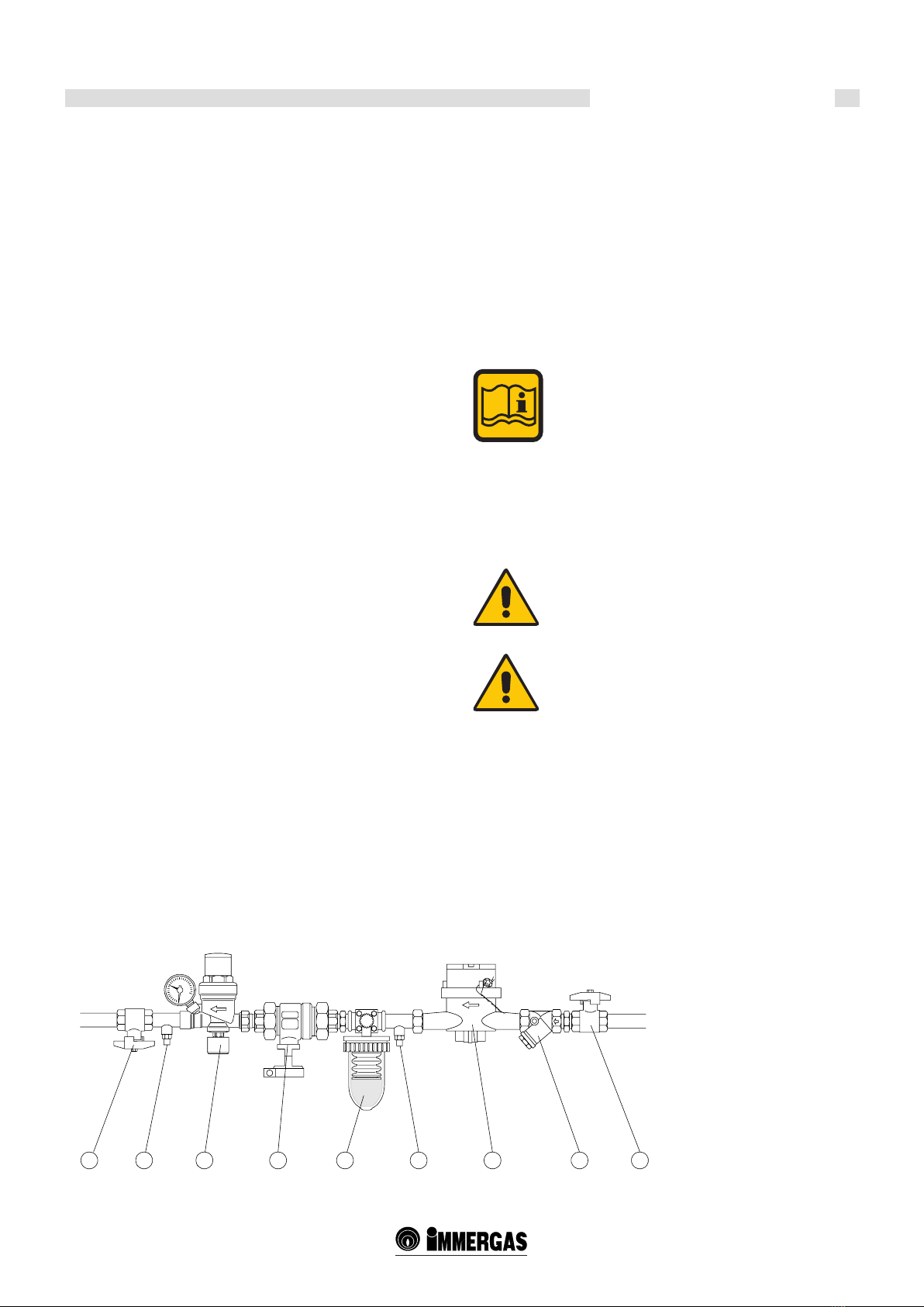
3.8 Additional safety, protection and control devices ..................20
3.9 Hydraulic separator....................................................................21
3.10 Hydraulic system lter ...............................................................21
3.11 Determining the primary circuit pump or boiler pump .......22
3.12 Ball valves.....................................................................................22
3.13 complete optional kits................................................................23
3.14 condensate drain.........................................................................24
3.15 Connecting the ue ....................................................................25
3.16 Flue exhaust manifold connection ...........................................25
3.17 Electrical connections................................................................27
General recommendations........................................................27
230V electrical supply connection ...........................................28
3.18 Connection diagram ..................................................................29
Power supply, gas electrovalve, INAIL, ON/OFF
pump, external probe, ow switch............................................29
Power supply, gas electrovalve, INAIL, modulating pump,
external probe, ow switch........................................................29
INAIL safety connection
(supplied with modulating pump). ..........................................30
ON/OFF thermostat connection..............................................30
Modulating room thermostats connection.............................31
Modulating zone manager connection....................................31
3.19 Practical connection diagram ...................................................32
3.20 Connections and management diagram..................................34
3.21 Examples of installation (functional diagram and
description of connections).......................................................36
3.22 System lling and emptying......................................................41
3.23 Boiler frost protection................................................................41
3.24 Check the adjustment of the pressure to the burner..............42
Nozzles - pressures. ....................................................................44
3.25 Emergency and safety operations ............................................46
3.26 First ignition................................................................................47
4 Inspections and maintenance ..................................................48
INDEX
Immergas S.p.A. declines all liability due to printing or transcription errors, reserving the right to make any modications to its technical and
commercial documents without prior notice.
Mauro Guareschi
Research & Development Director
Signature:
CE DECLARATION OF CONFORMITY
(according to ISO/IEC 17050-1)
e company IMMERGAS S.p.A., with registered oce in via Cisa Ligure 95 42041 Brescello (RE) whose design, manufacturing, and aer sale
assistance processes comply with the requirements of standard UNI EN ISO 9001:2008,
DECLARES that:
e ARES 440 TEC ERP, ARES 550 TEC ERP, ARES 660 TEC ERP, ARES 770 TEC ERP, ARES 900 TEC ERP model boilers comply with the
following European Directives and Delegated European Regulations:
“Eco-design” Directive 2009/125/EC, “Energy labelling” Directive 2010/30/EC, “Gas Appliance” Directive 2009/142/EC, “Electromagnetic Com-
patibility” Directive 2004/108/EC, “Performance” Directive 92/42/EC and “Low Voltage” Directive 2006/95/EC.