manuals.online logo
Brands
  1. Home
  2. •
  3. Brands
  4. •
  5. Immergas
  6. •
  7. Boiler
  8. •
  9. Immergas NIKE Star 23 kW User manual

Immergas NIKE Star 23 kW User manual

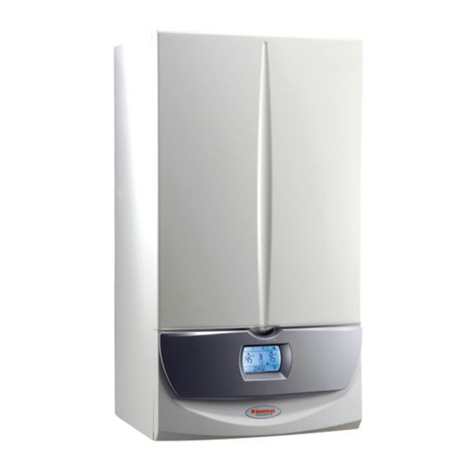
NIKE Star 23 kW
Instantaneous wall-hung
with open chamber boilers
NIKE Star 23 kW
1
STNSkW ed 05/06 NIKE Star 23 kW
Technical Documentation Technical Documentation
NIKE Star 23 kW
Compact instantaneous wall-hung
conventional flue boiler.
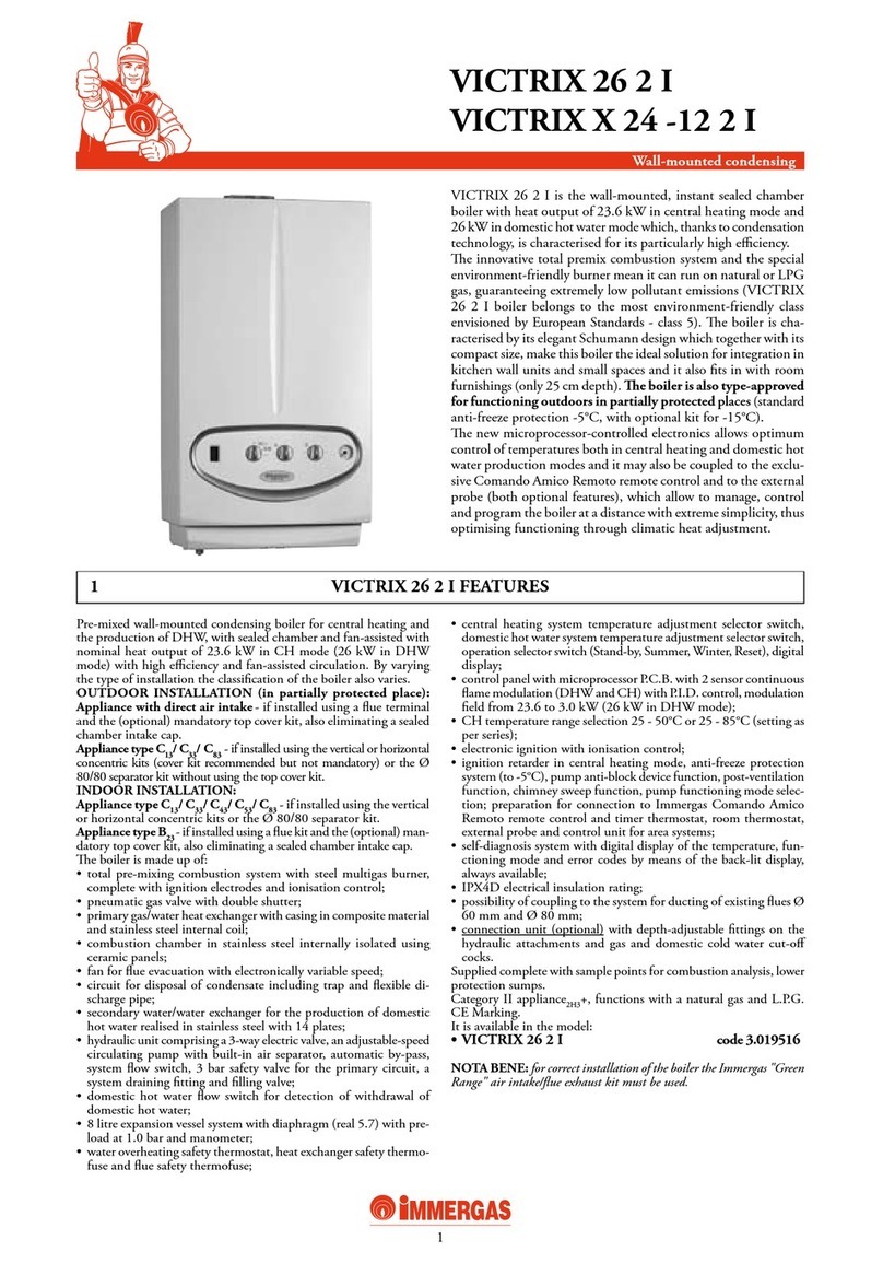
NIKE Star 23 kW
NIKE Star 23 kW is a wall-hung conventional flue boiler for
heating and production domestic hot water.
It is distinguished by its compact size (H=780 mm, W=450
mm, D=250 mm), has an heat output of 23.3 kW (20,000
kcal/h).
A microprocessor controlled electronic board adjusts and
controls the appliance (burner ignition, temperature adjustment,
flame modulation and diagnostics) and the operating parameters
can be displayed and set by means of a digital interface with
display and push buttons.
General features.
e hydraulic circuit is equipped with a copper bithermal type
water-gas exchanger for the production of hot water for central
heating and domestic use, an automatic by-pass on the system
and a flow switch for tapping the domestic hot water.
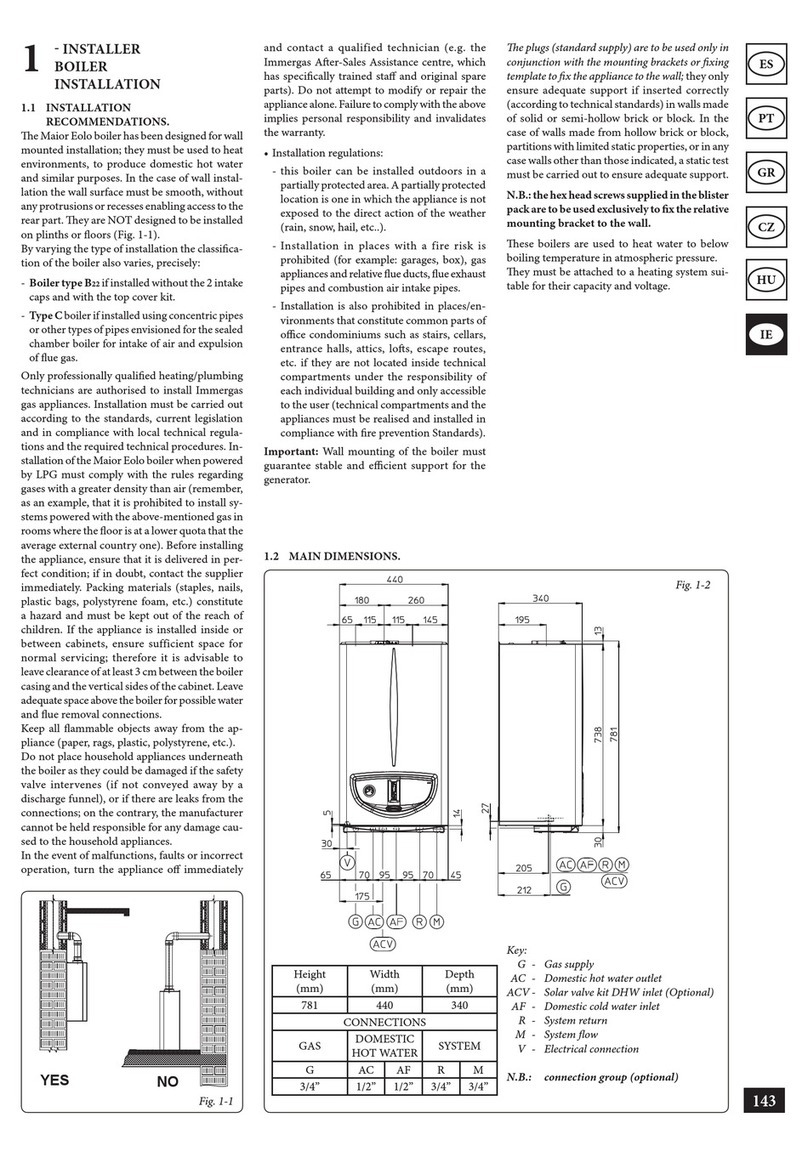
Legend:
G - Gas supply
AC - Hot water outlet
AF - Cold water inlet
R - System return
M - System delivery
V - Electrical supply
Main dimensions and main connections.
Height (mm) Width (mm) Depth (mm)
780 450 250
Connections
GAS DOMESTIC
WATER SYSTEM
G AC AF R M
3/4” 1/2” 1/2” 3/4” 3/4”
2
STNSkW ed 05/06 NIKE Star 23 kW
Technical DocumentationTechnical Documentation
Legend:
1 - Filling valve
2 - Boiler pressure gauge
3 - D.h.w. probe
4 - Gas valve
5 - D.h.w. flow switch
6 - Combustion chamber
7 - Draught diverter
8 - Flue safety thermostat
9 - Delivery probe
10 - Safety thermostat
Main components.
11 - System expansion vessel
12 - Automatic air vent
13 - Boiler circulator
14 - System pressure switch
15 - Manifold
16 - 3-bar safety valve
17 - Draining cock
18 - Rapid heat exchanger
19 - Ignition and detection electrodes
20 - Burner
3
STNSkW ed 05/06 NIKE Star 23 kW
Technical Documentation Technical Documentation
Legend:
1 - Reset Push Button
2 - Stand-by / Summer / Winter Push Button
3 - Push button (+) to increase d.h.w. temperature
4 - Push button (-) to reduce d.h.w. temperature
5 - Push button (+) to increase system water temperature
6 - Push button (-) to reduce system water temperature
7 - Boiler pressure gauge
8 - D.h.w. functioning mode
Control panel.
9 - Displays temperatures and error codes
10 - Unit of measure
11 - Central heating functioning mode
12 - Winter
13 - Summer
14 - Power supplied
15 - Burner operating
4
STNSkW ed 05/06 NIKE Star 23 kW
Technical DocumentationTechnical Documentation
e central heating circuit, with relevant control and safety
devices, is operated every time a central heating request is
made.
Operation.
e heat contained in the fumes produced by combustion
is absorbed by the copper blades of the water-gas exchanger
(7) which, in turn, transfers it to the water circulating inside
thanks to the boiler circulator (14).
e hot water is then transferred directly into the central heat-
ing system through the delivery (M) and return (R) pipes.
Legend:
1 - D.h.w. probe
2 - D.h.w. flow switch
3 - Gas valve
4 - Flow limiter
5 - Draining cock
6 - Burner
7 - Rapid heat exchanger
8 - Draught diverter
9 - Flue safety thermostat
10 - System expansion vessel
11 - Delivery probe
12 - Safety thermostat
13 - Automatic air vent
14 - Boiler circulator
15 - System pressure switch
16 - Automatic by-pass
17 - 3-bar safety valve
18 - Filling valve
G - Gas supply
AC - D.h.w. outlet
AF - Cold water inlet
R - System return
M - System delivery
Hydraulic circuit.
Primary circuit (Boiler Circuit).
Hot water for central heating and domestic use is produced
by two separate circuits that work as required.
5
STNSkW ed 05/06 NIKE Star 23 kW
Technical Documentation Technical Documentation
Boiler circulator (1).
e pump works on the primary circuit return and is located
on the brass manifold assembly.
It is connected to the enbloc and primary exchanger by means
of threaded fittings.
e automatic valve vent is housed on the body (2).
Primary exchanger.
is is a water-gas bithermal type blade exchanger with pipes
and fins in copper for the production of hot water for central
heating and domestic use.
It therefore works directly on both circuits to which it is con-
nected by pipes with threaded fittings (3) with a flat gasket
seal (4).
e 6 oval pipes it consists of, inside which flows the water of
the central heating circuit, contain an equal number of “cross-
shaped” pipes for the direct transit of domestic hot water (see
illustration below).
ese pipes are plumbed in parallel in groups of three on the
central heating circuit and in series on the d.h.w. circuit.
e overheating safety thermostat (2) is fixed on the side of
the exchanger exit with a fork (1).
e relevant NTC delivery probe is screwed into place on the
central heating delivery pipe (5).
Head flow rate graph.
e available head the appliance is able to guarantee to the
system in the central heating mode depends on the flow rate
which is shown in the following graph where we can see the
characteristic curve with the pump working at second and
top speed.
Head (m H2O)
A = Head available to the system at third speed
B = Head available to the system at second speed
Head (kPa)
A
2
1
Domestic
cold
water
inlet Domestic
hot
water
outlet
Domestic
hot
water
outlet System
delivery
System
return
Exchanger pipe section
System
central
heating circuit
D.h.w.
circuit
B
Flow rate (l/h)
6
STNSkW ed 05/06 NIKE Star 23 kW
Technical DocumentationTechnical Documentation
Safety devices and controls.
Automatic system by-pass (4).
is device ensures circulation in the central heating circuit
even when this is prevented by the system’s high resistance.
It works between the delivery and return of the central heating
circuit and is accessible after having unscrewed the cap (5) on
the brass manifold’s hook (1).
System water pressure switch (7).
is is an absolute pressure switch that reads the pressure inside
the central heating circuit.
It is housed in the manifold (1) and coupled to a microswitch
that prevents the boiler working when the pressure measured
is below 0.3 bar.
is prevents the bithermal exchanger from overheating.
Filling valve (3).
is valve is between the boiler circuit and the domestic cold
water inlet and permits pressurisation of the central heating
system.
It is located underneath the brass manifold (1) to which it is
screwed.
3-bar safety valve (2).
is valve prevents the safety pressure being exceeded in the
circuit (3 bar).
It is on the front of the manifold (1), secured to it on the side
with an Allen screw.
When this valve triggers, water exits from the boiler return
pipe.
Automatic air vent (8).
It automatically expels any gaseous substances from the cir-
cuit.
It is mounted on the pump’s delivery side.
Expansion vessel (9).
It compensates for variations in volume as a result of heating
the water which also limits pressure variations.
It has a 6-litre capacity (4.0 useful litres) and a pre-load pres-
sure of 1.0 bar.
It is located on the right of the boiler alongside the sealed
chamber and is connected to the return manifold (1) by a
copper pipe (6) with threaded fittings.
8
9
6
7
4
5
1
2
3
6
Central
heating
exchanger
delivery
Pump
return
System
delivery
System
return
7
STNSkW ed 05/06 NIKE Star 23 kW
Technical Documentation Technical Documentation
Secondary circuit (D.h.w. circuit).
Operation.
When domestic hot water is drawn, cold water flows inside
the flow switch (4) which closes the electrical contact coupled
to it (see the electrical circuit).
As a result, the adjustment circuit starts the d.h.w. priority
phase that ignites the burner (3) and, if there is an ongoing
central heating request, switches the boiler circulator off.
In this way, the heat in the fumes produced by combustion is
absorbed by the copper blades of the bithermal exchanger (2)
and transferred to the heating circuit water which, in turn,
transfers it to the domestic water circuit flowing through the
“cross-shaped” hot water circuit pipes (1).
D.h.w. flow switch.
Whenever hot water is drawn at a rate of at least 2.5 l/min and
with a dynamic pressure of 0.3 bar, the flow switch (2) enables
the boiler to operate in the d.h.w. mode.
is is done by means of a magnet that, by lifting when hit by
the flow of cold water, moves near to an electrical contact (reed
relay) causing it to move thanks to the effect of the magnet.
When the contact closes, which is located outside the pipe
through which the water flows, it enables the modulation board
to start the domestic hot water priority operating mode.
It consists of two blocks (one in brass and one in plastic) that
are coupled together and locked with a pin (3).
An 8.0 l/min (2 bar) flow limiter (1) is installed at the flow
switch exit.
Bithermal exchanger
(see the central heating circuit).
Note: to ensure long life and have an exchanger that is always
efficient, we recommend installing the “polyphosphates dispenser
kit” if the water is likely to lead to scale forming. For example,
this kit is recommended when the hardness of the water exceeds
25 French degrees.
1
2
3
Cold domestic
water inlet
8
STNSkW ed 05/06 NIKE Star 23 kW
Technical DocumentationTechnical Documentation
e circuit consists of an atmospheric burner and a modu-
lating gas valve for gas combustion and flow adjustment
respectively.
Operation.
When the main coils are energised (3) both the inner valve
shutters open allowing gas to flow towards the burner.
e flow rate/outlet pressure is set by means of the gas valve
stabiliser and the modulation coil (1).
By mean of the burner nozzles (7) fuel is injected into the Ven-
turi tubes (ramps) inside which the air-gas mixture is obtained
that is ignited by the spark from the ignition electrode (5).
Modulating gas valve.
e gas valve (SIT 845) features two main coils (3) and a
modulation coil (1) controlled by the integrated board.
e maximum and minimum outlet pressure can be set with
this valve (see gas settings).
Main electric coils (3).
ey are two ON-OFF type coils supplied (230 Vac) by the
integrated board when the burner has to be ignited.
ey are electrically connected in parallel and supplied by
mains power through a special connector (2).
Modulation coil (1).
is is a low voltage coil controlled by the integrated board.
It controls the gas valve stabiliser and permits changing of
the outlet pressure in a way proportionate to the DC running
through it.
Gas circuit.
Burner.
e burner consists of 12 horizontal Venturi tubes (6) inside
which the gas is injected by an equal number of nozzles (7)
mounted on the specific manifold (8) and whose diameter
varies according to the type of gas used (see technical data).
Ignition occurs by means of an integrated p.c.b. that controls
the ignition (5) and detection (4) electrodes.
Ignition electrode (5).
is is controlled by the integrated board that produces an
electrical charge between its end and the burner surface which
is responsible for igniting the air-gas mix.
is electrode is at the front of the burner in line with the
centre ramp.
Detection electrode (4).
is is controlled by the integrated board and detects burner
ignition.
It is positioned at the front of the burner on the same ramp
as the ignition electrode.
1
3
2
9
STNSkW ed 05/06 NIKE Star 23 kW
Technical Documentation Technical Documentation
Gas settings.
Maximum and minimum gas pressure settings are done by
means of the gas valve, respecting the values shown in the
tables relating to each appliance for the relevant type of gas
(see technical data).
e features of this appliance are such as to make it possible to
differ minimum pressure settings during operation in both
the central heating and domestic hot water modes.
e minimum gas pressure setting on the gas valve does in
fact correspond to the minimum pressure in the d.h.w.
phase (7.0 kW = 6,000 kcal/h) while, with regard to heat-
ing, the minimum pressure (9.3 kW = 8,000 kcal/h) can
Legend:
1 - Coil
2 - Minimum power adjustment screw
3 - Maximum power adjustment nut
4 - Gas valve outlet pressure point
5 - Gas valve inlet pressure point
6 - Protection cap
SIT 845 valve
be adjusted by means of the “Minimum central heating
power” parameter programmable on the integrated p.c.b.
(see integrated board programming).
A differential pressure gauge is used for reading the pressure,
whose positive pressure point is connected to the gas valve (4)
outlet (see figure).
Gas valve SIT 845.
Setting maximum pressure.
Draw some domestic hot water after having put its temperature
selector on maximum.
Turn the brass nut (3) clockwise to increase pressure to the
burner and in the opposite direction to reduce it.
Setting minimum pressure
(to be done after setting maximum pressure).
After turning power off to the modulation coil, turn the screw
(2) clockwise to increase pressure to the burner and in the op-
posite direction to reduce it.
Converting gas type.
Adaptation to a type of gas different to the standard one the
boilers are intended for can be done by using the special kits
(natural gas or LPG).
Conversion consists in replacing the burner nozzles and
modifying the “P1” parameter programmable on the integrated
p.c.b. (see integrated board programming).
Maximum and minimum d.h.w. pressures are then set on the
gas valve in the way described above.
Maximum and minimum power in the central heating mode
can be set by means of parameters (see integrated board opera-
tion).
Burner ignition pressure is not set because the type of board
operation does not require this type of setting (see integrated
board operation).
10
STNSkW ed 05/06 NIKE Star 23 kW
Technical DocumentationTechnical Documentation
e electrical circuit of the NIKE Star 23 kW boiler is man-
aged 100% by a microprocessor driven p.c.b. which controls
the boiler’s functions.
Some of the control and safety devices operate at mains voltage
(230 Vac) while others at low voltage.
Electrical circuit.
230 V AC circuit.
Safety devices and controls.
It detects burner ignition, being hit by its flame.
It’s connected to the integrated board.
Detection electrode
(E2)
ey interrupt power to the circuit when power input is higher
than 3.15 A.
ey are mounted on the integrated board.
Line fuse (F1)
Neutral fuse (F2)
Fuse
3.15 AF 250 V
Legend:
B1 - Delivery probe
B2 - D.h.w. probe
CRD - Remote Digital Control (optional)
DS1 - Display
E1 - Ignition electrode
E2 - Detection electrode
E4 - Safety thermostat
E6 - Flue safety thermostat
F1 - Line fuse
F2 - Neutral fuse
M1 - Boiler circulator
S2 - Functioning button
S3 - Block reset push button
S4 - D.h.w. flow switch
S5 - System pressure switch
S20 - Room thermostat (optional)
S21 - D.h.w. temperature increase push
button
S22 - D.h.w. temperature decrease push
button
S23 - Central heating temperature
increase push button
S24 - Central heating temperature
decrease push button
T1 - Ignition transformer
T2 - Boiler board transformer
X40 - Room thermostat jumper
Y1 - Gas valve
Y2 - Gas valve modulation coil









11
STNSkW ed 05/06 NIKE Star 23 kW
Technical Documentation Technical Documentation
Loads.
It is powered by the integrated board when there’s either a central heating or antifreeze
request.
It permits circulation in the primary circuit.
Boiler circulator
(M1)
It is powered at mains voltage by the integrated board when it is necessary to ignite the
burner.
It permits the flow of gas to the burner.
Gas valve (Y1)
(main coils)
It is controlled by the integrated board that provokes a spark between its end and the
burner surface that ignites the air/gas mix.
Ignition electrode
(E1)
Low voltage circuit.
is switch acts on the integrated board after some domestic water
has been drawn, causing the boiler to work in the d.h.w. mode.
When idle it enables operation in the central heating mode.
D.h.w. flow switch
(S4)
Interrupted
contact
Safety devices and controls.
When pressure in the boiler circuit is below 0.3 bar the burner
switches off.
System pressure switch
(S5)
Interrupted
contact
is board is always powered regardless of the position of the functioning button (S2)
(see integrated board operation).
Integrated board
is device is to control the appliance remotely (SUMMER / WIN-
TER selection, setting and indicating temperatures, displaying alarms,
resetting, etc.) and acts as a weekly timer/room thermostat.
If the CRD is installed the X40 jumper must be removed.
Remote Digital Control
(CRD)
(optional)
See Remote
Digital Control
Operation
(CRD)
It unblocks the boiler following either the ignition failure or over-
temperature safety device triggering; it can be used to activate the
chimney sweep function.
If pressed together with the functioning button (S2) it lets you
access the boiler parameter settings.
Reset push button
(S3) Push button
12
STNSkW ed 05/06 NIKE Star 23 kW
Technical DocumentationTechnical Documentation
e burner switches off when the safety temperature is exceeded
(105 °C).
It is located at the main exchanger outlet.
Safety thermostat
(E4)
Clicson thermo-
stat with normally
closed contact
It is powered by the integrated board with a variable continuous current.
It permits varying of the gas pressure to the burner.
Gas valve modulation coil
(Y2)
Loads.
If stack draught is poor it acts on the integrated board stopping
the boiler for 30 minutes.
It is positioned on the right of the draught diverter.
Flue safety thermostat
(E6)
Clicson thermo-
stat with normally
closed contact
e possible functioning selections are:
= Circuit powered, the antifreeze and antiblock functions
are still active, the post circulation function is completed.
( ) = Boiler operation in SUMMER.
( ) = Boiler operation in WINTER.
Functioning button
(S2) Push button
It enables operation in the central heating mode when room tem-
perature is below that required.
If this room thermostat is installed the X40 jumper must be re-
moved.
Room thermostat (S20)
(external optional)
Interrupted
contact
It lets the integrated board measure the temperature of the delivery
water in the primary circuit.
If it breaks the burner stops working whether in the central heating
or d.h.w. mode.
It is located on the central heating delivery pipe of the bithermal
exchanger.
Delivery probe
(B1)
NTC probe
10 kohm 25°C
It lets the integrated board measure the outlet temperature of the
domestic hot water.
If it breaks, functioning in the d.h.w. mode is stopped but function-
ing in the central heating mode is allowed.
It is inserted in the d.h.w outlet pipe connected to the bithermal
exchanger.
D.h.w. probe
(B2)
NTC probe
10 kohm 25°C
13
STNSkW ed 05/06 NIKE Star 23 kW
Technical Documentation Technical Documentation
Electrical circuit.
Central heating phase.
Working with the room thermostat.
By selecting the (Winter) functioning mode with the (S2)
push button the boiler is enabled to work in the central heat-
ing mode.
When the room thermostat (S20) closes the integrated board
powers the boiler circulator (M1) by means of relay K3.
If the following conditions occur: the system pressure switch
contact (S5) is closed (pressure in the primary circuit higher
than the minimum value), the safety thermostat (E4) and the
flue safety thermostat (E6) are enabled, and the temperature
read by the NTC delivery probe (B1) is below the value set
on the boiler’s control panel, then the P.C.B. energises the
request relay K2.
is operation causes the closing of the 2 contacts which starts
the ignition cycle, first of all supplying the ignition electrode
(E1) and then both the coils of the gas valve (Y1).
Burner ignition is detected by the integrated board by means
of the ionisation electrode (E2).
Remote digital control operation.
By selecting the Winter functioning mode on the Remote
Digital Control (CRD) panel, the boiler is enabled to work
in the central heating mode.
If the conditions detected by the CRD require ignition in the
central heating mode, the integrated board powers the boiler
circulator (M1) via the relay K3 and the burner ignites as
described above.
Note: With each switching off when the temperature is
reached, the integrated board stops the burner working in
the central heating mode for a time equal to that set with the
board parameters (see integrated board operation).






14
STNSkW ed 05/06 NIKE Star 23 kW
Technical DocumentationTechnical Documentation
Electrical circuit.
D.h.w. phase.
Operation.
By selecting the (Summer) or (Winter) functioning
mode with the (S2) push button the boiler is enabled to work
in the domestic hot water mode.
When domestic water is drawn it causes the d.h.w. flow
switch (S4) contact to close and enables operation in the
d.h.w. mode.
e boiler circulator (M1) is not started in the domestic
hot water mode or it is switched off if there is an ongoing
central heating request subsequent to relay K3 opening.
If the temperature read by the NTC d.h.w. probe (B2) is below
the value set on the boiler’s control panel (or on the CRD if
installed) boiler ignition is requested.
If the contact of the system pressure switch (S5) is closed
(pressure in the primary circuit higher than the minimum value)
the board, being enabled by the safety thermostat (E4) and
by the flue safety thermostat (E6), closes the contact of relay
K4 and of the request relay K2 causing the 2 contacts to close
and the ignition cycle to start, first of all triggering the ignition
electrode (E1) and then both the coils of the gas valve (Y1).
Burner ignition is detected by the integrated board by means
of the ionisation electrode (E2).






15
STNSkW ed 05/06 NIKE Star 23 kW
Technical Documentation Technical Documentation
Modulation board.
Inside the boiler’s control panel is a microprocessor controlled
electronic board that controls the appliance’s electrical devices
and sees to the linear modulation of burner power.
e appliance’s functioning status is shown on a display indi-
cating if any of its safety devices have triggered.
e same board is used on all models, whether they are the
conventional or sealed chamber types (NIKE/EOLO Star
kW). e different boiler functioning modes are recognised
automatically by means of the appliance’s wiring.
e integrated board is always powered regardless of the operat-
ing position determined by the functioning button (S2).
e board executes a periodical self-check to make sure it is
working properly. During the central heating functioning
mode or with the boiler in Stand-by, this function is activated
every 18 hours from the last boiler check/powering. During
the d.h.w. functioning mode, this self-check starts within
10 minutes from the last time water was drawn and lasts 10
seconds.
NOTE: the boiler stops working (together with indications)
during the self-check operation.
Operation.
Central heating request.
By selecting the (Winter) functioning mode with the (S2)
push button the boiler is enabled to work in the central heat-
ing mode.
When the room thermostat (S20) closes the integrated board
powers the boiler circulator (M1) by means of relay K3.
If the following conditions occur: the system pressure switch
contact (S5) is closed (pressure in the primary circuit higher
than the minimum value), the safety thermostat (E4) and the
flue safety thermostat (E6) are enabled, and the temperature
read by the NTC delivery probe (B1) is below the value set
on the boiler’s control panel, then the P.C.B. energises the
request relay K2 causing the 2 contacts to close which starts
the ignition cycle.
During the first few seconds after the gas valve (Y1) has been
powered, the current to the modulation coil (Y2) is limited to
the predefined soft ignition current.
e burner will then go to the minimum set value (set in the
“Minimum Central Heating Power*” parameter), reaching the
maximum set value (if requested) (set in the “Maximum Cen-
tral Heating Power*” parameter) in a time set in the “Central
Heating Ramp Time*” parameter.
Subsequently, the signal is varied directly proportionate to the
difference between the temperature set on the boiler control
panel and the temperature read by the delivery probe (B1).
When the set temperature (+5°C) is exceeded, the K2 relay
contact opens and the burner is switched off. Re-ignition
time depends on how the “Central Heating Ignitions Timer”
parameter is set.
Each time the burner switches off the fan and pump keep
working for another 30 seconds.
* see Integrated board programming.
    






16
STNSkW ed 05/06 NIKE Star 23 kW
Technical DocumentationTechnical Documentation
D.h.w. request.
When domestic water is drawn it causes the d.h.w. flow switch
(S4) contact to close and enables operation in the domestic
hot water mode.
When the boiler is working in the d.h.w. mode the boiler
circulator (M1) is not started or it is switched off if there
is an ongoing central heating request subsequent to open-
ing of relay K3.
For burner ignition proceed in exactly the same way as for the
central heating mode.
During the first few seconds after the gas valve (Y1) has been
powered, the current to the modulation coil (Y2) is limited to
the predefined soft ignition current.
Once the flame is detected, the signal to the modulation coil
is increased so as to immediately reach the maximum power
set on the gas valve (if requested).
Flame modulation then occurs with reference to the difference
between the temperature set on the boiler control panel and
the temperature measured by the d.h.w. probe (B2).
When the temperature of 65°C is exceeded, the K2 relay
contact opens and recloses as soon as the temperature drops
below 64 °C.
An increase in delivery temperature that goes beyond the trig-
gering limit point (80°C) causes a proportional reduction in the
modulation current in order to limit such a temperature.
Central heating antifreeze request.
When the temperature measured by the central heating delivery
probe (B1) drops below 4°C, the board enables ignition and
keeps the boiler going with the burner at minimum power until
a boiler temperature of 42°C is reached (radiator antifreeze).
Domestic hot water antifreeze request.
If the temperature measured by the d.h.w. probe (B2) drops
below 8°C, the integrated board enables ignition of the boiler
circulator.
If, on the other hand, the temperature measured by the d.h.w.
probe (B2) drops below 4°C, the board enables boiler ignition
and keeps it going with the burner at minimum central heat-
ing power until the d.h.w. probe (B2) measures a temperature
of 8°C after which a post circulation cycle is activated in the
central heating mode that lasts 150 seconds.
e water in the primary circuit is kept below 42°C during
operation because if this temperature is reached the board
switches the burner off.
“Chimneysweep” request.
Pressing the “Reset” push button (S3) for at least 10 seconds
and releasing it, the board enables ignition of the boiler and
keeps it working at maximum central heating power set for
15 minutes.
During this time only the limit thermostat function is observed
(90°C) which is carried out by means of the central heating
delivery probe (B1).
e function is indicated on the boiler display, with the (
and ) symbols flashing; it cannot work if there is an ongo-
ing d.h.w. request.
It can be interrupted by cutting power to the circuit, putting
the boiling in Stand-by ( ), either carrying out a d.h.w.
request or after 15 minutes.
17
STNSkW ed 05/06 NIKE Star 23 kW
Technical Documentation Technical Documentation
Inputs.
When the pressure in the primary circuit is below 0.3 bar this
switch cuts power off to the K2 relay preventing the start of the
ignition cycle.
System pressure switch
(S5)
Open =
no pressure
Closed =
pressure OK
is signal indicates the burner flame has been detected.
It allows the board to increase current to the modulation coil (Y2) after having limited it
during the ignition phase.
It keeps the gas valve (Y1) open.
Flame detection
(E2)
It indicates an ongoing d.h.w. request.
After domestic hot water has been drawn, it enables boiler opera-
tion in the domestic hot water mode which is given priority over
the system central heating mode.
D.h.w. flow switch
(S4)
Closed = d.h.w.
request
It is a resistor that varies in an inversely proportionate way to the
temperature of the primary circuit delivery water.
It is also used as a limit thermostat (90°C).
Delivery probe
(B1)
NTC probe
10 kohm 25 °C
It is a resistor that varies in an inversely proportionate way to the
domestic hot water outlet temperature.
D.h.w. probe
(B2)
NTC probe
10 kohm 25 °C
It is a switch with free contacts that sends a (low voltage) signal to
the board, enabling operation in the central heating mode when
room temperature is below that requested.
Room thermostat
(S20)
(external optional)
Open = Central
heating OFF
Closed = Central
heating ON
It sends to the electronic board the signals about the functioning mode (Stand-by / Summer
/ Winter), the temperatures setting (domestic hot water and central heating) and the heating
requests (times, room temperature, etc.).
Remote Digital Control
(CRD)
(optional)
It enables burner ignition by energising relay K2 when the fumes
are expelled correctly.
If stack draught is poor it acts on the integrated board stopping
the boiler for 30 minutes.
Flue safety thermostat
(E6)
Closed = request
ON
Open = request
OFF
18
STNSkW ed 05/06 NIKE Star 23 kW
Technical DocumentationTechnical Documentation
Outputs.
It is a unipolar relay for controlling the pump (M1) that is excited when its operation is
requested.
Pump relay
(K3)
is is a bipolar relay that is excited when the burner has to be ignited.
By means of its contact, boiler ignition is enabled.
Request relay
(K2)
It is a d.c. signal that controls the modulation coil; the pressure of gas to the burner may
be varied according to the output required.
Gas valve modulation coil
(Y2)
is is a (BUS) signal by means of which boiler temperature, operation in the d.h.w.
or central heating mode, and triggered alarms codes can be seen on the remote control
display.
Remote Digital Control
(CRD)
(optional)
It is a 230 V ac signal indicating that the main gas valve (Y1) coils
are supplied.
Gas valve power supply
(Y1)
230 Vac = coils
supplied
0 Vac = coils not
supplied
It is a high voltage signal (higher than 16 kV) that determines an electrical discharge at the
end of the ignition electrode located on the burner.
Ignition electrode
(E1)
It is a unipolar relay that is excited simultaneously with request relay K2 when its opera-
tion is requested.
Relay (K4)
e boiler circulator (M1) is turned on for 30 seconds after:
- 24 hours of inactivity with the boiler in the SUMMER mode ( ).
- 3 hours of inactivity with the boiler in the WINTER mode ( ).
Circulator antiblock device
Safety devices.
If there is strong resistance of the system pressure switch, of the safety thermostat or flue
safety thermostat contact (contact not perfectly closed or worn), the integrated board performs
a reset and starts a new contact verification cycle; if, after 6 such cycles the problem hasn’t
been solved, the boiler is blocked.
To get the boiler working again, press the “Reset” button (S3) and then make either a
d.h.w. or central heating request.
Electromechanical con-
tacts block (system pressure
switch, safety thermostat
and flue safety thermostat)
(from October 2005)

Other Immergas Boiler manuals

Immergas VICTRIX EXA 28 1 ERP Operating instructions

Immergas

Immergas VICTRIX EXA 28 1 ERP Operating instructions

Immergas INOXSTOR 200 V2 Installation and operation manual

Immergas

Immergas INOXSTOR 200 V2 Installation and operation manual

Immergas VICTRIX 20X TT 2 ERP Product manual

Immergas

Immergas VICTRIX 20X TT 2 ERP Product manual

Immergas VICTRIX 26-2 User manual

Immergas

Immergas VICTRIX 26-2 User manual

Immergas NIKE MYTHOS 24 2 E Product manual

Immergas

Immergas NIKE MYTHOS 24 2 E Product manual

Immergas HERCULES SOLAR 26 2 ErP User manual

Immergas

Immergas HERCULES SOLAR 26 2 ErP User manual

Immergas MINI NIKE X 24 3 E Product manual

Immergas

Immergas MINI NIKE X 24 3 E Product manual

Immergas Victrix Pro 80 1 I Product manual

Immergas

Immergas Victrix Pro 80 1 I Product manual

Immergas ARES PRO 150 Operating instructions

Immergas

Immergas ARES PRO 150 Operating instructions

Immergas VICTRIX EXA 24 X 1 ErP User manual

Immergas

Immergas VICTRIX EXA 24 X 1 ErP User manual

Immergas MINI NIKE X 24 3 E User manual

Immergas

Immergas MINI NIKE X 24 3 E User manual

Immergas VICTRIX PRO 1 I Series Instruction Manual

Immergas

Immergas VICTRIX PRO 1 I Series Instruction Manual

Immergas 3.03160 Product manual

Immergas

Immergas 3.03160 Product manual
Immergas VICTRIX EXA 28 1 ERP Operating instructions

Immergas

Immergas VICTRIX EXA 28 1 ERP Operating instructions

Immergas MINI NIKE 24 4 ERP Product manual

Immergas

Immergas MINI NIKE 24 4 ERP Product manual

Immergas EOLO MYTHOS DOM 10 1E Product manual

Immergas

Immergas EOLO MYTHOS DOM 10 1E Product manual

Immergas Avio 24 Kw User manual

Immergas

Immergas Avio 24 Kw User manual

Immergas MAIOR EOLO X 28 Operating instructions

Immergas

Immergas MAIOR EOLO X 28 Operating instructions

Immergas EOLO STAR 24 3 E Guide

Immergas

Immergas EOLO STAR 24 3 E Guide

Immergas ZEUS Maior User manual

Immergas

Immergas ZEUS Maior User manual
Immergas VICTRIX X12-242I Product manual

Immergas

Immergas VICTRIX X12-242I Product manual

Immergas Mini Eolo 24 3 E Product manual

Immergas

Immergas Mini Eolo 24 3 E Product manual

Immergas Victrix Tera V228 EU User manual

Immergas

Immergas Victrix Tera V228 EU User manual

Immergas ZEUS Mini User manual

Immergas

Immergas ZEUS Mini User manual

Popular Boiler manuals by other brands

eta PelletsCompact Configuration

eta

eta PelletsCompact Configuration

Wolf FGB Series Operating instructions for users

Wolf

Wolf FGB Series Operating instructions for users

gledhill BM125 Installation and servicing instructions

gledhill

gledhill BM125 Installation and servicing instructions

Ferroli TEMPRA 12 Installation, maintenance and user instructions

Ferroli

Ferroli TEMPRA 12 Installation, maintenance and user instructions

Riello 20144523 Firmware update

Riello

Riello 20144523 Firmware update

Worcester 28Si Installation and servicing instructions

Worcester

Worcester 28Si Installation and servicing instructions

Worcester DANESMOOR Installation and servicing instructions

Worcester

Worcester DANESMOOR Installation and servicing instructions

STIEBEL ELTRON SHO AC 600 7,5 Operation and installation manual

STIEBEL ELTRON

STIEBEL ELTRON SHO AC 600 7,5 Operation and installation manual

Viessmann KOB PYROTEC Technical guide

Viessmann

Viessmann KOB PYROTEC Technical guide

Guntamatic Biocom series Planning and installation manual

Guntamatic

Guntamatic Biocom series Planning and installation manual

Flexiheat R2K 50 Installation, use and maintenance manual

Flexiheat

Flexiheat R2K 50 Installation, use and maintenance manual

Wolf COB Maintenance instructions

Wolf

Wolf COB Maintenance instructions

REMEHA 24c user guide

REMEHA

REMEHA 24c user guide

Alpha Alpha CB24 Instructions for adjusting a replacement printed circuit board

Alpha

Alpha Alpha CB24 Instructions for adjusting a replacement printed circuit board

Dunkirk 95M-200 quick guide

Dunkirk

Dunkirk 95M-200 quick guide

HydroTherm R SERIES Installation, operation & maintenance manual & replacement parts list

HydroTherm

HydroTherm R SERIES Installation, operation & maintenance manual & replacement parts list

Bosch Condens 4700iW User instructions

Bosch

Bosch Condens 4700iW User instructions

Navien NCB-24LDWE Installation & operation manual

Navien

Navien NCB-24LDWE Installation & operation manual

manuals.online logo
manuals.online logoBrands
  • About & Mission
  • Contact us
  • Privacy Policy
  • Terms and Conditions

Copyright 2025 Manuals.Online. All Rights Reserved.