manuals.online logo
Brands
  1. Home
  2. •
  3. Brands
  4. •
  5. Immergas
  6. •
  7. Boiler
  8. •
  9. Immergas VICTRIX TERA 24 PLUS User manual

Immergas VICTRIX TERA 24 PLUS User manual

VICTRIX TERA
24 PLUS
Wall-hung condensing boilers
with sealed chamber (type C)
and fan assisted
or with open chamber (type B)
and fan assisted
which can be coupled
to separate storage tank unit
IE
Instruction booklet and
warning
Installer
User
Maintenance Technician
*1.040296ENG*
e manufacturer declines all liability due to printing or transcription errors, reserving the right to make any modications to its technical and commercial
documents without forewarning.
Dear Customer,
Our compliments for having chosen a top-quality Immergas product, able to assure well-being and safety for a long period of time. As an Immergas Customer,
you can also count on a qualied aer-sales service, prepared and updated to guarantee constant eciency of your boiler. Read the following pages carefully:
you will be able to draw useful suggestions regarding the correct use of the appliance. By respecting these suggestions, you will no doubt be satised with your
Immergas product.
For any assistance and scheduled maintenance please contact Authorised Immergas Aer-Sales centres: they have original spare parts and are specically
trained by the manufacturer.
General recommendations
All Immergas products are protected with suitable transport packaging.
e material must be stored in a dry place and protected from weathering.
e instruction book is an integral and essential part of the product and must also be given to the new user in the case of transfer or succession of ownership.
It must be stored with care and consulted carefully, as all of the warnings provide important safety indications for installation, use and maintenance stages.
is instructions manual provides technical information for installing Immergas boilers. As for the other issues related to boiler installation (e.g. safety in the work
site, environment protection, injury prevention), it is necessary to comply with the provisions specied in the regulations in force and principles of good practice.
In compliance with the legislation in force, the systems must be designed by qualied professionals, within the dimensional limits established by the Law.
Installation and maintenance must be performed in compliance with the regulations in force, according to the manufacturer's instructions and by professionally
qualied sta, intended as sta with specic technical skills in the system sector, as envisioned by the Law.
Improper installation or assembly of the appliance and/or Immergas components, accessories, kit and devices can cause unexpected problems to people, animals
and objects. Read the instructions provided with the product carefully to ensure proper installation.
Maintenance must be carried out by authorised technical personnel. e Immergas Authorised Aer-sales Service represents a guarantee of qualications
and professionalism.
e appliance must only be destined for the use for which it has been expressly declared. Any other use will be considered improper and therefore potentially
dangerous.
If errors occur during installation, operation and maintenance, due to non-compliance with technical laws in force, standards or instructions contained in
this book (or however supplied by the manufacturer), the manufacturer is excluded from any contractual and extra-contractual liability for any damages and
the appliance warranty is invalidated.
e company IMMERGAS S.p.A., with registered oce in via Cisa Ligure 95 42041 Brescello (RE), declares that the design, manufacturing and aer-sales
assistance processes comply with the requirements of standard UNI EN ISO 9001:2008.
For further details on the product CE marking, request a copy of the Declaration of Conformity from the manufacturer, specifying the appliance model
and the language of the country.
INDEX
USER................................................... pageINSTALLER............................................. page MAINTENANCE TECHNICIAN........ page
1 Boiler installation. ......................................5
1.1 Installation recommendations..................5
1.2 Main dimensions. .......................................6
1.3 Antifreeze protection. ................................6
1.4 Installation inside a recessed frame
(Optional)....................................................7
1.5 Boiler connection unit. ..............................8
1.6 Gas connection. ..........................................8
1.7 Hydraulic connection.................................8
1.8 Electrical connection:.................................9
1.9 Remote controls and room chrono-
thermostats (Optional). .............................9
1.10External temperature probe (Optional).10
1.11Immergas ue systems.............................11
1.12Tables of resistance factors and
equivalent lengths.....................................11
1.13Outdoor installation in partially
protected area............................................13
1.14Internal installation using a recessed
frame with direct air intake.....................14
1.15Concentric horizontal kit installation....15
1.16Concentric vertical Kit installation........16
1.17Separator kit installation..........................17
1.18Adaptor C9 kit installation. ....................18
1.19Ducting of ues or technical slots. .........19
1.20Conguration type B, open chamber
and fan assisted for indoors.....................19
1.21Flue exhaust to ue/chimney. .................19
1.22Flues, chimneys and chimney caps. .......20
1.23Water treatment system lling................20
1.24System lling. ............................................20
1.25Filling the condensate drain trap............20
1.26Gas system start-up. .................................20
1.27Boiler start-up (Ignition).........................21
1.28Circulation pump......................................21
1.29Boiler components....................................23
1.30Kits available on request. .........................23
2 Use and maintenance instructions.........24
2.1 Cleaning and maintenance......................24
2.2 General warnings......................................24
2.3 Control panel.............................................24
2.4 Using the boiler. ........................................25
2.5 Fault and anomaly signals. ......................26
2.6 Information Menu....................................28
2.7 Boiler shutdown........................................28
2.8 Restore central heating system pressure 28
2.9 Draining the system. ................................28
2.10Antifreeze protection. ..............................28
2.11Case cleaning.............................................28
2.12Decommissioning.....................................28
3 Boiler start-up
(Initial check)............................................29
3.1 Boiler Hydraulic diagram........................29
3.2 Wiring diagram.........................................30
3.3 Troubleshooting........................................31
3.4 Converting the boiler to other types of
gas. ..............................................................31
3.5 Calibration of number of fan revs. .........31
3.6 Adjustment of the air-gas ratio. ..............31
3.7 Checks following conversion to another
type of gas..................................................32
3.8 Programming the P.C.B. ..........................33
3.9 Password-protected special functions....36
3.10Screed heater function. ............................36
3.11Automatic vent function (dI)..................36
3.12Flue installation (Fu)................................36
3.13Maintenance function (MA)...................36
3.14"Chimney sweep function"......................37
3.15Pump anti-block function. ......................37
3.16ree-way anti-block system ..................37
3.17Radiators antifreeze function..................37
3.18Yearly appliance check and
maintenance. .............................................37
3.19Casing removal. ........................................38
3.20Variable heat output. ................................40
3.21Combustion parameters. .........................41
3.22Technical data. ..........................................42
3.23Variable heat output. ................................43
3.24Combustion parameters. .........................44
3.25Technical data. ..........................................45
3.26Key for Data nameplate. ..........................46
3.27Technical parameters for combination
boilers (in compliance with Regulation
813/2013)...................................................47
3.28Product che (in compliance with
Regulation 811/2013)...............................48
3.29Parameters for lling the package che. 49
5
SI NO
1
INSTALLERUSERMAINTENANCE TECHNICIAN
1BOILER INSTALLATION.
1.1 INSTALLATION
RECOMMENDATIONS.
e Victrix Tera Plus boiler has been designed
for wall mounted installation only; for central
heating and production of domestic hot water
(when the boiler is connected to an external storage
tank unit) for domestic use and similar purposes.
e place of installation of the appliance and
relative Immergas accessories must have suitable
features (technical and structural), such as to al-
low for (always in safe, ecient and comfortable
conditions):
- installation (according to the provisions of
technical legislation and technical regulations);
- maintenance operations (including scheduled,
periodic, routine, special);
- removal (to outdoors in the place for loading
and transporting the appliances and com-
ponents) as well as the eventual replacement
of those with appliances and/or equivalent
components.
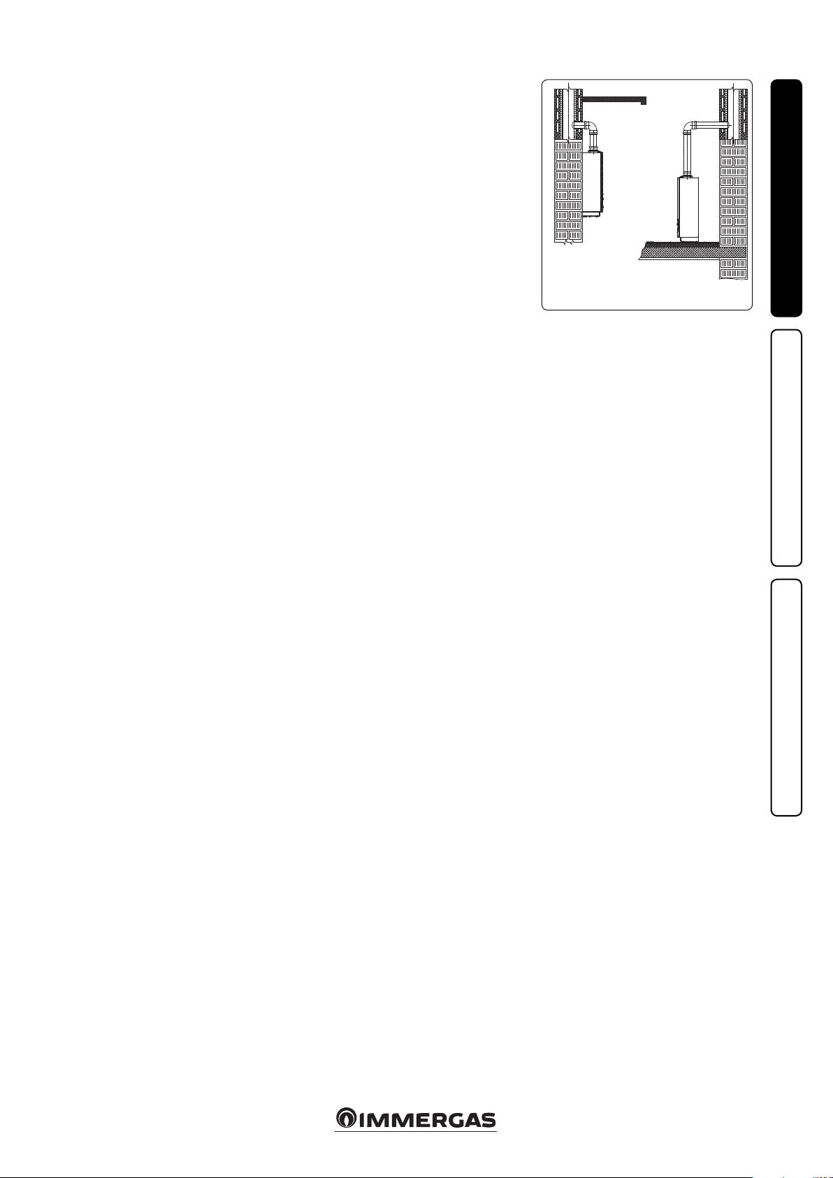
e wall surface must be smooth, without any
protrusions or recesses enabling access to the
rear part. ey are not designed to be installed
on plinths or oors (Fig. 1).
By varying the type of installation the classica-
tion of the boiler also varies, precisely:
- Type B23 or B53 boiler if installed using the
relevant terminal for air intake directly from
the room in which the boiler has been installed.
- Type C boiler if installed using concentric
pipes or other types of pipes envisioned for
the sealed chamber boiler for intake of air and
expulsion of ue gas.
Only professionally enabled companies are
authorised to install Immergas gas appliances.
Installation must be carried out according to
regulation standards, current legislation and in
compliance with local technical regulations and
the required technical procedures.
Important: the manufacturer declines all liability
for damages caused by boilers removed from
other systems or for any non-conformities of
such equipment.
Before installing the appliance, ensure that it is
delivered in perfect condition; if in doubt, contact
the supplier immediately. Packing materials (sta-
ples, nails, plastic bags, polystyrene foam, etc.)
constitute a hazard and must be kept out of the
reach of children. If the appliance is installed in-
side or between cabinets, ensure sucient space
for normal servicing; therefore it is advisable to
leave clearance of at least 3 cm between the boiler
casing and the vertical sides of the cabinet. Leave
adequate space above the boiler for possible water
and ue removal connections. Keep all amma-
ble objects away from the appliance (paper, rags,
plastic, polystyrene, etc.).
Do not place household appliances underneath
the boiler as they could be damaged if the safety
valve intervenes, if the drain trap is blocked, or
if there are leaks from the hydraulic connec-
tions; otherwise, the manufacturer cannot be
held responsible for any damage caused to the
household appliances.
For the aforementioned reasons, we recommend
not placing furnishings, furniture, etc. under
the boiler.
In the event of malfunctions, faults or incorrect
operation, turn the appliance o immediately
and contact an authorised company (e.g. the
Immergas Technical Assistance centre, which
has specically trained sta and original spare
parts). Do not attempt to modify or repair the
appliance alone.
Failure to comply with the above implies personal
responsibility and invalidates the warranty.
•Installation Standards:
- this boiler can be installed outdoors in a
partially protected area. A partially protected
area is one in which the boiler is not exposed
to the direct action of the weather (rain, snow,
hail, etc..).
is type of installation is only possible when
permitted by the laws in force in the appliance's
country of destination.
- Installation of gas appliances, ue exhaust
pipes and combustion air intake pipes is
forbidden in places with a re risk (for ex-
ample: garages, closed parking stalls), and
in potentially dangerous places.
- Installation is prohibited on the vertical
projection of the cooking surface.
- Installation is forbidden in places/rooms
that constitute public areas of apartment
buildings, internal stairways or other escape
routes (e.g. oor landings, entrance halls,
etc.).
- Installation is also forbidden in places/rooms
that constitute public areas of apartment
buildings such as cellars, entrance halls, attics,
los, etc., unless otherwise provided for by
local regulations in force.
Attention: installing the wall recessed frame
kit must guarantee the boiler stable, ecient
support. e recessed frame kit ensures ap-
propriate support only if installed correctly
(according to the rules of good practice),
following the instructions on its instructions
leaet. e recessed frame for the boiler is not
a supporting structure and must not replace
the wall removed. It is necessary to position
the boiler inside the wall. For safety reasons
against any leaks it is necessary to plaster the
boiler housing in the brick wall.
Attention: wall mounting of the boiler must
guarantee stable and ecient support for the
generator.
e plugs (standard supply) are only to be used
to x the boiler to the wall; they only ensure
adequate support if inserted correctly (according
to technical standards) in walls made of solid or
semi-hollow brick or block. In the case of walls
made from hollow brick or block, partitions with
limited static properties, or in any case walls
other than those indicated, a static test must be
carried out to ensure adequate mount.
ese boilers are used to heat water to below
boiling temperature in atmospheric pressure.
ey must be connected to a central heating
system and domestic hot water circuit suited to
their performance and capacity.
Attention: the storage tank unit must also be
installed in an environment in which the tem-
perature cannot fall below 0°C.
"Anti-legionella" heat treatment of the storage
tank (activated by the specic function present
on the predisposed thermoregulation systems):
during this stage, the temperature of the water
inside the storage tank exceeds 60°C with a
relative risk of burns. Keep this domestic hot
water treatment under control (and inform
the users) to prevent unforeseeable damage
to people, animals, things. If required install a
thermostatic valve on the domestic hot water
outlet to prevent scalding.
YES NO
6
2
INSTALLERUSERMAINTENANCE TECHNICIAN
1.2 MAIN DIMENSIONS.
Key:
V - Electrical connection
G - Gas supply
RU - Storage tank unit return
(optional)
MU - Storage tank unit ow (optional)
RR - System lling
SC - Condensate drain (minimum
internal diameter Ø 13 mm)
M - System ow
R - System return
1.3 ANTIFREEZE PROTECTION.
Minimum temperature -5°C. e boiler comes
standard with an antifreeze function that ac-
tivates the pump and burner when the system
water temperature in the boiler falls below 4°C.
In these conditions the boiler is protected against
freezing to an ambient temperature of -5°C.
Minimum temperature -15°C. If the boiler is
installed in a place where the temperature drops
below -5°C, the appliance can freeze.
To prevent the risk of freezing follow the instruc-
tions below:
- protect the central heating circuit from freezing
by inserting a good-quality antifreeze liquid
into this circuit, which is specially suited for
central heating systems and which is manu-
facturer guaranteed not to cause damage to
the heat exchanger or other components of
the boiler. e antifreeze liquid must not be
harmful to one's health. e instructions of the
manufacturer of this liquid must be followed
scrupulously regarding the percentage neces-
sary with respect to the minimum temperature
at which the system must be kept.
Attention: the excessive use of glycol could
jeopardise the proper functioning of the ap-
pliance.
An aqueous solution must be made with poten-
tial pollution class of water 2 (EN 1717:2002 or
local standards in force).
e materials used for the central heating circuit
of Immergas boilers withstand ethylene and
propylene glycol based antifreeze liquids (if the
mixtures are prepared perfectly).
For life and possible disposal, follow the sup-
plier's instructions.
- Protect the domestic hot water circuit against
freezing by using an accessory that is supplied
on request (antifreeze kit) comprising two
electric heating elements, the relevant wiring
and a control thermostat (carefully read the
installation instructions contained in the ac-
cessory kit pack).
In these conditions the boiler is protected against
freezing to temperature of -15°C.
Boiler antifreeze protection (both -5°C and -15°C)
is thus ensured only if:
- the boiler is correctly connected to gas and elec-
tricity power supply circuits;
- the boiler is powered constantly;
- the boiler is not in “o” mode.
- the boiler is not in anomaly conditions (Parag.
2.5);
- the essential components of the boiler and/or
antifreeze kit are not faulty.
e warranty does not cover damage due to inter-
ruption of the electrical power supply and failure
to comply with that stated on the previous page.
N.B.: if the boiler is installed in places where
the temperature falls below 0°C the domestic
hot water and central heating attachment pipes
must be insulated.
e water in the storage tank unit is not protected
against freezing when the boiler is switched o.
Height
(mm)
Width
(mm)
Depth
(mm)
748 440 256
CONNECTIONS
GAS D.H.W. SYSTEM
G RR R M
3/4” 1/2” 3/4” 3/4”
7
1
2
3
3
1
4
2
2
1
4
5
6
5
6
5
4
3
INSTALLERUSERMAINTENANCE TECHNICIAN
1.4 INSTALLATION INSIDE A
RECESSED FRAME OPTIONAL.
e boiler is designed for installation inside the
Immergas recessed frame (supplied as optional).
e necessary parts for this type of installation
(brackets) must also be purchased separately as
optional kit.
To install proceed as follows:
- Install the bracket (2) inside the recessed frame
xing it with the screws (3) in the pre-drilled
holes (Fig. 3).
- Hang the boiler (4) to the bracket (2) (Fig. 4).
- Block the boiler (4) by mounting the brackets
(5) and xing them with their screws (6) (Fig.
5).
e brackets (5) used to centre the boiler on
the frame and hold it in place stop against the
frame (1) so do not require xing to the frame
itself.
8
1
2
3
G
V
RU MU
RR
R
SC
M
4
6
INSTALLERUSERMAINTENANCE TECHNICIAN
Key:
V - Electrical connection
G - Gas supply
RU - Storage tank unit return (optional)
MU - Storage tank unit ow (optional)
RR - System lling
SC - Condensate drain (minimum internal diame-
ter Ø 13 mm)
M - System ow
R - System return
1 - System lling valve
2 - System draining valve
3 - 3 bar safety valve drain tting signal
4 - Bypass (Note: to disassemble if coupled with
an external storage tank unit)
1.5 BOILER CONNECTION UNIT.
e connection unit consisting of all the nec-
essary parts to perform the hydraulic and gas
system connections of the appliance comes as
optional kit, perform the connections respecting
the arrangement of Fig. 6 based on the type of
installation to be made.
1.6 GAS CONNECTION.
Our boilers are designed to operate with methane
gas (G20) and LPG. Supply pipes must be the
same as or larger than the 3/4”G boiler tting.
Before connecting the gas line, carefully clean
inside all the fuel feed system pipes to remove
any residue that could impair boiler eciency.
Also make sure the gas corresponds to that for
which the boiler is prepared (see boiler data
nameplate). If dierent, the boiler must be con-
verted for operation with the other type of gas
(see converting appliance for other gas types). It
is also important to check the dynamic pressure
of the mains (methane or LPG) used to supply the
boiler, which must comply with EN 437 and its
attachment, as insucient levels may reduce gen-
erator output and cause discomfort to the user.
Ensure correct gas cock connection. e gas
supply pipe must be suitably dimensioned
according to current regulations in order to
guarantee correct gas ow rate to the burner even
in conditions of maximum generator output and
to guarantee appliance eciency (technical spec-
ications). e coupling system must conform to
standards in force.
Fuel gas quality. e appliance was designed to
operate with combustible gas free of impurities;
otherwise it is advisable to fit special filters
upstream of the appliance to restore the purity
of the fuel.
Storage tanks (in case of supply from LPG
depot).
- New LPG storage tanks may contain residual
inert gases (nitrogen) that degrade the mixture
delivered to the appliance casing functioning
anomalies.
- Due to the composition of the LPG mixture,
layering of the mixture components may occur
during the period of storage in the tanks. is
can cause a variation in the heating power of
the mixture delivered to the appliance, with
subsequent change in its performance.
1.7 HYDRAULIC CONNECTION.
Attention: in order not to void the condensa-
tion module warranty, before making the boiler
connections, carefully wash the heating system
(pipes, radiators, etc.) with special pickling or
descaling products to remove any deposits that
could compromise correct boiler operation.
A treatment of the heating and water system
water is required, in compliance with the tech-
nical standards in force, in order to protect the
system and the appliance from deposits (e.g.
scale), slurry or other hazardous deposits. In
order not to void the heat exchanger warranty,
you are required to comply with what has been
prescribed in Paragraph 1.23.
Water connections must be made in a rational
way using the couplings on the boiler template.
Attention: the manufacturer declines all liability
in the event of damage caused by the installation
of an automatic lling system.
In order to meet the system requirements es-
tablished by EN 1717 in terms of pollution of
drinking water, we recommend installing the
IMMERGAS anti-backow kit to be used up-
stream of the cold water inlet connection of the
boiler. We also recommend using a category 1, 2
or 3 heat transfer uid (ex: water +glycol) in the
boiler's primary circuit (C.H. circuit), as dened
in standard EN 1717.
Attention: to preserve the duration and the e-
ciency features of the appliance, in the presence
of water whose features can lead to the deposit of
scale, installation of the “polyphosphate dispenser”
kit is recommended.
3 bar safety valve. Discharge of the safety valve
has been conveyed to the condensate drain trap
outlet. Consequently, in the event of valve in-
tervention, the discharged liquid will end up in
the sewer system through the drain pipe of the
condensate drain trap.
In any case the lower part of the appliance is
tted with a drain tting (Ref. 3 Fig. 6) with the
relative closure cap to check for the presence of
liquid in the discharge circuit and to check the
intervention of the 3 bar safety valve.
Condensate drain. To drain the condensate pro-
duced by the appliance, it is necessary to connect
to the drainage system by means of acid conden-
sate resistant pipes, with an internal Øof at least
13 mm. e system connecting the appliance to
the drainage system must be carried out in such
a way as to prevent occlusion and freezing of the
liquid contained in it. Before appliance ignition,
ensure that the condensate can be correctly re-
moved. Aer rst ignition, check that the drain
trap is lled with condensate (Para. 1.25). Also,
comply with national and local regulations on
discharging waste waters.
In the event condensate is not discharged into
the wastewater drainage system, a condensate
neutraliser must be installed to ensure com-
pliance with the parameters established by the
legislation in force.
9
b
2
3
d
a
1
c
2
8
7
INSTALLERUSERMAINTENANCE TECHNICIAN
1.8 ELECTRICAL CONNECTION:
e appliance has an IPX5D protection degree;
electrical safety of the appliance is achieved only
when it is connected properly to an ecient
earthing system, as specied by current safety
standards.
Attention: the manufacturer declines any
responsibility for damage or physical injury
caused by failure to connect the boiler to an
ecient earth system or failure to comply with
the reference standards.
•Open the control panel connections compart-
ment (Fig. 7).
To carry out electrical connections, all you have
to do is open the connections compartment as
follows (Fig. 7):
- Disassemble the cover (Fig. 52).
- Disassemble the cover (b)
1) Loosen the screw (a).
2) Press the two hooks on the connections
compartment cover.
3) Remove the cover (b) from the control
panel (c).
- At this point, it is possible to access the terminal
board (d).
Also ensure that the electrical installation cor-
responds to maximum absorbed power speci-
cations as shown on the boiler data nameplate.
Boilers are supplied complete with an “X” type
power cable without plug. e power supply cable
must be connected to a 230V ±10% / 50Hz mains
supply respecting L-N polarity and earth connec-
tion; this network must also have a multi-pole
circuit breaker with class III overvoltage category.
To protect from possible dispersions of DC volt-
age, it is necessary to provide a type A dierential
safety device.
When replacing the power supply cable, con-
tact a qualied company (e.g. the Authorised
Aer-Sales Technical Assistance Service). e
power cable must be laid as shown (Fig. 6).
In the event of mains fuse replacement on the
P.C.B., use a 3.15A quick-blow fuse. For the
main power supply to the appliance, never use
adapters, multiple sockets or extension leads.
N.B.: connect terminals 36 and 37 to electrically
connect the boiler to the storage tank unit, elimi-
nating resistance R8 in the boiler (Fig. 37).
Installation with system operating at direct
low temperature. e boiler can directly supply
a low-temperature system by setting the ow
temperature adjustment range “t0” and “t1” (Par.
3.8). In this situation it is good practice to insert
a relevant safety kit (optional) made up from a
thermostat (with adjustable temperature). e
thermostat must be positioned on the system
ow pipe at a distance of at least 2 metres from
the boiler.
1.9 REMOTE CONTROLS AND
ROOM CHRONOTHERMOSTATS
OPTIONAL.
e boiler is prepared for the application of room
chrono-thermostats or remote controls, which
are available as optional kits (Fig. 8).
All Immergas chrono-thermostats are connected
with 2 wires only. Carefully read the user and
assembly instructions contained in the acces-
sory kit.
•On/O Immergas digital chrono-thermostat.
e chrono-thermostat allows:
- set two room temperature value: one for day
(comfort temperature) and one for night
(reduced temperature);
- set a weekly programme with four daily
switch on and switch o times;
- selecting the required function mode from
the various possible alternatives:
•manual operation (with adjustable tempera-
ture).
•automatic operation (with set programme).
•forced automatic operation (momentarily
changing the temperature of the automatic
programme).
e chrono-thermostat is powered by two 1.5V
LR 6 type alkaline batteries.
•Comando Amico Remoto Remote Control De-
vice V2 (CARV2) with climate chrono-thermostat
function. In addition to the functions described
in the previous point, the CARV2 panel enables
the user to control all the important informa-
tion regarding operation of the appliance and
the heating system with the opportunity to
easily intervene on the previously set parame-
ters, without having to go to where the appli-
ance is installed. e panel is provided with
self-diagnosis to display any boiler functioning
anomalies. The climate chrono-thermostat
incorporated into the remote panel enables
the system ow temperature to be adjusted to
the actual needs of the room being heated, in
order to obtain the desired room temperature
with extreme precision and therefore with
evident saving in running costs. e CARV2 is
fed directly by the boiler by means of the same 2
wires used for the transmission of data between
the boiler and device.
Comando Amico Remoto Remote Control V2
or On/Ochrono-thermostat electrical con-
nections (Optional). e operations described
below must be performed aer having removed
the voltage from the appliance. Any thermostat
or On/O environment chrono-thermostat must
be connected to clamps 44/40 and 41 eliminating
jumper X40 (Fig. 37). Make sure that the On/
O thermostat contact is of the “clean” type, i.e.
independent of the mains voltage, otherwise the
P.C.B. would be damaged. Any Comando Amico
Remoto Remote Control V2 must be connected
to clamps 44/40 and 41 eliminating jumper X40
on the P.C:B., paying attention not to invert the
polarity in the connections (Fig. 37). e boiler
can only be connected to one remote control.
Important: if the Comando Amico Remo-
to Remote Control V2 or any other On/Off
chrono-thermostat is used, arrange two separate
lines in compliance with current regulations
regarding electrical systems. No boiler pipes
must ever be used to earth the electric system or
telephone lines. Ensure elimination of this risk
before making the boiler electrical connections.
10
45
31
58
109
INSTALLERUSERMAINTENANCE TECHNICIAN
EXTERNAL PROBE
Correction law of the ow temperature depending on the external temperature
and user adjustments of the central heating temperature.
1.10 EXTERNAL TEMPERATURE PROBE
OPTIONAL.
e boiler is designed for the application of the
external temperature probe (Fig. 9), which is
available as an optional kit. Refer to the relative
instruction sheet for positioning of the external
probe.
e probe can be connected directly to the boiler
electrical system and allows the max. system ow
temperature to be automatically decreased when
the external temperature increases, in order to
adjust the heat supplied to the system according
to the change in external temperature. e ex-
ternal probe always operates when connected,
regardless of the presence or type of room
chrono-thermostat used and can work in combi-
nation with Immergas chrono-thermostats. e
correlation between system ow temperature
and external temperature is determined by the
position of the central heating selector switch on
the boiler control panel (or on the CARV2 control
panel if connected to the boiler) according to
the curves shown in the diagram (Fig. 10). e
electric connection of the external probe must be
made on clamps 38 and 39 on the terminal board
in the boiler control panel (Fig. 37).
Position of the central heating temperature
user adjustment
11
(A)
(B)
11
INSTALLERUSERMAINTENANCE TECHNICIAN
1.11 IMMERGAS FLUE SYSTEMS.
Immergas supplies various solutions separately
from the boilers regarding the installation of
air intake terminals and ue exhaust, which are
fundamental for boiler operation.
Attention: the boiler must be installed ex-
clusively with an original Immergas “Green
Range”inspectionable air intake system and
flue gas extraction system made of plastic,
with the exception of the C6 conguration, as
required by the regulations in force.
e plastic pipes cannot be installed outdoors,
for tracts longer than 40 cm, without suitable
protection from UV rays and other atmos-
pheric agents.
is ue can be identied by an identication
mark and special distinctive marking bearing
the note "only for condensation boilers".
•Resistance factors and equivalent lengths. Each
ue component has a Resistance Factor based
on experimental tests and specied in the table
below. e Resistance Factor for individual
components is independent from the type of
boiler on which it is installed and has a dimen-
sionless size. It is however, conditioned by the
temperature of the uids that pass through the
pipe and therefore, varies according to applica-
tions for air intake or ue exhaust. Each single
component has a resistance corresponding to
a certain length in metres of pipe of the same
diameter; the so-called equivalent length,
can be obtained from the ratio between the
relative Resistance Factors. All boilers have an
experimentally obtainable maximum Resistance
Factor equal to 100. e maximum Resistance
Factor allowed corresponds to the resistance
encountered with the maximum allowed pipe
length for each type of Terminal Kit. This
information allows calculations to be made to
verify the possibility of setting up various ue
congurations.
•Positioning of the gaskets (black) for “green
range”ue extraction systems. Position the
gasket correctly (for bends and extensions)
(Fig. 11):
- gasket (A) with notches, to use for bends;
- gasket (B) without notches, to use for exten-
sions;
N.B.: if necessary, to ease the push-fitting,
spread the elements with commonly-used talc.
•Coupling extension pipes and concentric
elbows. To install push-tting extensions with
other elements of the ue, proceed as follows:
Install the concentric pipe or elbow with the
male side (smooth) on the female side (with lip
seal) to the end stop on the previously installed
element in order to ensure sealing eciency of
the coupling.
Attention: if the exhaust terminal and/or
concentric extension pipe needs shortening,
consider that the internal duct must always
protrude by 5 mm with respect to the external
duct.
•N.B.: for safety purposes, do not obstruct the
boiler intake/exhaust terminal, even temporar-
ily.
•N.B.: when installing horizontal pipes, a min-
imum inclination of 3% must be maintained
and a section clip with pin must be installed
every 3 metres.
•Installation inside the recessed frame. In this
mode, install the ue according to your needs
using the appropriate pre-sections in the frame
to exit from its clearances.
1.12 TABLES OF RESISTANCE FACTORS
AND EQUIVALENT LENGTHS.
TYPE OF DUCT
Resistance
Factor
(R)
Equivalent length
in m of concentric
pipe Ø80/125
Concentric pipe 80/125 Øm 1 2.1 1
Concentric bend 90° 80/125 Ø3.0 1.4
Concentric bend 45° 80/125 Ø2.1 1
Terminal complete with concentric
horizontal intake-exhaust Ø80/125 2.8 1.3
Terminal complete with concentric
vertical intake-exhaust 80/125 Ø3.6 1.7
Concentric bend 90° Ø80/125 with
inspection 3.4 1.6
Stub pipe with inspection Ø80/125 3.4 1.6
12
INSTALLERUSERMAINTENANCE TECHNICIAN
TYPE OF DUCT
Resistance
Factor
(R)
Equivalent length
in m of concentric
pipe Ø60/100
Equivalent length
in metres of pipe
Ø80
Equivalent length
in metres of pipe
60 Ø
Equivalent length
in m of concentric
pipe Ø80/125
Concentric pipe Ø60/100
m 1
Intake and
Exhaust 6.4 m 1 Intake m 7.3 Exhaust m 1.9 m 3.0
Exhaust m 5.3
Concentric bend 90° Ø
60/100
Intake and
Exhaust 8.2 1.3 m Intake m 9.4 Exhaust m 2.5 m 3.9
Exhaust m 6.8
Concentric bend 45° Ø
60/100
Intake and
Exhaust 6.4 m 1 Intake m 7.3 Exhaust m 1.9 m 3.0
Exhaust m 5.3
Terminal complete with
concentric horizontal
intake-exhaust Ø60/100
Intake and
Exhaust 15 m 2.3
Intake m 17.2
Exhaust m 4.5 m 7.1
Exhaust m 12.5
Concentric horizontal
intake- exhaust terminal
Ø60/100
Intake and
Exhaust 10 m 1.5 Intake m 11.5 Exhaust m 3.0 4.7 m
Exhaust m 8.3
Terminal complete with
concentric vertical in-
take-exhaust Ø60/100
Intake and
Exhaust 16.3 m 2.5
Intake m 18.7
Exhaust m 4.9 m 7.7
Exhaust m 13.6
Concentric vertical
intake-exhaust terminal Ø
60/100
Intake and
Exhaust 9 1.4 m
Intake m 10.3
Exhaust m 2.7 m 4.3
Exhaust m 7.5
Pipe Ø80 m 1 Intake 0.87 m 0.1 Intake m 1.0 Exhaust m 0.4 m 0.4
m 0.5
Exhaust 1.2 m 0.2 Exhaust m 1.0
Complete intake terminal
Ø80 m 1 Intake 3 m 0.5 Intake m 3.4 Exhaust m 0.9 1.4 m
Intake terminal Ø80
Exhaust terminal Ø80
Intake 2.2 m 0.35 Intake m 2.5 Exhaust m 0.6 m 1
m 0.9
Exhaust 1.9 m 0.3 Exhaust m 1.6
Bend 90° 80 ØIntake 1.9 m 0.3 Intake m 2.2 Exhaust m 0.8 m 0.9
m 1.2
Exhaust 2.6 m 0.4 Exhaust m 2.1
45° 80 ØBend Intake 1.2 m 0.2 Intake m 1.4 Exhaust m 0.5 m 0.5
0.7
Exhaust 1.6 m 0.25 Exhaust m 1.3
Pipe Ø60 m 1 for ducting Exhaust 3.3 m 0.5 Intake 3.8 Exhaust m 1.0 m 1.5
Exhaust 2.7
Bend 90° Ø60 for ducting Exhaust 3.5 m 0.55 Intake 4.0 Exhaust m 1.1 1.6 m
Exhaust 2.9
Reduction Ø80/60 Intake and
Exhaust 2.6 m 0.4 Intake m 3.0 Exhaust m 0.8 m 1.2
Exhaust m 2.1
Terminal complete with
exhaust
vertical Ø60 for ducting
Exhaust 12.2 1.9 m
Intake m 14
Exhaust m 3.7 m 5.8
Exhaust m 10.1
13
1413
12
INSTALLERUSERMAINTENANCE TECHNICIAN
1.13 OUTDOOR INSTALLATION IN
PARTIALLY PROTECTED AREA.
N.B.: a partially protected location is one in which
the appliance is not exposed to the direct action of
the weather (rain, snow, hail, etc..)..
•Conguration type B, open chamber and fan
assisted.
Using the special coverage kit one can achieve
direct air intake (Fig. 12) and ue gas exhaust
in a single chimney or directly outside. In this
conguration it is possible to install the boiler in
a partially protected place. In this conguration
the boiler is classied as type B.
With this conguration:
- air intake takes place directly from the envi-
ronment in which the appliance is installed
(external);
- the ue gas exhaust must be connected to its
own single ue (B23) or ducted directly outside
via a vertical terminal for direct exhaust (B53)
or via an Immergas ducting system (B53).
The technical regulations in force must be
respected.
•Coverage kit assembly (Fig. 13). Remove the
two plugs from the lateral intake holes. Now
cover the le intake hole using the relevant
plate, xing it onto the right side using the 2
previously-removed screws. Install the Ø80
outlet ange on the central hole of the boiler,
taking care to insert the gasket supplied with
the kit and tighten by means of the screws
provided. Install the upper cover, xing it using
the 4 screws present in the kit, positioning the
relevant gaskets. Engage the 90° Ø80 bend
with the male end (smooth) in the female end
(with lip seal) of the Ø80 ange unit until
it stops. Introduce the gasket, making it run
along the bend. Fix it using the metal sheet
plate and tighten by means of the clips present
in the kit, making sure to block the 4 gasket
aps. Fit the male end (smooth) of the exhaust
terminal into the female end of the bend 90° Ø
80, making sure that the relevant wall sealing
plate is already tted; this will ensure hold and
joining of the elements making up the kit.
Max. length of exhaust duct. e ue pipe (both
vertical or horizontal) can be extended to a max.
length of 30 linear metres.
•Coupling of extension pipes. To install
push-tting extensions with other elements
of the ue, proceed as follows: Install the pipe
or elbow with the male side (smooth) in the
female section (with lip seal) to the stop on the
previously installed element. is will ensure
sealing eciency of the coupling.
•Conguration without cover kit in a partially
protected location (type C boiler)
N.B.: a partially protected location is one in
which the appliance is not exposed to the direct
action of the weather (rain, snow, hail, etc..)..
By leaving the side plugs tted it is possible
to install the appliance externally without the
cover kit. Installation takes place using the
Ø60/100 and Ø80/125 concentric intake/
exhaust kits. Refer to the paragraph on indoor
installation. In this conguration the upper
cover kit guarantees additional protection for
the boiler. It is recommended but not compul-
sory. e Ø80/80 separating device cannot be
used in this conguration.
e cover kit includes:
N° 1 Heat moulded cover
N°1 Gasket clamping plate
N°1 Gasket
N°1 Gasket clamp
N°1 N°1 Intake hole covering plate
e terminal kit includes:
N° 1 Gasket
N° 1 Exhaust ange Ø 80
N° 1 Bend 90° 80 Ø
N° 1 Exhaust pipe Ø 80
N° 1 Wall sealing plate
14
16
15
INSTALLERUSERMAINTENANCE TECHNICIAN
1.14 INTERNAL INSTALLATION USING
A RECESSED FRAME WITH DIRECT
AIR INTAKE
•Conguration type B, open chamber and fan
assisted.
Using a kit separator one can achieve direct air
intake (Fig. 16) and ue gas exhaust in a single
chimney or directly outside. In this conguration
the boiler is classied as type B23.
With this conguration:
- air intake takes place directly from the envi-
ronment in which the appliance is installed
(the recessed frame is ventilated), and only
functions in permanently ventilated rooms;
- the ue gas exhaust must be connected to its
own individual ue or channelled directly into
the external atmosphere.
The technical regulations in force must be
respected.
Separator kit installation: install the discharge
ange on the central hole of the boiler, posi-
tioning the relative gasket with the circular
projections downwards in contact with the
boiler ange, and tighten using the hex screws
with at tip contained in the kit. Remove the at
ange present in the lateral hole with respect to
the central one (according to needs) and replace
it with the intake ange, positioning its gasket
already present in the boiler and tighten using
the supplied self-threading screws. Fit the male
side (smooth) to the bends in the female side of
the anges.
e intake bend must face the rear side of the
boiler.
Fit the exhaust pipe with the male side (smooth)
to the female side of the bend up to the end stop,
making sure that the internal wall sealing plate
has been tted and connecting the required ue
according to personal requirements.
Max. length of exhaust duct. e ue pipe (both
vertical or horizontal) can be extended to a max.
length of 30 linear metres.
15
C13
5
4
3
1
2
1
2
3
456
C13
C13
C13
20
18
19
17
INSTALLERUSERMAINTENANCE TECHNICIAN
e kit includes:
N° 1 - Gasket (1)
N° 1 - Concentric bend Ø 60/100 (2)
N° 1 - Int./exhaust concentric terminal Ø 60/100 (3)
N° 1 - Internal wall sealing plate (4)
N° 1 - External wall sealing plate (5)
e adaptor kit includes:
N° 1 - Gasket (1)
N° 1 - Adapter Ø 80/125 (2)
1.15 CONCENTRIC HORIZONTAL KIT
INSTALLATION.
Type C configuration, sealed chamber and
fan assisted.
e position of the terminal (in terms of distanc-
es from openings, overlooking buildings, oor,
etc.) must be in compliance with the regulations
in force.
is terminal is connected directly to the outside
of the building for air intake and ue gas exhaust.
e horizontal kit can be installed with the rear,
right side, le side or front outlet. For installation
with frontal outlet, one must use the xing plate
and a concentric bend coupling in order to ensure
sucient space to carry out the tests required by
law upon commissioning.
•External grid. Both the Ø60/100 and Ø80/125
intake/exhaust terminal, if properly installed, is
pleasant to look at on the outside of the build-
ing. Make sure that the external silicone wall
sealing plate is properly inserted in the wall.
N.B.: for proper system operation the terminal
with grid must be installed correctly ensuring
that, the "high" indication on the terminal is
observed during installation.
Horizontal intake-exhaust kit Ø60/100. Kit
assembly (Fig. 17): install the bend with ange
(2) on the central hole of the boiler, positioning
gasket (1) with the circular projections down-
wards in contact with the boiler flange, and
tighten using the screws present in the kit. Fit
the Ø60/100 (3) concentric terminal pipe with
the male side (smooth) to the female side of the
bend (2) up to the end stop; making sure that the
internal and external wall sealing plate have been
tted, this will ensure sealing and joining of the
elements making up the kit.
•Extensions for Ø60/100 horizontal kit (Fig. 18).
e kit with this conguration can be extended
up to a max. 12.9 horizontal m including the
terminal with grid and excluding the concen-
tric bend leaving the boiler. is conguration
corresponds to a resistance factor of 100. In this
case the special extensions must be requested.
Immergas also provides a Ø60/100 simplied
terminal, which in combination with its ex-
tension kits allows you to reach a maximum
extension of 11.9 metres.
Horizontal intake-exhaust kit Ø80/125. Kit
assembly (Fig. 19): to install the kit Ø80/125
one must use the anged adapter kit in order
to install the ue system Ø80/125. Install the
anged adaptor (2) on the central hole of the
boiler, positioning gasket (1) with the circular
projections downwards in contact with the boiler
ange, and tighten using the screws contained in
the kit. Engage the bend (3) with the male side
(smooth) to the end stop on the adapter (1). Fit
the Ø80/125 (5) concentric terminal pipe with
the male side (smooth) to the female side of the
bend (4) (with lip seals) up to the end top; making
sure that the internal (6) and external wall sealing
plate (7) have been tted, this will ensure sealing
and joining of the elements making up the kit.
•Extensions for Ø80/125 horizontal kit (Fig. 20).
e kit with this conguration can be extended
up to a max. length of 32 m, including the termi-
nal with grid and excluding the concentric bend
leaving the boiler. If additional components
are assembled, the length equivalent to the
maximum allowed must be subtracted. In this
case the special extensions must be requested.
e Kit Ø 80/125 includes:
N° 1 - Concentric bend Ø 80/125
at 87° (3)
N° 1 - Concentric intake-exhaust
terminal Ø 80/125 (4)
N° 1 - Internal wall sealing plate (5)
N° 1 - External wall sealing plate (6)
e remaining kit components
must not be used
16
C33
C33
C33
C33
7
46
5
1
2
3
1
2
3
4
5
6
7
24
22
23
21
INSTALLERUSERMAINTENANCE TECHNICIAN
e Kit includes:
N° 1 - Gasket (1)
N° 1 - Female concentric ange (2)
N° 1 - Wall sealing plate (3)
N° 1 - Aluminium tile (4)
N° 1 - Int./exhaust concentric pipe Ø
60/100 (5)
N° 1 - Fixed half-shell (6)
N° 1 - Mobile half-shell (7)
e adaptor kit includes:
N° 1 - Gasket (1)
N° 1 - Adapter
Ø 80/125 (2)
e Kit Ø 80/125 includes:
N° 1 - Wall sealing plate (3)
N° 1 - Aluminium tile (4)
N° 1 - Fixed half-shell (5)
N° 1 - Mobile half-shell (6)
N° 1 - Concentric intake-exhaust
terminal Ø 80/125 (7)
e remaining kit components
must not be used
1.16 CONCENTRIC VERTICAL KIT
INSTALLATION.
Type C configuration, sealed chamber and
fan assisted.
Concentric vertical intake and exhaust kit. is
vertical terminal is connected directly to the
outside of the building for air intake and ue
gas exhaust.
N.B.: the vertical kit with aluminium tile enables
installation on terraces and roofs with a maxi-
mum slope of 45% (approx 25°) and the height
between the terminal cap and half-shell (374 mm
for Ø60/100 and 260 mm for Ø80/125) must
always be observed.
Vertical kit with aluminium tile Ø60/100.
Kit assembly (Fig. 21): install the concentric
ange (2) on the central hole of the boiler, posi-
tioning gasket (1) with the circular projections
downwards in contact with the boiler ange, and
tighten using the screws contained in the kit.
Installation of the fake aluminium tile: replace
the tiles with the aluminium sheet (4), shaping
it to ensure that rainwater runs o. Position
the xed half-shell (6) on the aluminium tile
and insert the intake-exhaust pipe (5). Fit the
Ø60/100 (3) concentric terminal pipe with the
male side (5) (smooth) into the ange (2) up to
the end stop; making sure that the wall sealing
plate has been tted (3), this will ensure sealing
and joining of the elements making up the kit.
N.B.: when the boiler is installed in areas where
very cold temperatures can be reached, a special
anti-freeze kit is available that can be installed as
an alternative to the standard kit.
•Extensions for vertical kit Ø60/100 (Fig. 22).
e kit with this conguration can be extended
to a max. straight vertical length of 14.4 m,
including the terminal. This configuration
corresponds to a resistance factor of 100. In
this case specic extensions must be requested.
Vertical kit with aluminium tile Ø80/125.
Kit assembly (Fig. 23): to install the kit Ø80/125
one must use the anged adapter kit in order
to install the ue system Ø80/125. Install the
anged adaptor (2) on the central hole of the
boiler, positioning gasket (1) with the circular
projections downwards in contact with the boiler
ange, and tighten using the screws contained
in the kit. Installation of the fake aluminium
tile: replace the tiles with the aluminium sheet
(4), shaping it to ensure that rainwater runs o.
Position the xed half-shell (5) on the aluminium
tile and insert the intake-exhaust pipe (7). Fit the
Ø80/125 concentric terminal pipe with the male
side (smooth) to the female side of the adapter (1)
(with lip gaskets) up to the end stop; making sure
that the wall sealing plate (3) has been tted, this
will ensure sealing and joining of the elements
making up the kit.
•Extensions for vertical kit Ø80/125 (Fig. 24).
e kit with this conguration can be extended
up to a max. length of 32 m including the ter-
minal. If additional components are assembled,
the length equivalent to the maximum allowed
must be subtracted. In this case specic exten-
sions must be requested.
17
C83
C43
1
4
79
556
7
8
3
2
S
A
C53*- C83
*per completare la congurazione C53 prevedere anche un terminale di scarico a
tetto. Non è ammessa la congurazione su pareti opposte all'edicio.
27
2625
INSTALLERUSERMAINTENANCE TECHNICIAN
e kit includes:
N° 1 - Exhaust gasket (1)
N° 1 - Flange gasket (2)
N° 1 - Female intake ange (3)
N° 1 - Female exhaust ange (4)
N° 2 - Bend 90° Ø 80 (5)
N° 1 - Intake terminal Ø 80 (6)
N° 2 - Internal wall sealing plates (7)
N° 1 - External wall sealing plate (8)
N° 1 - Exhaust pipe Ø 80 (9)
1.17 SEPARATOR KIT INSTALLATION.
Type C configuration, sealed chamber and
fan assisted.
Separator kit Ø80/80. is kit allows air to come
in from outside the building and the exhaust to
exit from the chimney, ue or intubated duct
through divided ue exhaust and air intake pipes.
Combustion products are expelled from pipe (S)
(in plastic, so as to resist acid condensate). Air is
taken in through duct (A) for combustion (this
is also in plastic). e intake pipe (A) can be
installed either on the right or le hand side of
the central exhaust pipe (S). Both ducts can be
routed in any direction.
•Kit assembly (Fig. 25): install ange (4) on the
central hole of the boiler, positioning gasket
(1) with the circular projections downwards
in contact with the boiler ange, and tighten
using the hex screws with at tip contained
in the kit. Remove the at ange present in
the lateral hole with respect to the central one
(according to needs) and replace it with the
ange (3), positioning the gasket (2) already
present in the boiler and tighten using the
supplied self-threading screws. Fit the male side
(smooth) to the bends (5) in the female side of
the anges (3 and 4). Fit the intake terminal (6)
with the male side (smooth) in the female side
of the bend (5) up to the end stop, ensuring that
the internal and external wall sealing plates are
tted. Fit the exhaust pipe (9) with the male
end (smooth) to the female end of the bend
(5) up to the end stop; making sure that the
internal wall sealing plate has been tted, this
will ensure sealing and joining of the elements
making up the kit.
•Installation clearances (Fig. 26). e minimum
installation clearance measurements of the Ø
80/80 separator terminal kit have been stated
in some limit conditions.
•Extensions for separator kit Ø80/80. The
maximum vertical straight length (without
bends) that can be used for Ø80 intake and
exhaust pipes is 41 metres, regardless from
whether they are used for intake or exhaust.
e maximum horizontal straight length (with
bend in suction and in exhaust) that can be
used for Ø80 intake and exhaust pipes is 36
metres, regardless from whether they are used
for intake or exhaust. Please note the type of
installation must be done with a natural
draught ue.
N.B.: to favour the removal of possible conden-
sate forming in the exhaust pipe, tilt the pipes
towards the boiler with a minimum slope of
1.5% (Fig. 27).
C43
Minimum slope 1.5%
18
12
3
3
3
4567
689
A
10
11
12
12
A
B
A
C
29
28
INSTALLERUSERMAINTENANCE TECHNICIAN
Kit composition:
Ref. Qty Description
1 1 Door adaptor Ø100 or Ø125
2 1 Door gasket made of neoprene
3 4 Screws 4.2 x 9 AF
4 1 Hex headed screw M6 x 20
5 1 Flat nylon washer M6
6 2 Door hole closure metal-sheet plate
plug
7 1 Plug gasket made of neoprene
8 1 Toothed washer M6
9 1 Nut M6
10 1 (kit 80/125) Concentric gasket Ø60-100
11 1 (kit 80/125) Flanged adapter Ø80-125)
12 4 (kit 80/125) Hex headed screws M4 x 16 slotted
- 1 (kit 80/125) Bag of lubricating talc
Installation drawings key:
Unique identication of the component in
the kit
Identication of the component not supplied
in this kit
1
A
Supplied separately:
Ref. Qty Description
A 1 Ducting kit door
Rigid Ø80
ducting (A)
mm
SHAFT
(B) mm
SHAFT
(C) mm
86 126 146
Flexible Ø80
ducting (A)
mm
SHAFT
(B) mm
SHAFT
(C) mm
90 130 150
1.18 ADAPTOR C9 KIT INSTALLATION.
is kit allows an Immergas boiler to be installed
in "C93" conguration, with combustion air intake
directly from the sha where the ue gas exhaust
is, obtained by means of a ducting system.
System composition.
e system must be combined with the following
components (sold separately) to be functional
and complete:
- kit C93 Ø100 or Ø125 version;
- rigid ducting Ø60 and Ø80 and exible Ø50
and Ø80 kit;
- ue exhaust kit Ø60/100 or Ø80/125 cong-
ured according to the installation and type of
boiler.
Kit Assembly.
- Mount the components of kit "C9" on the door
(A) of the ducting system (Fig. 29).
- (Version Ø125 only) mount the anged adap-
tor (11) interposing the concentric gasket (10)
on the boiler, tting it with the screws (12).
- Mount the ducting system as described in the
relative instructions sheet.
- Calculate the distances between the boiler drain
and the bend of the ducting system.
- Prepare the boiler ue system, making surethat
the internal pipe of the concentric kit is tted
up to the end stop in the ducting system curve
(Quota "X" Fig. 30), whereas the external pipe
must reach the end stop of the adapter (1).
N.B.: to encourage the removal of possible
condensate forming in the exhaust pipe, tilt
the pipes towards the boiler with a minimum
slope of 1.5%.
- Mount the cover (A) complete with adaptor (1)
and caps (6) on the wall and assemble the ue
system to the ducting system.
N.B.: (version Ø125 only) before assembly check
the gaskets are in the right position. In the event
component lubrication (already carried out
by the manufacturer) is not sucient, remove
the residual lubricant using a dry cloth, then
to ease tting coat the parts with common or
industrial talc.
Once all components have been assembled pro-
perly, the exhaust fumes will be expelled via the
ducting system; the combustion air for normal
boiler operation will be aspirated directly by the
sha (Fig. 30).
Technical data.
- e dimensions of the shas must ensure a
minimum gap between the outer wall of the
smoke duct and the inner wall of the sha: 30
mm for circular section shas and 20 mm in
the event of a square section sha (Fig. 28).
- Maximum 2 changes of direction are allowed
on the vertical section of the ue system with
a maximum clearance angle of 30° with respect
to the vertical.
- e maximum vertical extension using a Ø
60 ducting system is 13 m, the maximum
extension includes 1 bend Ø60/10 at 90°, 1 m
of horizontal pipe 60/100, 1 90° ducted bend
Ø60 and the roof terminal for ducting.
To determine the C93 ue system in cong-
urations other than that described (Fig. 30)
one must consider that 1 metre of ducted pipe
according to the indications described has a
resistance factor equal to 4.9.
- e maximum vertical extension using a Ø80
ducting system is 28 m, the maximum exten-
sion includes 1 adapter 60/100 to 80/125, 1 87°
bend Ø80/125, 1 m of horizontal pipe 80/125,
1 90° ducted bend Ø80 and the roof terminal
for ducting.
To determine the C93 ue system in congura-
tions other than that described (Fig. 30) one
must consider the following pressure drops:
- 1 m of concentric pipe Ø80/125 = 1 m of
ducted pipe;
- 1 87° bend = 1.4 m of ducted pipe;
Consequently one must subtract the equivalent
length of the part added to the 28 m available.
Flexible Ø50
and Rigid Ø
60 ducting (A)
mm
SHAFT
(B) mm
SHAFT
(C) mm
66 106 126
19
C53
C93
X
3130
INSTALLERUSERMAINTENANCE TECHNICIAN
1.19 DUCTING OF FLUES OR
TECHNICAL SLOTS.
Ducting is an operation through which, via
the introduction of one or more relevant pipes,
one achieves a system for the evacuation of the
combustion products of a gas appliance, made up
from the coupling of an existing or new ducting
pipe with a chimney, ue or technical slot (also
in new buildings) (Fig. 31). Ducting requires
ducts declared to be suitable for the purpose by
the manufacturer, following the installation and
user instructions, provided by the manufacturer
and the requirements of the standards in force.
Immergas ducting system. e Ø 60 rigid, Ø
80 exible and Ø80 rigid “Green Range” ducting
systems must only be used for domestic use and
with Immergas condensing boilers.
In any case, ducting operations must respect
the provisions contained in the standard and in
current technical regulations; in particular, the
declaration of conformity must be compiled at
the end of work and on commissioning of the
ducted system. e instructions in the project
or technical report must likewise be followed, in
cases provided for by the standard and current
technical regulations. e system or components
of the system have a technical life complying with
current standards, provided that:
- it is used in average atmospheric and envi-
ronmental conditions, according to current
regulations, (absence of ue gas, dusts or gases
that can alter the normal thermophysical or
chemical conditions; existence of temperatures
coming within the standard range of daily
variation, etc.).
- Installation and maintenance must be per-
formed according to the indications supplied
by the manufacturer and in compliance with
the regulations in force.
- e maximum length specied by the manu-
facturer must be respected; in this regard:
- e max. possible length of the Ø60 exible
ducting vertical section is equal to 22 m. is
length is obtained considering the complete
Ø80 exhaust terminal, 1m of Ø80 pipe in
exhaust, two 90° Ø80 bends at boiler outlet.
- e max. possible length of the Ø80 exible
ducting vertical section is equal to 30 m.
is length is obtained considering the Ø80
complete exhaust terminal, 1m of Ø80 pipe
in exhaust, two 90° Ø80 bends at boiler outlet
for connecting to the ducting system and two
direction changes of the exible hose inside
the chimney/technical slot.
- e max. possible length of the Ø80 exible
ducting vertical section is equal to 30 m. is
length is obtained considering the complete
Ø80 exhaust terminal, 1m of Ø80 pipe in
exhaust, two 90° Ø80 bends at boiler outlet.
You can also install an additional Ø50 exible
ducting system the specications of which are
found on the relevant instructions sheet inside
the kit.
1.20 CONFIGURATION TYPE B, OPEN
CHAMBER AND FAN ASSISTED FOR
INDOORS.
e appliance can be installed inside buildings
in 23 or B53 mode; in this case, all technical rules
and national and local regulations in force, must
be complied with.
- Type B open chamber boilers must not be
installed in places where commercial, artisan
or industrial activities take place, which use
products that may develop volatile vapours or
substances (e.g. acid vapours, glues, paints, sol-
vents, combustibles, etc.), as well as dusts (e.g.
dust deriving from the working of wood, coal
nes, cement, etc.), which may be damaging for
the components of the appliance and jeopardise
functioning.
- in B23 and B53 conguration, unless otherwise
provided for by local regulations, the boilers
must not be installed in bedrooms, bathrooms
or in studio ats. ey must neither be installed
in rooms containing solid fuel heat generators
nor in rooms communicating with said rooms.
- Installation of appliances in B23 and B53 con-
guration is recommended in non-residential
premises and which are permanently ventilat-
ed.
For installation the cover kit must be used, re-
ferred to in Paragraph 1.13.
1.21 FLUE EXHAUST TO FLUE/CHIMNEY.
Flue exhaust does not necessarily have to be con-
nected to a branched type traditional ue. e ue
exhaust, for boiler clots installed in C conguration,
canbe connected to aspecial LAStype multipleue.
For B23 congurations, exhaust is only allowed into
individual chimney or directly into the external
atmosphere via a relevant terminal. e multiple
ues and the combined ues must also only be
connected to type C appliances of the same type
(condensation), having nominal heat inputs that do
not dier by more than 30% less with respect to the
maximum that can be attached and powered by the
same fuel. e thermo-uid dynamic features (ue
ow rate, % of carbon dioxide, % humidity etc....) of
the appliances attached to the same multiple ues
or combined ues, must not dier by more than
10% with respect to the average boiler attached.
Multiple and combined ues must be specially
designed according to the calculation method and
requirements of the technical standards in force,
by a professionally qualied company. Chimney
or ue sections for connection of the ue exhaust
pipe must comply with requisites of technical
standards in force.
20
32
INSTALLERUSERMAINTENANCE TECHNICIAN
1.22 FLUES, CHIMNEYS AND CHIMNEY
CAPS.
e ues, chimneys and chimney caps for the
evacuation of combustion products must be in
compliance with applicable standards. Chimneys
and roof-installed exhaust terminals must com-
ply with the outlet height and with the distance
from technical volumes set forth by the technical
standards in force.
Positioning the wall ue exhaust terminals. e
wall ue exhaust terminals must:
- be installed on external perimeter walls of the
building;
- be positioned according to the minimum dis-
tances specied in current technical standards.
Combustion products exhaust of natural
draught or fan assisted appliances in open-top
closed environments. In spaces closed on all
sides with open tops (ventilation pits, court-
yards etc.), direct combustion product exhaust
is allowed for natural draught or fan assisted gas
appliances with a heat input range from 4 to 35
kW, provided the conditions as per the current
technical standards are respected.
1.23 WATER TREATMENT SYSTEM
FILLING.
As already mentioned in the previous para-
graphs, a treatment of the thermal and domestic
system water is required, in compliance with the
local standards in force.
e parameters that inuence the duration and
proper operation of the heat exchanger are the
water's PH, hardness, conductivity, and oxygen,
together with the system's processing residues
(any welding residues), any oil present and cor-
rosion products that can, in turn, cause damage
to the heat exchanger.
In order to prevent this from happening, you are
recommended to:
- Before installation on new systems as well as
old ones, clean the system with clean water to
eliminate solid residues contained therein.
- Clean the system with a chemical treatment:
- Clean the new system with a suitable cleaning
device (for example Sentinel X300, Fernox
Cleaner F3 or Jenaqua 300) combined with
thorough washing.
- Clean the old system with a suitable cleaning
device (for example Sentinel X400 or X800,
Fernox Cleaner F3 or Jenaqua 400) combined
with thorough washing.
- Check the maximum hardness and quantity
of lling water referring to the graphics (Fig.
32). If the contents and hardness of the water
are below the indicated curve, no specific
treatment is required; otherwise, to limit the
content of calcium carbonate, you must provide
for water-lling treatment.
- Should you be required to provide for water
treatment, this should be carried out by
completely desalinating the lling water. As
opposed to the complete soening process,
desalinating the water completely not only
removes hardening agents (Ca, Mg), but also
eliminates all other minerals to reduce wa-
ter-lling conductivity up to 10 microsiemens/
cm. Given its low conductivity, desalinated
water does not only prevent the formation of
lime scale, but also serves as protection against
corrosion.
- Insert a suitable inhibitor / passivator (for
example Sentinel X100, Fernox Protector F1,
or Jenaqua 100); if required, also insert appro-
priate antifreeze (such as for example Sentinel
X500, Fernox Alphi 11 or Jenaqua 500).
- Check electrical conduction of the water, which
should be higher than 2000 µs/cm in the case
of treated water and lower than 600 µs/cm in
the case of non-treated water.
- To prevent corrosion, the water system's PH
should be between 7.5 and 9.5.
- Check the maximum content of chlorides,
which should be less than 250 mg/l.
N.B.: for quantities and methods of use of wa-
ter-treatment products, refer to the instructions
provided by their manufacturer.
1.24 SYSTEM FILLING.
Once the boiler is connected, proceed with
system lling via the lling cock (Part. 24 Fig.
34). Filling is performed at low speed to ensure
release of air bubbles in the water via the boiler
and central heating system vents.
e boiler has a built-in automatic venting valve on
the pump. Check if the cap is loose. Open the radiator
vent valves.
Close radiator vent valves when only water
escapes from them.
Close the lling valve when the boiler pressure
gauge indicates approx. 1.2 bar.
N.B.: during these operations, enable the au-
tomatic vent functions on the boiler (active on
rst ignition).
1.25 FILLING THE CONDENSATE DRAIN
TRAP.
On rst lighting of the boiler, ue gas may come
out the condensate drain; aer a few minutes’
operation check that this no longer occurs. is
means that the drain trap is lled with conden-
sate to the correct level preventing the passage
of ue gas.
1.26 GAS SYSTEM STARTUP.
To start up the system, refer to the technical
standard in force:
In particular, for new gas systems:
- open windows and doors;
- avoid presence of sparks or naked ames;
- bleed all air from pipelines;
- ensure the internal system is properly sealed
according to the specications set forth by
technical regulations in force.
Water hardness °F
System water litres
N.B.: the graph refers to the
entire life cycle of the system.
erefore, also consider sched-
uled and unscheduled mainte-
nance, which involves emptying
and lling the said system.

Other manuals for VICTRIX TERA 24 PLUS

1

Other Immergas Boiler manuals

Immergas VICTRIX 24 TT 1E User manual

Immergas

Immergas VICTRIX 24 TT 1E User manual

Immergas EOLO MYTHOS DOM 10 1E Product manual

Immergas

Immergas EOLO MYTHOS DOM 10 1E Product manual

Immergas VICTRIX 50 User manual

Immergas

Immergas VICTRIX 50 User manual

Immergas INOXSTOR 200 V2 Installation and operation manual

Immergas

Immergas INOXSTOR 200 V2 Installation and operation manual

Immergas Zeus Superior User manual

Immergas

Immergas Zeus Superior User manual

Immergas CAESAR 14 4 ERP Installation and operation manual

Immergas

Immergas CAESAR 14 4 ERP Installation and operation manual

Immergas HE COMBI INTERNAL User manual

Immergas

Immergas HE COMBI INTERNAL User manual

Immergas VICTRIX X 12-24 2I Product manual

Immergas

Immergas VICTRIX X 12-24 2I Product manual

Immergas VICTRIX 50 User manual

Immergas

Immergas VICTRIX 50 User manual

Immergas NIKE Star User manual

Immergas

Immergas NIKE Star User manual

Immergas Victrix Zeus 25 Operating instructions

Immergas

Immergas Victrix Zeus 25 Operating instructions

Immergas VICTRIX ZEUS SUPERIOR 26 2 ERP User manual

Immergas

Immergas VICTRIX ZEUS SUPERIOR 26 2 ERP User manual

Immergas VICTRIX 90 1I User manual

Immergas

Immergas VICTRIX 90 1I User manual

Immergas MINI NIKE X 24 3 E Operating instructions

Immergas

Immergas MINI NIKE X 24 3 E Operating instructions

Immergas MAGIS HERCULES PRO User manual

Immergas

Immergas MAGIS HERCULES PRO User manual

Immergas MINI EOLO 28 3E Product manual

Immergas

Immergas MINI EOLO 28 3E Product manual

Immergas VICTRIX 26 2 I User manual

Immergas

Immergas VICTRIX 26 2 I User manual

Immergas VICTRIX 26 2 I User manual

Immergas

Immergas VICTRIX 26 2 I User manual

Immergas VICTRIX R 24 1 I User manual

Immergas

Immergas VICTRIX R 24 1 I User manual

Immergas LUXOR 16 V2 Product manual

Immergas

Immergas LUXOR 16 V2 Product manual

Immergas VICTRIX Zeus 26 1 I User manual

Immergas

Immergas VICTRIX Zeus 26 1 I User manual

Immergas NIKE Mini Export User manual

Immergas

Immergas NIKE Mini Export User manual

Immergas Maior Eolo 24 4E Product manual

Immergas

Immergas Maior Eolo 24 4E Product manual

Immergas EOLO STAR 24 3 E Product manual

Immergas

Immergas EOLO STAR 24 3 E Product manual

Popular Boiler manuals by other brands

Bosch CONDENS 5000W operating instructions

Bosch

Bosch CONDENS 5000W operating instructions

Viessmann KOB Pyromat ECO Service instructions for contractors

Viessmann

Viessmann KOB Pyromat ECO Service instructions for contractors

IDEAL MINI C24 user guide

IDEAL

IDEAL MINI C24 user guide

Atag Q-Solar Operating	 instruction

Atag

Atag Q-Solar Operating instruction

ENERGY KINETICS Ascent Combi Annual Tune Up and Inspection

ENERGY KINETICS

ENERGY KINETICS Ascent Combi Annual Tune Up and Inspection

New Yorker GHE II Series Installation, operating and service instructions

New Yorker

New Yorker GHE II Series Installation, operating and service instructions

IDEAL Concord CXAP 40 user guide

IDEAL

IDEAL Concord CXAP 40 user guide

Biotech PZ65RL instruction manual

Biotech

Biotech PZ65RL instruction manual

Event Furniture EVENT HIRE 19001 Operating & safety guide

Event Furniture

Event Furniture EVENT HIRE 19001 Operating & safety guide

Baxi Assure Heat 13 user guide

Baxi

Baxi Assure Heat 13 user guide

eta PE-K 180 Operation

eta

eta PE-K 180 Operation

Sime ESTELLE HE 3 ErP Original instructions

Sime

Sime ESTELLE HE 3 ErP Original instructions

Benchmark Alpha E-Tec Plus 28 Installation and servicing instruction

Benchmark

Benchmark Alpha E-Tec Plus 28 Installation and servicing instruction

Drazice NADO 500/300 v1 OPERATING AND INSTALLATION Manual

Drazice

Drazice NADO 500/300 v1 OPERATING AND INSTALLATION Manual

Columbia MCB50 Installation, operation & maintenance manual

Columbia

Columbia MCB50 Installation, operation & maintenance manual

Sentry X43 Installation, operation & maintenance manual

Sentry

Sentry X43 Installation, operation & maintenance manual

ATTACK PELLET Series Instructions for use

ATTACK

ATTACK PELLET Series Instructions for use

LK 241 84 64 Assembly instructions

LK

LK 241 84 64 Assembly instructions

manuals.online logo
manuals.online logoBrands
  • About & Mission
  • Contact us
  • Privacy Policy
  • Terms and Conditions

Copyright 2025 Manuals.Online. All Rights Reserved.