Immergas 3.021525 Product manual

IT
Foglio istruzioni
e avvertenze
Instruction and
warning book
IE
COD. 3.021525
RESISTENZA
ELETTRICA
INTEGRATIVA
INLINE
ELECTRIC
HEATER

IT
Il fabbricante declina ogni responsabilità dovuta ad errori di stampa o di trascrizione, riservandosi il diritto di apportare ai propri prospetti
tecnici e commerciali qualsiasi modica senza preavviso.
1 Raccomandazioni generali.............................................................. 3
1.1 Consigli di sicurezza........................................................................ 3
1.2 Controllo e stoccaggio..................................................................... 3
1.3 Garanzia. ........................................................................................... 3
1.4 Presentazione del prodotto............................................................. 3
2 Installazione...................................................................................... 4
2.1 Collegamenti idraulici..................................................................... 4
2.2 Collegamenti elettrici. ..................................................................... 4
2.3 Avvio.................................................................................................. 4
2.4 Modi di funzionamento
(da parametrare sulla pompa di calore)........................................ 4
2.5 Dimensioni principali. .................................................................... 5
2.6 Apertura carter accesso morsettiera.............................................. 6
2.7 Conversione alimentazione. ........................................................... 6
2.8 Riarmo sicurezze.............................................................................. 9
2.9 Componenti principali.................................................................... 9
2.10 Schema elettrico........................................................................ 10
2.11 Dati tecnici................................................................................. 10
INDICE
2

IT
1RACCOMANDAZIONI
GENERALI.
Attenzione: prima di ogni intervento sulle cassette elettriche esclu-
dere tassativamente l’alimentazione!
Leggere attentamente le seguenti avvertenze di sicurezza prima di
installare l’apparecchio.
1.1 CONSIGLI DI SICUREZZA.
Quando intervenite sul vostro kit, seguite le regole di sicurezza in
vigore.
L’installazione, l’utilizzo e la manutenzione devono essere eseguiti
da personale qualicato che conosca bene la legislazione e la regola-
mentazioni locali e avente una certa esperienza per quanto riguarda
questo tipo di attrezzature.
Tutti i collegamenti devono essere eseguiti conformemente alla
relativa regolamentazione nazionale.
Assicuratevi che la potenza elettrica disponibile e la frequenza della
rete siano adatte al corretto funzionamento del dispositivo, tenuto
conto delle condizioni speciche dell’ubicazione, e che la potenza
sia suciente per alimentare qualsiasi altro apparecchio collegato
allo stesso circuito.
L’apparecchio deve essere collegato alla terra per evitare gli eventuali
pericoli risultanti dai difetti di isolamento.
Tutti gli interventi sugli elementi elettrici dell’apparecchio sono
vietati in presenza di acqua e di umidità.
Avvertenza:
Al momento del collegamento idraulico, far attenzione ad evitare
ogni introduzione di corpi estranei nella tubazione.
Il fabbricante declina qualsiasi responsabilità e la garanzia non
sarà più valida qualora le presenti istruzioni non venissero
rispettate.
In caso di dicoltà, non esitate a contattare il Centro Assistenza
Tecnica Autorizzato della vostra zona di appartenenza.
Le informazioni contenute nelle presenti istruzioni per l’uso sono
soggette a modiche senza preavviso.
1.2 CONTROLLO E STOCCAGGIO.
Al ricevimento dell’attrezzatura, vericare accuratamente tutti gli
elementi facendo riferimento alla bolla di trasporto onde assicurarsi
che tutte le casse e tutti i cartoni siano stati ricevuti. Controllare
l’apparecchio per ricercare i danni visibili o nascosti.
In caso di danneggiamento, avanzare riserve precise sul docu-
mento di trasporto e inviare immediatamente una lettera rac-
comandata al corriere indicando chiaramente i danneggiamenti
subiti dall’apparecchio. Trasmettere una copia di questa lettera
al costruttore o al rappresentante dello stesso.
L’apparecchio deve essere immagazzinato, interamente al riparo
dalla pioggia, dalla neve, ecc. Le variazioni meteorologiche (tem-
perature elevate e basse) non devono danneggiare l’apparecchio.
Temperature troppo elevate (a partire dai 60°C) possono deteriorare
alcune materie plastiche e provocare danni permanenti. Inoltre,
alcuni componenti elettrici o elettronici possono non funzionare
correttamente.
1.3 GARANZIA.
Qualsiasi modica della unità, senza previo assenso scritto del
costruttore, comporterà l’annullamento della garanzia.
Per mantenere la validità della garanzia, devono essere tassativa-
mente soddisfatte le seguenti condizioni:
• L’installazione dovrà essere eseguita da un Tecnico abilitato.
• La manutenzione dovrà essere eseguita da un Centro Assistenza
Tecnica Autorizzato.
• Dovranno essere usati soltanto pezzi di ricambio originali.
• Tutte le operazioni riportate nel presente manuale dovranno
essere eseguite entro i termini concordati.
Attenzione: se anche una sola delle condizioni sopra menzionate
non viene soddisfatta, la garanzia si ritiene automaticamente an-
nullata.
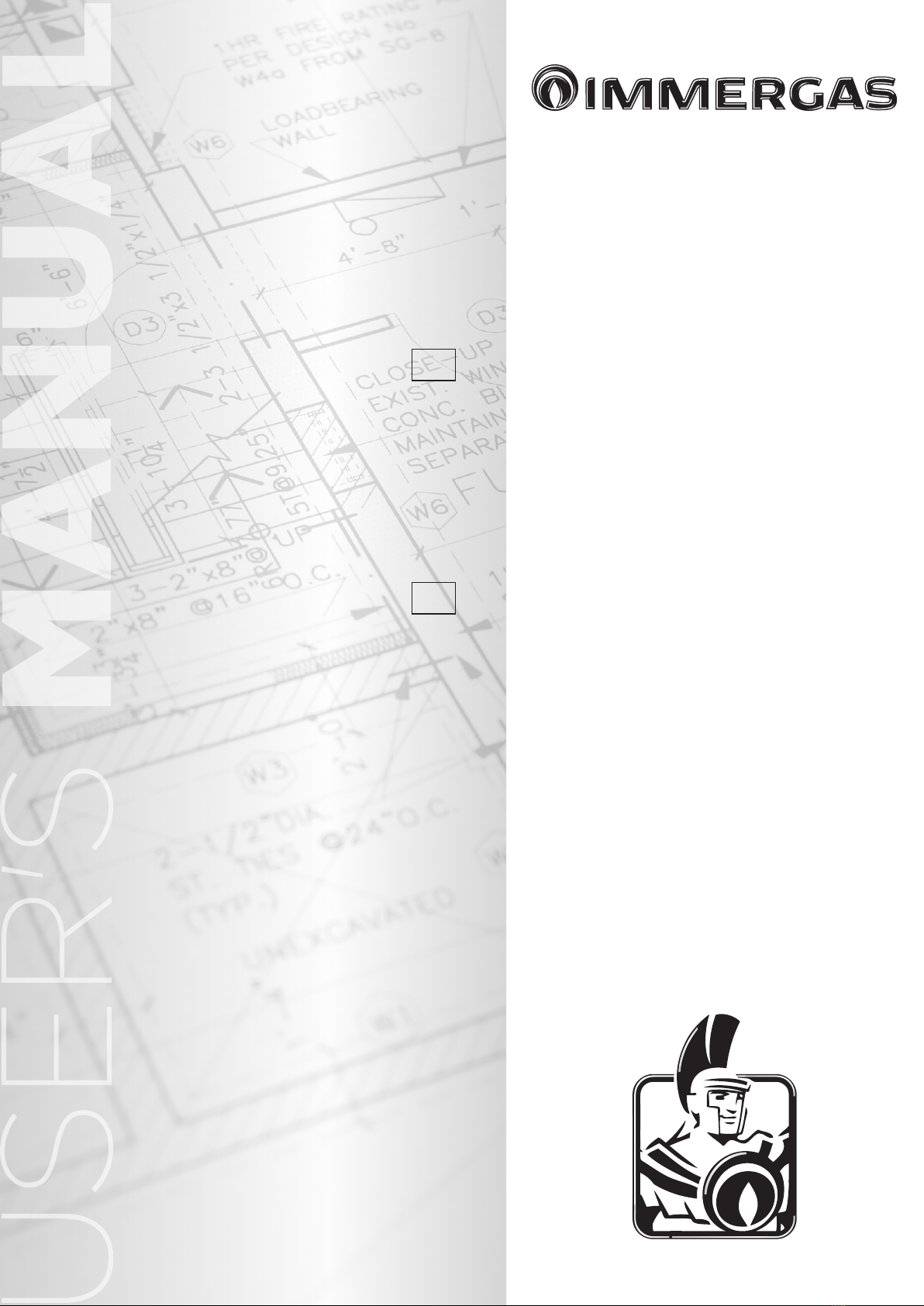
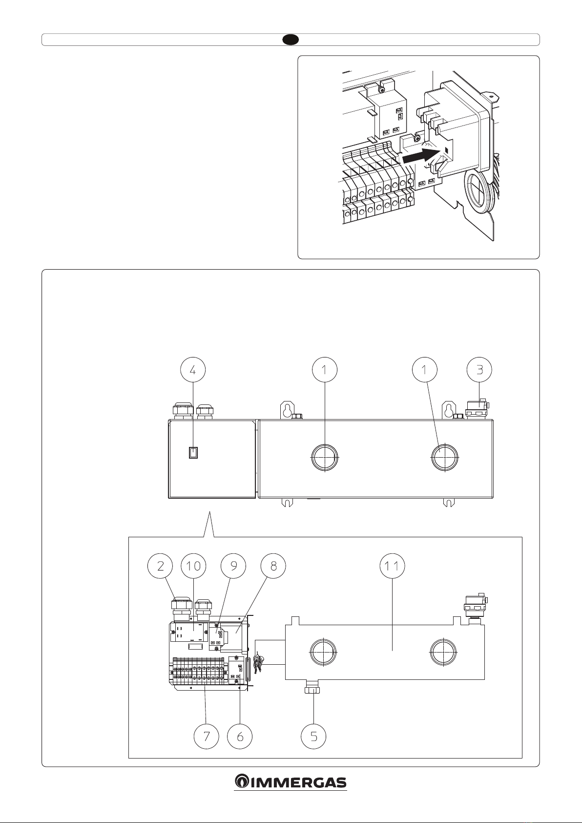
1.4 PRESENTAZIONE DEL PRODOTTO.
Il riscaldatore elettrico addizionale è stato appositamente proget-
tato per funzionare in associazione con una pompa di calore su un
impianto di riscaldamento in acqua pura o glicolata (40% max).
Comprende 3 stadi di potenza da 2 kW, 4 kW e 6 kW pilotati sepa-
ratamente con possibilità di cablaggio monofase o trifase.
Può essere utilizzato per il riscaldamento aggiuntivo in modo da
assicurare un complemento di potenza quando la domanda di
riscaldamento è superiore alla capacità della pompa di calore.
3

IT
2INSTALLAZIONE.
Il riscaldatore è stato appositamente progettato per essere installato
all’interno di edici domestici (atmosfera non esplosiva) in zone non
soggette a gelo. Tale apparecchio non è stagno alle proiezioni d’ac-
qua e non può essere installato in locali umidi del tipo lavanderia.
2.1 COLLEGAMENTI IDRAULICI.
Il riscaldatore deve essere installato sempre a valle della pompa di
calore (vedi pianta di montaggio Fig. 2). Non può funzionare senza
portata d’acqua (rischio di ebollizione). In caso di montaggio del
riscaldatore in un circuito diretto (portata d’acqua assicurata da
parte del circolatore della pompa di calore), la mancanza di portata
è controllata dalla pompa di calore. In caso di montaggio su circuito
di riscaldamento disaccoppiato, l’installatore vericherà il rispetto
della portata d’acqua.
In caso di inserimento di organi di interruzione idraulica (valvole,
…) tra la pompa di calore ed il riscaldatore, che serve ad isolare
idraulicamente questo ultima, si dovrà obbligatoriamente installare
una valvola di sicurezza (vedi schema di montaggio Fig. 2).
2.2 COLLEGAMENTI ELETTRICI.
L’alimentazione proviene da un interruttore automatico o da un
portafusibili fornito dall’installatore. Le caratteristiche dei fusibili
sono riportate nella tabella al Parag. 2.12 Dati tecnici.
L’impianto elettrico ed il cablaggio dell’unità devono essere conformi
alle norme in vigore nel paese d’installazione.
Attenzione: l’apparecchio deve essere collegato alla terra per evitare
gli eventuali pericoli causati da difetti di isolamento.
Attenzione: prima di richiudere il coperchio del riscaldatore, assi-
curarsi che il cavo di terra sia correttamente collegato.
2.3 AVVIO.
Riempire il circuito d’acqua e vericare l’assenza di perdite.
Spurgare tutto il circuito di riscaldamento e vericare che sia pre-
sente una portata d’acqua corretta prima di qualsiasi messa sotto
tensione delle resistenze.
Il riscaldatore è dotato di un doppio termostato di sicurezza: riarmo
automatico a 70°C e riarmo manuale a 83°C.
2.4 MODI DI FUNZIONAMENTO DA PARAMETRARE
SULLA POMPA DI CALORE.
Modo riscaldamento aggiuntivo.
Lo scopo è quello di mantenere il comfort delle persone presenti
nel locale quando la pompa di calore non è abbastanza potente
privilegiando il funzionamento della parte termodinamica al ne
di ottenere prestazioni ottimali.
Le resistenze sono attivate soltanto se la pompa di calore rileva una
mancanza di potenza della parte termodinamica (controllo della
temperatura dell’acqua).
Per la congurazione dell’intervento della resistenza integrativa far
riferimento alla documentazione della pompa di calore.
4

IT
1
2.5 DIMENSIONI PRINCIPALI.
5

IT
2
2.6 APERTURA CARTER ACCESSO MORSETTIERA.
Svitare la vite (1), togliere la rondella (2) e aprire frontalmente il carter (3) (Fig. 2).
3
2.7 CONVERSIONE ALIMENTAZIONE.
Per poter alimentare la resistenza con una tensione di 230 V 50 Hz monofase rispetto a 400 V 50 Hz trifase è necesasrio inserire il pettine
(1) come indicato in Fig. 3.
1
3
2
1
6

IT
Congurazione kit resistenza integrativa impianto per AUDAX.
Congurazione kit resistenza integrativa impianto TRIO V2 - TRIO MONO V2.
utilizzare il kit presente
nella confezione
utilizzare il kit presente
nella confezione
utilizzare il kit presente
nella confezione
utilizzare il kit presente
nella confezione
utilizzare il kit presente
nella confezione
utilizzare il kit presente
nella confezione
Alimentazione
230 Vac 50 Hz
Comando
a 21 V.
Comando
a 21 V.
Comando
a 21 V.
Comando
a 21 V.
Comando
a 21 V.
Comando
a 21 V.
Alimentazione
400 Vac + N
50 Hz
Alimentazione
400 Vac + N
50 Hz
Alimentazione
400 Vac + N
50 Hz
Alimentazione
230 Vac 50 Hz
Alimentazione
230 Vac 50 Hz
Congurazione Resistenza integrativa
2kW alimentata a 230 Vac 50 Hz
Congurazione Resistenza integrativa
2kW alimentata a 230 Vac 50 Hz
Congurazione Resistenza integrativa
2kW alimentata a 400 Vac + N 50 Hz
Congurazione Resistenza integrativa
2kW alimentata a 400 Vac + N 50 Hz
Congurazione Resistenza integrativa
4kW alimentata a 400 Vac + N 50 Hz
Congurazione Resistenza integrativa
4kW alimentata a 400 Vac + N 50 Hz
Congurazione Resistenza integrativa
6kW alimentata a 400 Vac + N 50 Hz
Congurazione Resistenza integrativa
6kW alimentata a 400 Vac + N 50 Hz
Congurazione Resistenza integrativa
4kW alimentata a 230 Vac 50 Hz
Congurazione Resistenza integrativa
4kW alimentata a 230 Vac 50 Hz
Congurazione Resistenza integrativa
6kW alimentata a 230 Vac 50 Hz
Congurazione Resistenza integrativa
6kW alimentata a 230 Vac 50 Hz
NOTA:
il relè KC3 è
incluso nel
kit
4
5
7

IT
Congurazione kit resistenza integrativa impianto per MAGIS M.
utilizzare il kit presente
nella confezione
utilizzare il kit presente
nella confezione
utilizzare il kit presente
nella confezione
Alimentazione
230 Vac 50 Hz
Alimentazione
400 Vac + N
50 Hz
Alimentazione
400 Vac + N
50 Hz
Alimentazione
400 Vac + N
50 Hz
Alimentazione
230 Vac 50 Hz
Alimentazione
230 Vac 50 Hz
Congurazione Resistenza integrativa
2kW alimentata a 230 Vac 50 Hz
Congurazione Resistenza integrativa
2kW alimentata a 400 Vac + N 50 Hz
Congurazione Resistenza integrativa
4kW alimentata a 400 Vac + N 50 Hz
Congurazione Resistenza integrativa
6kW alimentata a 400 Vac + N 50 Hz
Congurazione Resistenza integrativa
4kW alimentata a 230 Vac 50 Hz
Congurazione Resistenza integrativa
6kW alimentata a 230 Vac 50 Hz
6
8

IT
2.9 COMPONENTI PRINCIPALI.
Legenda:
1 - Ingresso/Uscita acqua 1”1/2 gas maschio (40x49) raccordo a guarnizione piatta
2 - Alimentazione elettrica
3 - Rubinetto di scarico
4 - Interruttore riscaldamento di emergenza
5 - Valvola di scarico Ø1/2» gas maschio (15x21)
6 - Relè KC3 per collegamento (solo pompa di calore AUDAX)
7 - Morsettiera
8 - Termostato di sicurezza
9 - Relè
10 - Relè
11 - Resistenza
2.8 RIARMO SICUREZZE.
Attenzione: il riscaldamento elettrico è dotato di 1 sicurezza con
due livelli d'intervento, una a riarmo automatico ed una a riarmo
manuale (Fig. 7), che tolgono alimentazione alle resistenze riscal-
danti non appena viene rilevata un’anomalia nel funzionamento
dell’apparecchio.
7
8
9

IT
Legenda:
BK - Nero
BN - Marrone
BU - Blu
GNYE - Verde / Giallo
GY - Grigio
OG - Arancione
RD - Rosso
VT - Viola
WH - Bianco
KC1 - Relè resistenze fase 1
KC2 - Relè resistenze fase 2
FCA - Protezione termica a riarmo automatico
FCM - Protezione termica a riarmo manuale
ICS - Interruttore abilitazione
HCS - Segnalazione abilitazione
R - Resistenze elettriche
2.10 SCHEMA ELETTRICO.
2.11 DATI TECNICI.
Riscaldatore 6 kW 6 kW
Alimentazione elettrica 230V - 50Hz monofase + terra 400V - 50Hz trifase + N + terra
Intensità totale max. 31.5A 10.5A
Protezione generale (non fornita) 32A 12A
Cavo d’alimentazione 3G6 5G1.5
Cavo di collegamento pompa di calore <=> kit 2G1 2G1
Potenza 3 x 2000 W - 230 V
Pressione massima di lavoro 3 bar
Temperatura di lavoro 65 °C
Temperatura massima 90 °C
Peso 8 kg
9
10

IE
e manufacturer declines all liability due to printing or transcription errors, reserving the right to make any modications to its
technical and commercial documents without forewarning.
INDEX
1 General recommendations. .......................................................... 12
1.1 Safety directions. ............................................................................ 12
1.2 Inspection and storage. ................................................................. 12
1.3 Warranty.......................................................................................... 12
1.4 Product presentation. .................................................................... 12
2 Installation. ..................................................................................... 13
2.1 Hydraulic connections. ................................................................. 13
2.2 Electrical connections. .................................................................. 13
2.3 Commissioning.............................................................................. 13
2.4 Operating modes (parameters to be set on the Heat Pump). .. 13
2.5 Main dimensions. .......................................................................... 14
2.6 Carter opening for terminal board access. ................................. 15
2.7 Supply Conversion......................................................................... 15
2.8 Reset safety device. ........................................................................ 18
2.9 Main components. ......................................................................... 18
2.10 Wiring diagram......................................................................... 19
2.11 Technical data. .......................................................................... 19
11

IE
1GENERAL
RECOMMENDATIONS.
Attention: power supply must be switched o before starting to
work in the electric control box!
Please read the following safety precautions very carefully before
installing the unit.
1.1 SAFETY DIRECTIONS.
Follow the safety rules in forces when you are working on your
appliance.
e installation, commissioning and maintenance of these units
should be performed by qualied personnel having a good knowl-
edge of standards and local regulations, as well as experience of
this type of equipment.
Any wiring produced on site must comply with the corresponding
national electrical regulations.
Make sure that the power supply and its frequency are adapted to the
required electric current of operation, taking into account specic
conditions of the location and the current required for any other
appliance connected with the same circuit.
e unit must be earthed to avoid any risks caused by insulation
defects.
It is forbidden to start any work on the electrical components if
water or high humidity is present on the installation site.
Warning:
When making the hydraulic connections, ensure that no impurities
are introduced into the pipe work.
e manufacturer declines any responsibility and the warrantly
becomes void if these instructions are not respected.
If you meet a problem, please call the Technical Department of
your area.
e information contained in these Instructions are subject to
modication without advance notice.
1.2 INSPECTION AND STORAGE.
At the time of receiving the equipment carefully cross check all the
elements against the shipping documents in order to ensure that all
the crates and boxes have been received. Inspect the unit for any
visible or hidden damage.
In the event of shipping damage, write precise details of the
damage on the shipper’s delivery note and send immediately a
registered letter to the shipper within 48 hours, clearly stating the
damage caused. Forward a copy of this letter to the manufacturer
or his representative.
e unit must be stored indoors, completely protected from rain,
snow etc. e unit must not be damaged by changes in the weather
(high and low temperatures). Excessively high temperatures (above
60 °C) can harm certain plastic materials and cause permanent dam-
age. Moreover, the performance of certain electrical or electronic
components can be impaired.
1.3 WARRANTY.
Any modication to the unit without the manufacturer’s prior
approval, shall automatically render the warranty null and void.
e following conditions must be respected in order to maintain
the validity of the warranty:
• Commissioning shall be performed by specialised technicians.
• Maintenance shall be performed by technicians trained for this
purpose.
• Only Original equipment spare parts shall be used.
• all the operations listed in the present manual shall be performed
within the prescribed schedule.
Attention: the warranty shall be null and void in the event of non-
compliance with any of the above conditions.
1.4 PRODUCT PRESENTATION.
is additional electric heater has been designed to operate
in association with a PAC in a clear water or glycol mixture
(40% maximum) water heating system. It oers three heating capaci-
ties of 2kW, 4kW and 6kW that are controlled independently and it
oers the possibility of single phase and three phase connections.
It can be used to provide additional heating capacity when the de-
mand for heating exceeds the capacity supplied by the Heat Pump.
12

IE
2INSTALLATION.
e heater has been designed for indoor installation in the home in
an explosion risk-free area and, if possible, protected from sub-zero
temperatures. is device is not sealed against water splashes and
must not be installed in damp surroundings, such as wash houses
or laundry rooms.
2.1 HYDRAULIC CONNECTIONS.
e heater must be installed in a position, always downstream of the
PAC (refer to assembly layout drawing, Fig. 2). It will not operate
without a water supply, (risk of boiling). If the heater is installed
directly in the water circuit (water ow guaranteed by the PAC cir-
culation pump), the PAC system controls the risk of low water ow.
If the heater is installed in a separate heating circuit, the installer
must ensure that an adequate water ow is guaranteed.
If water cut-o devices, such as valves, are installed between the
PAC and the heater, meaning that it can be hydraulically isolated,
a safety valve must be also installed. (Refer to assembly layout
drawing, Fig. 2).
2.2 ELECTRICAL CONNECTIONS.
e power supply must pass through a circuit breaker or fuse holder
provided by the installer. fuse sizes are indicated in the table in
Parag. 2.12 Technical Data.
the electrical installation and wiring of the heater must comply with
current regulations in the country of installation.
Attention: the appliance must be earthed to avoid any possible
danger caused by faulty insulation.
Attention: make sure that the ground cable is connected properly
before closing the heater cover.
2.3 COMMISSIONING.
Fill the circuit water and check that it is fully watertight.
Bleed the entire heating circuit and check that an adequate water
ow is present before switching on the heating resistances.
is heater is equipped with a dual safety thermostat: automatic
reset at 70° C and manual reset at 83° C.
2.4 OPERATING MODES PARAMETERS TO BE SET ON
THE HEAT PUMP.
Boost mode.
e aim is to maintain occupier comfort when the Heat Pump lacks
sucient power, while favouring operation of the thermodynamic
section for optimal performance.
e resistances are only activated if the Heat Pump detects a lack
of capacity from the thermodynamic section (via measurement of
water temperature).
To congure the intervention of the supplementary heater refer to
the heat pump documentation.
13

IE
2.5 MAIN DIMENSIONS.
1
14

IE
2.6 CARTER OPENING FOR TERMINAL BOARD ACCESS.
Unscrew the screw (1), remove the washer (2) and open the carter (3) head-on (Fig. 2).
2.7 SUPPLY CONVERSION.
In order to supply a 230 V 50 Hz single-phase voltage to the resistance, compared to a 400 V 50 Hz three-phase supply, it is necessary to
introduce the comb (1) as indicated in Fig. 3.
2
3
2
1
3
1
15

IE
400 Vac + N
50 Hz
Supply
System supplementary resistance kit conguration for AUDAX.
System supplementary resistance kit conguration for TRIO V2 - TRIO MONO V2.
use the kit in
the package
use the kit in
the package
use the kit in
the package
230 Vac 50 Hz
Supply
21 V.
control
21 V.
control
21 V.
control
21 V.
control
21 V.
control
21 V.
control
230 Vac 50 Hz
Supply
230 Vac 50 Hz
Supply
Supplementary Resistance conguration
2kW supplied with 230 Vac 50 Hz
Supplementary Resistance conguration
2kW supplied with 230 Vac 50 Hz
Supplementary Resistance conguration
2kW supplied with 400 Vac + N 50 Hz
Supplementary Resistance conguration
2kW supplied with 400 Vac + N 50 Hz
Supplementary Resistance conguration
4kW supplied with 400 Vac + N 50 Hz
Supplementary Resistance conguration
4kW supplied with 400 Vac + N 50 Hz
Supplementary Resistance conguration
6kW supplied with 400 Vac + N 50 Hz
Supplementary Resistance conguration
6kW supplied with 400 Vac + N 50 Hz
Supplementary Resistance conguration
4kW supplied with 230 Vac 50 Hz
Supplementary Resistance conguration
4kW supplied with 230 Vac 50 Hz
Supplementary Resistance conguration
6kW supplied with 230 Vac 50 Hz
Supplementary Resistance conguration
6kW supplied with 230 Vac 50 Hz
400 Vac + N
50 Hz
Supply
400 Vac + N
50 Hz
Supply
NOTE:
the KC3 relay
is included in
the kit
use the kit in
the package
use the kit in
the package
use the kit in
the package
4
5
16

IE
400 Vac + N
50 Hz
Supply
System supplementary resistance kit conguration for MAGIS M.
use the kit in
the package
use the kit in
the package
use the kit in
the package
230 Vac 50 Hz
Supply
230 Vac 50 Hz
Supply
230 Vac 50 Hz
Supply
Supplementary Resistance conguration
2kW supplied with 230 Vac 50 Hz
Supplementary Resistance conguration
2kW supplied with 400 Vac + N 50 Hz
Supplementary Resistance conguration
4kW supplied with 400 Vac + N 50 Hz
Supplementary Resistance conguration
6kW supplied with 400 Vac + N 50 Hz
Supplementary Resistance conguration
4kW supplied with 230 Vac 50 Hz
Supplementary Resistance conguration
6kW supplied with 230 Vac 50 Hz
400 Vac + N
50 Hz
Supply
400 Vac + N
50 Hz
Supply
6
17

IE
2.8 RESET SAFETY DEVICE.
Attention: e electric heating system is equipped with 1 safety
device (Fig. 7). It cuts o electrical supply to the heating resistances
as soon as an operating anomaly is detected.
7
8
Key:
1 - Water inlet/outlet 1»1/2 male gas (40x49) at joint connection
2 - Mains power supply
3 - Bleed
4 - Backup heater operating switch
5 - Drain Ø1/2» male gas (15x21)
6 - Relay for connection (AUDAX heat pump only)
7 - Terminal board
8 - Safety thermostat
9 - Relay
10 - Relay
11 - Resistance
2.9 MAIN COMPONENTS.
18

IE
Legend:
BK - Black
BN - Brown
BU - Blue
GNYE - Green / Yellow
GY - Grey
OG - Orange
RD - Red
VT - Violet
WH - White
KC1 - Heater stage 1 relay
KC2 - Heater stage 2 relay
FCA - High temperature automatic reset cut-cut
FCM - High temperature manual reset cut-cut
ICS - enable switch
HCS - operating light
R - electric heater
2.10 WIRING DIAGRAM.
2.11 TECHNICAL DATA.
Heater 6 KW 6KW
Electric supply
230V - 50Hz single phase +
ground
400V - 50Hz three phase + N +
ground
Max. total intensity 31.5A 10.5A
General protection (not supplied) 32A 12A
Supply cable 3G6 5G1.5
Heat pump <=> kit connection cable 2G1 2G1
Power 3x2000 W - 230 V
Max. working pressure 3 bar
Working temperature 65 °C
Max. temperature 90 °C
Weight 8 kg
9
19

Nel corso della vita utile dei prodotti, le prestazioni sono
inuenzate da fattori esterni, come ad es. la durezza dell'acqua
sanitaria, gli agenti atmosferici, le incrostazioni nell'impianto
e così via. I dati dichiarati si riferiscono ai prodotti nuovi e
correttamente installati ed utilizzati, nel rispetto delle norme
vigenti.
N.B.: si raccomanda di fare eseguire una corretta
manutenzione periodica.
During the useful life of the products, performance is aected
by external factors, e.g. the hardness of the DHW, atmospheric
agents, deposits in the system and so on. e data declared
refer to new products that are correctly installed and used with
respect to the Standards in force.
N.B.: correct periodic maintenance is highly recommended.
Immergas TOOLBOX
L’App studiata da Immergas per i professionisti
The App designed by Immergas for professionials
Disponibile su Disponibile su Disponibile su
immergas.com
Per richiedere ulteriori approfondimenti specici, i Professionisti
del settore possono anche avvalersi dell’indirizzo e-mail:
To request further specic details, sector Professionals can also
Immergas S.p.A.
42041 Brescello (RE) - Italy
Tel. 0522.689011
Fax 0522.680617
Il libretto istruzioni è realizzato in carta ecologica
is instruction booklet is madeof ecological paper.
Cod. 1.039122 - rev. ST.002091/004 - 08/22
Table of contents
Languages:
Popular Electric Heater manuals by other brands

Fanmaster
Fanmaster PESH30 instruction manual

Dimplex
Dimplex WFC 3NS operating instructions

Harvia
Harvia BX90 Instructions for installation and use

Dimplex
Dimplex BUH19BWS Installation and operating instructions

Trotec
Trotec IR2005 SC operating manual

Airchaud Diffusion
Airchaud Diffusion Haverland HL WI3S/C Instruction and installation manual