manuals.online logo
Brands
  1. Home
  2. •
  3. Brands
  4. •
  5. Immergas
  6. •
  7. Heat Pump
  8. •
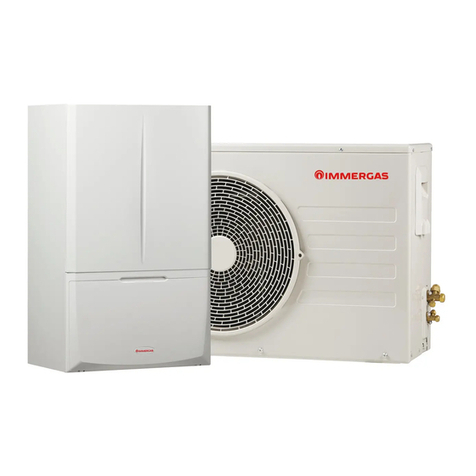
  9. Immergas MAGIS M 4 Product manual

Immergas MAGIS M 4 Product manual

This manual suits for next models

25

Other Immergas Heat Pump manuals

Immergas MAGIS COMBO PLUS Series Product manual

Immergas

Immergas MAGIS COMBO PLUS Series Product manual

Immergas MAGIS COMBO PLUS 5 Product manual

Immergas

Immergas MAGIS COMBO PLUS 5 Product manual

Immergas AUDAX PRO 4 V2 Product manual

Immergas

Immergas AUDAX PRO 4 V2 Product manual

Immergas MAGIS PRO Series Operating instructions

Immergas

Immergas MAGIS PRO Series Operating instructions

Immergas MAGIS HERCULES PRO 4 Operating instructions

Immergas

Immergas MAGIS HERCULES PRO 4 Operating instructions

Immergas MAGIS PRO 4 V2 Operating instructions

Immergas

Immergas MAGIS PRO 4 V2 Operating instructions

Immergas AUDAX PRO 4 V2 Product manual

Immergas

Immergas AUDAX PRO 4 V2 Product manual

Immergas MAGIS COMBO PLUS V2 Series Operating instructions

Immergas

Immergas MAGIS COMBO PLUS V2 Series Operating instructions

Immergas AUDAX TOP 6 ErP Operating instructions

Immergas

Immergas AUDAX TOP 6 ErP Operating instructions

Immergas 3.023355 User manual

Immergas

Immergas 3.023355 User manual

Immergas MAGIS M4-30 Technical manual

Immergas

Immergas MAGIS M4-30 Technical manual

Immergas Magis Combo 5 Product manual

Immergas

Immergas Magis Combo 5 Product manual

Immergas MAGIS COMBO Product manual

Immergas

Immergas MAGIS COMBO Product manual

Immergas Trio Base V2 User manual

Immergas

Immergas Trio Base V2 User manual

Immergas IMMERWATER 190S V5 Product manual

Immergas

Immergas IMMERWATER 190S V5 Product manual

Immergas AUDAX PRO 5 Product manual

Immergas

Immergas AUDAX PRO 5 Product manual

Immergas MAGIC COMBO PLUS Series Product manual

Immergas

Immergas MAGIC COMBO PLUS Series Product manual

Immergas MAGIS HERCULES PRO MINI 6 Operating instructions

Immergas

Immergas MAGIS HERCULES PRO MINI 6 Operating instructions

Immergas AUDAX PRO 5 Operating instructions

Immergas

Immergas AUDAX PRO 5 Operating instructions

Immergas MAGIS COMBO 4 V2 Operating instructions
Immergas

Immergas MAGIS COMBO 4 V2 Operating instructions

Immergas TRIO PACK HYBRID 4 Product manual

Immergas

Immergas TRIO PACK HYBRID 4 Product manual

Immergas HYDRO 3 Product manual

Immergas

Immergas HYDRO 3 Product manual

Immergas 3.023355 User manual

Immergas

Immergas 3.023355 User manual

Immergas TRIO PACK ELECTRIC 4 Product manual

Immergas

Immergas TRIO PACK ELECTRIC 4 Product manual

Popular Heat Pump manuals by other brands

Daikin RXL12QMVJU Service manual

Daikin

Daikin RXL12QMVJU Service manual

AIREDALE BluCube CUR092V16-1CO-0 Installation and maintenance manual

AIREDALE

AIREDALE BluCube CUR092V16-1CO-0 Installation and maintenance manual

Calyenty RBH 125 Customer's manual

Calyenty

Calyenty RBH 125 Customer's manual

GRE HPGI50 owner's manual

GRE

GRE HPGI50 owner's manual

Carrier 30XW Installation, operation and maintenance instructions

Carrier

Carrier 30XW Installation, operation and maintenance instructions

Hayward SUMHEAT HP5131DT3 Installation instructions manual

Hayward

Hayward SUMHEAT HP5131DT3 Installation instructions manual

REMKO SQW 400 Electrical wiring

REMKO

REMKO SQW 400 Electrical wiring

Sanyo SAP120FCH Service manual

Sanyo

Sanyo SAP120FCH Service manual

Daikin EHYHBH05AA Operation manual

Daikin

Daikin EHYHBH05AA Operation manual

Panasonic WH-SDF03E3E5 Design handbook

Panasonic

Panasonic WH-SDF03E3E5 Design handbook

Airxcel 45000 Series Installation, operation and maintenance instructions

Airxcel

Airxcel 45000 Series Installation, operation and maintenance instructions

Mitsubishi Electric PUZ-SWM60VAA Service manual

Mitsubishi Electric

Mitsubishi Electric PUZ-SWM60VAA Service manual

Dimplex LI 16I-TUR Installation and operating instruction

Dimplex

Dimplex LI 16I-TUR Installation and operating instruction

Carrier WSHP Open v3 Integration guide

Carrier

Carrier WSHP Open v3 Integration guide

Mitsubishi Electric EHSE-YM9EC Service manual

Mitsubishi Electric

Mitsubishi Electric EHSE-YM9EC Service manual

TGM CTV14CN018A Technical manual

TGM

TGM CTV14CN018A Technical manual

Carrier 38MGQ Series installation instructions

Carrier

Carrier 38MGQ Series installation instructions

Kokido K2O K880BX/EU Owner's manual & installation guide

Kokido

Kokido K2O K880BX/EU Owner's manual & installation guide

manuals.online logo
manuals.online logoBrands
  • About & Mission
  • Contact us
  • Privacy Policy
  • Terms and Conditions

Copyright 2025 Manuals.Online. All Rights Reserved.

MAGIS
M4-30
Block heat pumps
Control Panel
IE
Instructions and warnings
*1.046979ENG*
*1.046979ENG*
Dear Customer,
Congratulations for having chosen a top-quality Immergas product, able to assure well-being and safety for a long period of
time.AsanImmergascustomeryoucanalsocountonaQualiedAuthorisedAer-SalesTechnicalAssistanceCentre,prepared
andupdatedtoguaranteeconstanteciencyof yourappliance.Readthefollowingpagescarefully:youwillbeable todrawuse-
fultipsontheproperuseofthedevice,compliancewithwhichwillconrmyoursatisfactionwiththeImmergasproduct.
For assistance and routine maintenance, contact Authorised Technical Service Centres: they have original spare parts and are
specicallytraineddirectlybythemanufacturer.
General warnings
All Immergas products are protected with suitable transport packaging.
e material must be stored in a dry place protected from the weather.
e instruction booklet is an integral and essential part of the product and must be given to the new user in the case of transfer
or succession of ownership.
It must be stored with care and consulted carefully, as all of the warnings provide important safety indications for installation,
use and maintenance stages.
is instruction manual provides technical information for installing the Immergas pack. As for the other issues related to pack
installation (e.g. safety in the work site, environment protection, injury prevention), it is necessary to comply with the provisions
specied in the regulations in force and good practice rules.
In compliance with legislation in force, the systems must be designed by qualied professionals, within the dimensional limits
established by the Law. Installation and maintenance must be performed in compliance with the regulations in force, according
to the manufacturer's instructions and by professionally qualied sta, intended as sta with specic technical skills in the
system sector, as envisioned by the Law.
Improper installation or assembly of the Immergas appliance and/or components, accessories, kits and devices can cause
unexpected problems for people, animals and objects. Read the instructions provided with the product carefully to ensure
proper installation.
Maintenance must be carried out by skilled technical sta. e Authorised Aer-Sales Service represents a guarantee in terms
of qualications and professionalism.
e appliance must only be destined for the use for which it has been expressly declared. Any other use will be considered
improper and therefore potentially dangerous.
If errors occur during installation, operation and maintenance, due to non-compliance with technical laws in force, standards
or instructions contained in this book (or however supplied by the manufacturer), the manufacturer is excluded from any
contractual and extra-contractual liability for any damage and the appliance warranty is invalidated.
e company IMMERGAS S.p.A., with registered oce in via Cisa Ligure 95 42041 Brescello (RE), declares that the design,
manufacturing and aer-sales assistance processes comply with the requirements of standard UNI EN ISO 9001:2015.
For further details on the product CE marking, request a copy of the Declaration of Conformity from the manufacturer,
specifying the appliance model and the language of the country.
e manufacturer declines all liability due to printing or transcription errors, reserving the right to make any modications
to its technical and commercial documents without forewarning.
INDEX
1 General safety warnings. .........................................................................................................................................5
1.1 About the documentation......................................................................................................................................................... 5
1.2 For the user. ................................................................................................................................................................................ 5
2 Presentation of Control panel................................................................................................................................. 6
2.1 Appearance of the Control panel............................................................................................................................................. 6
2.2 Status icons. ................................................................................................................................................................................ 7
3 Using home pages. ...................................................................................................................................................9
4 Menu structure. ..................................................................................................................................................... 12
4.1 About the menu structure....................................................................................................................................................... 12
4.2 Access to the menu structure. ................................................................................................................................................ 12
4.3 How to navigate in the menu structure................................................................................................................................. 12
5 Basic use................................................................................................................................................................. 13
5.1 Screen unlock. .......................................................................................................................................................................... 13
5.2 Switching controls on/o........................................................................................................................................................ 14
5.3 Adjusting the temperature...................................................................................................................................................... 17
5.4 Adjusting space operation mode. .......................................................................................................................................... 18
6 Operation............................................................................................................................................................... 20
6.1 Operation mode....................................................................................................................................................................... 20
6.2 Preset temperature................................................................................................................................................................... 20
6.3 Domestic Hot Water (DHW). ................................................................................................................................................ 24
6.4 Schedule. ................................................................................................................................................................................... 29
6.5 Options...................................................................................................................................................................................... 33
6.6 Child lock.................................................................................................................................................................................. 37
6.7 Service information. ................................................................................................................................................................ 39
6.8 Operation parameters. ............................................................................................................................................................ 41
6.9 For Serviceman. ....................................................................................................................................................................... 43
6.10SN VIEW .................................................................................................................................................................................. 44
7 Menu structure: overview. ..................................................................................................................................... 45
• is manual provides a detailed explanation on the precautions to be taken during use.
• Read this manual carefully before using the wall-mounted control unit to guarantee its proper operation.
• Aer you have read this manual, keep it for future consultation.
5
1GENERAL SAFETY WARNINGS.
1.1 ABOUT THE DOCUMENTATION.
• e precautions described in this document cover very important topics. Follow them carefully
DANGER
Indicates a situation that could result in serious injury or death.
DANGER:
RISK OF ELECTROCUTION
Indicates a situation that could result in electrocution.
DANGER:
RISK OF BURNING
Indicates a situation that could result in burns because of extreme hot or cold temperatures.
WARNING
Indicates a situation that could result in serious injury or death.
CAUTION
Indicates a situation that could result in minor or moderate injury.
NOTE
Indicates a situation that could result in equipment or property damage.
iINFORMATION
Indicates useful tips or additional information.
1.2 FOR THE USER.
• If you are not sure how to operate the unit, contact your installer.
• is appliance must not be used by persons (including children) without adequate physical, sensory or mental capacities
or without specic experience and knowledge, unless they are supervised or have been instructed as to how to use the
appliance by a person responsible for their safety. Supervise children and make sure they do not play with the device.
CAUTION
Do NOT wash the unit as this could result in electrocution or re.
• e devices are marked with the following symbol:
is symbol indicates that electric and electronic products must not be disposed of together with household unsorted
waste. Do NOT try to disassemble the system on your own: only a qualied installer may disassemble the device and
process the refrigerant, oil and other components, in compliance with standards in force. e units must be processed at
a specic waste disposal facility so that the materials can be reused, recycled and recovered. Making sure that the product
is disposed of correctly shall avoid possible negative consequences for the environment and human health. For further
information, contact your installer or local authorities.
• Install in a place where there is no radiation present.
6
2PRESENTATION OF CONTROL PANEL.
2.1 APPEARANCE OF THE CONTROL PANEL.
1
2
3
4
5
6
Reference Icon Function
1Enter the menu structure from the home page.
2
Move the cursor on the display.
Navigate in the menu structure.
Adjust the settings.
3Go back to higher level.
4
Go to the next step when programming a schedule in the menu structure.
Conrm a selection.
Enter a submenu in the menu structure.
5Long press to unlock/lock the control panel.
6Enable or disable the space operation mode or DHW mode.
Enable or disable the function in the menu structure.
7
2.2 STATUS ICONS.
1
2
3
4
5
6
7
8
9
10
11
12
13
14
15
16
Reference Icon Description
1Lock icon
2
Desired temperature does not change
At the next scheduled action, the
desired temperature will decrease
Desired temperature decreases
Desired temperature increases
3
Fan coil on
Radiator on
Floor heating on
4
Desired water ow temperature
Desired room temperature
5
Heat mode
Cool mode
Auto mode
6
Additional heating source
Electric pipe heating source
7Compressor on
8
Reference Icon Description
8
Anti-freeze mode activated
Defrost mode activated
Holiday away / home activated
Silent mode activated
ECO mode activated
9
Error or protection icon
Pump I on
Smart grid
Free electricity
Peak end electricity
Peak electricity
10
Additional heating source
Solar energy activated
Tank heater on
11 Domestic hot water tank temperature
12
OFF
ON
Turn O / On
13 Disinfect function activated
14 Domestic hot water
15 External room temperature
16
7
Weekly schedule icon
Timer Icon
Fan coil Radiator Floor heating Domestic hot water
ON
OFF
9
3USING HOME PAGES.
When the control panel is switched on, the language selection page is displayed. Choose the desired language and then press
to view the home pages. If you do not press within 60 seconds, the system will set the currently selected language:
FR IT ES PL PTEN
OK
GE NL RO RU TR GR
e home pages can be used to read and adjust settings intended for daily use. e settings displayed and that can be set
on the home pages are described in the relative sections. e following home pages can be displayed depending on the
system layout:
• Desired room temperature (ROOM);
• Desired water ow temperature (MAIN);
• Actual domestic hot water tank temperature (TANK).
Home page 1.
If WATER FLOW TEMP. is set at YES and ROOM TEMP. is set at NO (see “FOR SERVICEMAN”>“TEMP. TYPE SET-
TING”in the Use and Installation Booklet”), the system will also include the oor heating and domestic hot water function.
Home page 1 will appear:
Schema dell'impianto 1
VS1
UI
CRP1CRP2...CRPn
Temperatura flusso dell'acqua desiderata
Desired water ow temperature
System layout 1
NOTE:
All the images in the manual have been inserted for illustrative purposes. erefore there could be dierences compared
to the pages that actually appear on the screen.
10
Home page 2.
If WATER FLOW TEMP. is set at NO and ROOM TEMP. is set at YES (see “FOR SERVICEMAN”>“TEMP. TYPE SET-
TING”in the Use and Installation Booklet”), the system will also include the oor heating and domestic hot water function.
Home page 2 will appear:
Schema dell'impianto 2
VS1
CRP1CRP2...CRPn
UI
Temperatura ambiente desiderata
Desired room temperature
System layout 2
NOTE:
e wall-mounted control panel should be installed in the oor heating room to be able to control the room temperature.
Home page 3.
If DHW MODE is set at NO (see “FOR SERVICEMAN”>“DHW MODE SETTING”in Use and Installation Booklet”)
and if WATER FLOW TEMP. is set at NO, ROOM TEMP. is set at YES (see “FOR SERVICEMAN”>“TEMP. TYPE SET-
TING”in Use and Installation Booklet”). ere will be a main page and an additional page. e system also has the function
including oor heating and space heating for fan coil. Home page 3 will appear:
Schema dell'impianto 3
Pagina principale
Pagina aggiuntiva
2
Temperatura flusso acqua desiderata zona 1
Temperatura ambiente desiderata zona 2
SV2
UI
FHL1 FHL2...FHLn
FCU1 FCU2...FCUn
Main page
Additional page
Zone 1 desired water ow temperature
Zone 2 desired room temperature
System layout 3