manuals.online logo
Brands
  1. Home
  2. •
  3. Brands
  4. •
  5. Immergas
  6. •
  7. Heat Pump
  8. •
  9. Immergas MAGIS COMBO 4 V2 Operating instructions

Immergas MAGIS COMBO 4 V2 Operating instructions

Instructionsandrecommendations
Installer
User
Maintenancetechnician
*1.045257ENG*

IE MAGISCOMBO
469V2
2
3
INDEX
Dear Customer.................................................................................. 4
General Recommendations............................................................. 5
Safety symbols used.......................................................................... 6
Personal protective equipment ....................................................... 6
1 Installing the indoor unit............................................... 7
1.1 Description of the product.................................................... 7
1.2 Installation warnings.............................................................. 7
1.3 Main dimensions.................................................................. 11
1.4 Minimum installation distances......................................... 11
1.5 Antifreeze protection ........................................................... 12
1.6 Indoor unit connection unit ............................................... 13
1.7 Hydraulic connection .......................................................... 13
1.8 Connecting the chiller line.................................................. 14
1.9 Electrical connection ........................................................... 15
1.10 Room chrono-thermostats (Optional) .............................. 18
1.11 MODBUS temperature and humidity room probes
(Optional).............................................................................. 18
1.12 Remote zone control (Optional) ........................................ 19
1.13 Dominus (Optional) ............................................................ 19
1.14 Humidistat ON/OFF (Optional) ........................................ 19
1.15 External temperature probe (Optional) ............................ 19
1.16 Temperature control setting................................................ 20
1.17 Immergas ue systems......................................................... 21
1.18 Tables of resistance factors and equivalent lengths of
“Green Range” ue system components............................ 23
1.19 Outdoor installation in partially protected area............... 25
1.20 Concentric horizontal kit installation................................ 27
1.21 Concentric vertical kit installation..................................... 28
1.22 Separator kit installation ..................................................... 30
1.23 C9 adaptor kit installation................................................... 31
1.24 Ducting of ues or technical slots...................................... 33
1.25 Conguration type B, open chamber and fan assisted
for indoors............................................................................. 33
1.26 Flue exhaust to ue/chimney. ............................................. 34
1.27 Flues, chimneys and chimney caps. ................................... 34
1.28 Water treatment plant lling............................................... 35
1.29 System lling......................................................................... 36
1.30 Filling the condensate drain trap........................................ 36
1.31 Gas system start-up. ............................................................. 36
1.32 Operating limits.................................................................... 36
1.33 Commissioning the indoor unit (Ignition, only when
paired with an outdoor unit) .............................................. 37
1.34 Circulation pump ................................................................. 38
1.35 Kits available on request ...................................................... 39
1.36 Main components................................................................. 40
2 Instructions for use and maintenance ......................... 41
2.1 General recommendations.................................................. 41
2.2 Control panel ........................................................................ 43
2.3 System use ............................................................................. 44
2.4 Fault and anomaly signals ................................................... 47
2.5 Parameters and information menu .................................... 56
2.6 Indoor unit shutdown.......................................................... 60
2.7 Restore central heating system pressure............................ 60
2.8 Draining the system ............................................................. 60
2.9 Emptying the D.H.W. circuit............................................... 60
2.10 Antifreeze protection ........................................................... 60
2.11 Cleaning the case.................................................................. 60
2.12 Permanent shutdown........................................................... 60
2.13 Use of the remote zone panel (Optional) .......................... 60
3 Instructions for maintenance and initial check...........61
3.1 General recommendations.................................................. 61
3.2 Initial check........................................................................... 61
3.3 Yearly appliance check and maintenance .......................... 62
3.4 Hydraulic diagram................................................................ 64
3.5 Wiring diagram..................................................................... 65
3.6 System lter........................................................................... 71
3.7 Troubleshooting.................................................................... 72
3.8 Gas valve................................................................................ 73
3.9 Converting the heat generator to other types of gas........ 73
3.10 Fan speed calibration ........................................................... 73
3.11 Adjustment of the air-gas ratio........................................... 74
3.12 P.C.B. programming............................................................. 75
3.13 "Chimney sweep” function.................................................. 82
3.14 Pump anti-block function................................................... 82
3.15 ree-way anti-block system .............................................. 82
3.16 Radiators antifreeze function.............................................. 82
3.17 Photovoltaic function........................................................... 82
3.18 Outdoor unit disable function............................................ 82
3.19 Preheating function.............................................................. 82
3.20 Diverter valve management (summer / winter)............... 82
3.21 Automatic venting function................................................ 82
3.22 Screed heater function......................................................... 83
3.23 Solar panels coupling function ........................................... 83
3.24 Dehumidication function ................................................. 84
3.25 Outdoor Unit Testmode Function ..................................... 84
3.26 Outdoor Unit Pump Down Function................................ 84
3.27 Puer in preheating function.............................................. 84
3.28 Night mode function............................................................ 84
3.29 System setpoint correction function.................................. 84
3.30 Generator management....................................................... 85
3.31 Casing removal ..................................................................... 86
4 Technical data............................................................... 88
4.1 Variable heat output ............................................................. 88
4.2 Magis Combo 4 V2 product che (in compliance with
Regulation 811/2013)........................................................... 90
4.3 Magis Combo 6 V2 product che (in compliance with
Regulation 811/2013)........................................................... 92
4.4 Magis Combo 9 V2 product che (in compliance with
Regulation 811/2013)........................................................... 94
4.5 Parameters for lling in the package che ........................ 96
4
DearCustomer
Congratulations forhavingchosena top-quality Immergas product, ableto assure well-being and safety for a long period of time.AsanIm-
mergascustomeryoucan alsocount ona Qualied AuthorisedAer-SalesTechnicalAssistanceCentre,prepared andupdated toguarantee
con stant ecienc y of your appliance. Read the following pages caref ully: you w ill be able to draw useful tips on the proper use of the device,
co m pl i an c e w i t h wh i c h w i l l c o n  r m yo u r sa t i s f a c ti o n w it h th e Im m e r g a s p ro d u c t .
For assistance and routine maintenance, contact Authorised Technical Service Centres: they have original spare parts and are specically
traineddirectlyby themanufacturer.
ermal systems must undergo periodic maintenance and scheduled checks of the energy eciency in compliance with national,
regionalor localprovisionsin force.
e company IMMERGASS.p.A., with registered oce in via Cisa Ligure 95 42041 Brescello (RE), declares that the design, manufac-
turing and aer-sales assistanceprocesses complywith therequirements ofstandard UNIENISO9001:2015.
For further details on the product CE marking, request a copy of the Declaration of Conformity from the manufacturer, specifying the
appliance model andthe languageofthe country.
e manufacturer declines all liability due to printing or transcription errors, reserving the right to make any modications to its tech-
nicalandcommercial documents withoutforewarning.
5
GENERALRECOMMENDATIONS
isbook contains importantinformationforthe:
Installer(section 1);
User (section 2);
MaintenanceTechnician(section 3).
• eusermust carefully readthe instructionsin thespecic section (section2).
• eusermust limit operationsontheappliance only tothose explicitlyallowed in thespecic section.
• Every operation carried out on the heat pump (e.g. set up, inspection, installation and commissioning), must mandatorily be
performedbyauthorisedpersonnelaloneandin possession ofatechnicalengineeringorprofessionaldegreequalifyingthemto
perform these tasks. ey must also have attended a refresher course acknowledged by competent authorities. is particularly
applies topersonal specialisedinC.H.and air-conditioningsystemsandqualiedelectricians who,duetotheir specialisedtrai-
ning, skills and experience are experts in the correct installation and maintenance of C.H., cooling and air-conditioning sy-
stems.
• eappliancemust beinstalled byqualied and professionallytrainedpersonnel.
• e instruction booklet is an integral and essential part of the product and must be given to the new user in the case of transfer or suc-
cession of ownership.
• Itmustbe storedwithcareandconsultedcarefully,as all ofthewarnings provide importantsafety indicationsforinstallation, useand
maintenance stages.
• In compliance with the legislation in force, the systems must be designed by qualied professionals, within the dimensional limits
established by theLaw.Installationandmaintenancemustbeperformed in compliancewith theregulationsin force,according tothe
manufacturer'sinstructionsandbyprofessionally qualiedsta,meaning sta with specic technical skillsintheplantsector,as pro-
videdforbyLaw.
• Improper installation or assembly of the Immergas device and/or components, accessories, kits and devices can cause unexpected
problemsforpeople, animalsandobjects. Readtheinstructionsprovided with theproduct carefullytoensureproperinstallation.
• isinstructions manualprovidestechnical informationforinstalling Immergas products.As fortheother issuesrelated to theinstal-
lation ofproducts(e.g. safety at theworkplace,environmentalprotection,accident prevention), itisnecessary tocomplywith the pro-
visionsofthestandardsinforceand theprinciplesofgood practice.
• All Immergas productsareprotected withsuitabletransportpackaging.
• ematerialmustbe storedina dryplace protected fromtheweather.
• Damagedproductsmustnotbe installed.
• Maintenance must be carried out by skilled technical sta. For example, the Authorised Service Centre that represents a guarantee of
qualications andprofessionalism.
• eappliance mustonlybedestinedfortheuseforwhich ithas been expresslydeclared.Anyother usewillbeconsideredimproperand
thereforepotentially dangerous.
• If errors occur during installation, operation and maintenance, due to non-compliance with technical laws in force, standards or in-
structions contained in this booklet (or however supplied by the manufacturer), the manufacturer is excluded from any contractual
andextra-contractual liability foranydamages andthedevicewarranty is invalidated.
• In the event of malfunctions,faultsorincorrect operation,turn theappliance o andcontact anauthorisedcompany(e.g.theAuthori-
sed Technical Assistance Centre, which has specically trained sta and original spare parts). Do not attempt to modify or repair the
appliancealone.
6
SAFETYSYMBOLSUSED
GENERICHAZARD
Strictly follow all of the indications next to the pictogram. Failure to follow the indications can generate hazard situations
re su lt i ng i n p o s s i bl e h a r m to t he h e a lt h of t he o p e r ato r a nd u s e r i n ge ner a l , a n d /or pr op er t y d a m a ge .
ELECTRICALHAZARD
Strictly followalloftheindicationsnext to thepictogram. esymbolindicates theappliance’selectrical componentsor,in
this manual, identiesactions thatcan cause an electrical hazard.
WARNINGFORINSTALLER
Read the instructionbookletcarefully beforeinstalling theproduct.
LOWFLAMMABILITYMATERIAL
esymbolindicates thattheappliancecontains lowammability material.
WAR NI NGS
Strictly follow all of the indications next to the pictogram. Failure to follow the indications can generate hazard situations
re su lt i ng i n p o s s i bl e m i nor i nju r i e s t o t he he a lt h of b ot h t h e op er a t or a nd t h e u s er i n g en e r a l, a nd /or sl i g ht m at er i a l d a m a g e .
ATTENTION
Read and understand the instructions of the appliance before carrying out any operation, carefully following the in-
structionsgiven.Failure toobservetheinstructionsmayresultinmalfunctionoftheunit.
INFORMATION
Indicatesusefultipsoradditionalinformation.
EARTHTERMINALCONNECTION
esymbolidenties the appliance’searthterminalconnectionpoint.
DISPOSAL WARNING
e user must not dispose of the appliance at the end of its service life as municipal waste, but send it to appropriate
collectioncentres.
PERSONALPROTECTIVEEQUIPMENT
SAFETYGLOVES
EYEPROTECTION
SAFETYFOOTWEAR
7
INSTALLER
USERMAINTENANCETECHNICIAN
TECHNICALDATA
1INSTALLINGTHEINDOORUNIT
1.1 DESCRIPTIONOFTHEPRODUCT.
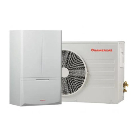
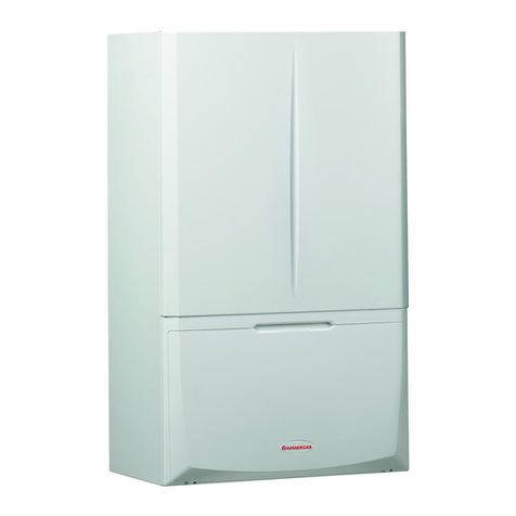
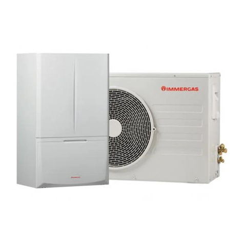
Magis Combo4-6-9V2 is a hybrid heat pumpconsistingof:
- Magis Combo4-6-9V2 indoorunit;
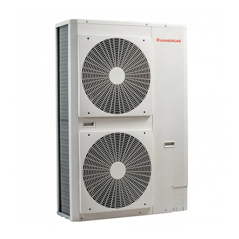
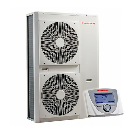
- AudaxPro 4-6-9V2outdoorcondensingunit.
Magis Combo V2 is perfectly operational only if the two units are
correctlypoweredandinterconnected.
e Magis Combo V2 indoor unit was designed solely for wall
mounted installationforheatingandair conditioningandtopro-
ducedomestic hot waterfordomesticuseandsimilarpurposes.
In order to operate properly, it must be paired with an Audax Pro
V2 condensing unit; as such, all the provisions regarding the sa-
fe t y a nd u s e of b ot h ap p l i a n c e s mu s t b e re s p e c t e d .
1.2 INSTALLATIONWARNINGS
Operatorswhoinstallandservicetheap-
pliance must wear the personal protecti-
veequipmentrequiredby applicablelaw.
e place of installation of the appliance and relative
Im me r ga s ac c e ss or i e s mus t have su it a ble feat u re s (te ch-
nical and structural), such as to allow for (always in safe,
ecientandcomfortableconditions):
- installation (according to the provisions of technical
legislationandtechnical regulations);
- maintenance operations(including scheduled,perio-
dic,routineand specialmaintenance);
- removal(tooutdoorsin theplaceforloading andtran-
sporting the appliances and components) as well as
the eventual replacement of those with appliances
and/orequivalentcomponents.
By varying the type of installation the classication of
theindoorunitalso varies, precisely:
- Type B23 o B53 indoor unit if installed using the rele-
vant terminal for air intake directly from the room in
which theboilerhas beeninstalled.
- Type Cindoorunitifinstalled using concentric pipes
orothertypesofpipesenvisionedforthesealedcham-
berboilerforintakeofair andexpulsion ofuegas.
Only a professionally enabled company is authorised to
install Immergasappliances.
e wall surface must be smooth, without any protru-
sions or recesses enabling access to the rear part. ey
are not designed to be installed on plinths or oors
(Fig. 1).
Installation must be carried out according to regulation
standards, current legislation and in compliance with
local technical regulations and the required technical
procedures.
It is forbidden to install appliances removed from other
systems.
e manufacturer declines all liability in the event of
damage caused by appliances removed from other sy-
stems orforany non-conformitieswith such equipment.
OK
1
8
INSTALLER
USERMAINTENANCETECHNICIAN
TECHNICALDATA
e appliance operates with R32 refrige-
rantgas.
isgasisODOURLESS.
Paytheutmostattention
Strictlyfollowtheinstructionhandbook
oftheUE Audax Pro outdoor unitbefore
installationandanytypeofoperationon
thechillerline.
R32 refrigerant gas belongs to the low
ammability refrigerant category: class
A2L according to standard ISO 817. It
guarantees high performance with low
environmental impact. e new gas re-
duces the potential environmental im-
pact by one third compared to R410A,
having less eect on global warning
(GWP 675).
Check the environmental operating conditions of all
partsrelevantto installation,referring to thisbooklet.
Beforeinstallingthe appliance, ensure thatit is delivered
in perfect condition; if in doubt, contact the supplier
immediately.
Packingmaterials (staples, nails, plasticbags, polystyre-
nefoam,etc.)constituteahazardandmustbe keptoutof
thereach of children.
If the appliance is installed inside or between cabinets,
ensure sucient space for routine servicing; for mini-
muminstallationdistances,seeFig. 3.
If installing a kitorservicing theappliance,always emp-
tythesystem’s domestichotwater circuitrst soas notto
compromise the appliance’selectricalsafety(Parag. 2.8,
2.9).
Always disconnect the appliance from voltage and, de-
pending on the type of operation, decrease the pressure
and/orbringitto zero inthegasandDHW circuits.
Keep allammableobjects awayfromtheappliance (pa-
per,rags, plastic, polystyrene,etc.).
Do not put household appliances under the indoor unit
as theycouldbe damagedifthesafetyvalve tripsorifthe
hydraulic ttings leak. Otherwise, the manufacturer
cannot be held liable for any damage to the household
appliances.
For the aforementioned reasons, we recommend not
placing furnishings, furniture, etc. under the indoor
unit.
Any modication to the appliance that is not explicitly
indicatedinthissectionofthebookletisforbidden.
In the event of malfunctions, faults or incorrect opera-
tion, turn the appliance o and contact an authorised
company (e.g. the Authorised Technical Assistance
Centre, which has specically trained sta and original
spare parts).
Donotattempttomodifyorrepairtheappliance alone.
9
INSTALLER
USERMAINTENANCETECHNICIAN
TECHNICALDATA
Installationstandards
is indoor unit can be installed outdoors in a partially
protected area.
Apartially protectedareais onein whichtheindoorunit
is not exposed to the direct action of the weather (rain,
snow, hail, etc.).
is type of installation is possible when permitted by
the laws in force in the appliance's country of destina-
tion.
Installation of gas appliances, ue
exhaust pipes and combustion air intake
pipes is forbidden in places with a re
risk (for example: garages, closed par-
kingstalls),andinpotentiallydangerous
places.
Do not install on the vertical projection
ofhobs.
Do not install in places/rooms that con-
stitute public areas of apartment buil-
dings, internal stairways or other escape
routes (e.g. oor landings, entrance hal-
ls,etc.).
Installation is also forbidden in places/
rooms that constitute public areas of
apartment buildings such as cellars, en-
trance halls, attics, los, etc., unless
otherwise provided for by local regula-
tionsinforce.
Inany congurationdonoinstallthein-
door unit and outdoor unit at altitudes
above2000m.
To prevent electrocution, re or injury,
always switch o the unit, disable the
protective switch and, if smoke escapes
or if the unit is extremely noisy, contact
the Authorised Aer-Sales Technical
AssistanceCentre.
10
INSTALLER
USERMAINTENANCETECHNICIAN
TECHNICALDATA
Pay attention not to generate sparks as
follows:
– Do not remove the fuses while the unit
ison.
– Donotunplugtheunitwhileitison.
It is recommended to install the outlet
high up. Lay the cables in such a way that
theydonotgettangled.
Wa l l mou nt i ng of t he i ndo or u n it mu st g u a r a nte e st able
andecientsupportforthegenerator.
e plugs (standard supply) are only to be used to x the indoor
unitto the wall; they onlyensureadequatesupport ifinserted cor-
rectly (according to technical standards) in walls made of solid or
semi-hollow brick or block. In the case of walls made from hollow
brick or block, partitions with limited static properties, or in any
case walls other than those indicated, a static test must be carried
outtoensureadequate mount.
is indoor unit is used to heat water to below boiling
temperaturein atmospheric pressure.
ey must be connected to a central heating system and
domestic hot water circuit suited to their performance
andcapacity.
e appliance is built to also operate in
coolingmode.
If cold water production, during sum-
mer,couldinterfereanddamagethecen-
tral heating onlysystems, necessary pre-
cautions must be ta ken to prevent t hat a n
unintentional production of cold water
enterstheheatingonlysystem.
Failure to comply with the above implies
personal responsibility and invalidates
thewarranty.
11
INSTALLER
USERMAINTENANCETECHNICIAN
TECHNICALDATA
1.3 MAIN DIMENSIONS
2
Key (Fig. 2):
V - Electric connection
G - Gassupply
AC - Domestichot water outlet
AF - Domestichot waterinlet
SC - Condensate drain (minimum internal
diameter Ø 13mm)
R - Systemreturn
M - Systemow
LP - Chillerline - liquid phase
GP - Chiller line-gaseous phase
Height
(mm)
Width
(mm)
Depth
(mm)
787 440 400
CONNECTIONS
LINE
CHILLERLINE GAS
DOMESTIC
HOT
WATER
SYSTEM
LP GP G AC-AF R-M
SAE 1/4” SAE 5/8” 3/4” 1/2” 3/4”
1.4 MINIMUM INSTALLATIONDISTANCES
3
Key (Fig. 3):
A - 450 mm
B - 350 mm
C - 30 mm
D - 30 mm
E - 350mm
12
INSTALLER
USERMAINTENANCETECHNICIAN
TECHNICALDATA
1.5 ANTIFREEZEPROTECTION
Minimumtemperature -5°C
e i ndo or u n it comes st a nda rd w it h a n a nt i-f re e z e f u nc t ion t h at
activates the outdoor unitwhen thetemperature ofthe waterinsi-
deofitfalls below4°C.
In these conditions, the indoor unit is protected against
freezingupto anambienttemperatureof-5℃.
Minimumtemperature-15°C
If the indoor unit is installed in a place where the tempe-
rature dropsbelow-5°C,theappliance can freeze.
Topreventthe risk offreezingfollowtheinstructionsbelow:
- protect the central heating circuit from freezing by inserting a
go od - q u a l it y a nt i f r e e z e l iq u id i nt o t h i s c i r c u it , w h i c h i s s p e c i a l-
lysuited forcentralheatingsystems andwhich ismanufacturer
guaranteed not to cause damage to the heat exchanger or other
components of the indoor unit. e antifreeze liquid must not
be harmful to one's health. e instructions of the manufactu-
rer of this liquid must be strictly followed regarding the neces-
sary percentage with respect to the minimum temperature at
whichthesystemmust be kept.
- e materials used for the central heating circuit of Immergas
indoor unit resistethylene and propylene glycolbased antifree-
ze liquids (ifthemixturesarepreparedperfectly).
- An aqueous solution must be made with potential pollution
classof water2(EN 1717:2002or localstandardsinforce).
e excessive use of glycol could jeopardise the proper
functioningoftheappliance.
For life and possible disposal, follow the
supplier'sinstructions.
- Protect the domestic hot water circuit against freezing by using
an accessory that is supplied on request (antifreeze kit) compri-
sing two electric heating elements, the relevant wiring and a
control thermostat (carefully read the installation instructions
containedintheaccessory kit pack).
In these conditions, the indoor unit is protected against
freezinguptoa temperatureof-15°C.
Indoor unit anti-freeze protection (both -5°C and -15°C) is only
ensuredif:
- indoor unit and outdoor unit are properly connected to each
otherandtotheelectrical powersupplycircuits;
- theunits arecontinuouslypowered;
- theindoorunitis notin“o” mode;
- theunits arenotin anomaly (Parag. 2.4);
- theantifreezeunit and/orkit essentialcomponentsarenotfaul-
ty.
e warranty does not cover damage due to interruption of the
electrical power supply and failure to comply with that stated on
theprevious page.
If the indoor unit is installed in places where the tempe-
rature drops below 0°C, the domestic hot water con-
nection pipes must be insulated.
eantifreeze systemsdescribedinthischapter areonly
to protect the indoor unit. e presence of these fun-
ctions and devices does not exclude the possibility of
parts of the circuits outside the indoor unit from free-
zing.
13
INSTALLER
USERMAINTENANCETECHNICIAN
TECHNICALDATA
1.6 INDOORUNITCONNECTIONUNIT
- e hyd r au l ic c onnect ion unit is standard supplie d w it h Ma g is
Combo V2. Make the hydraulic connection as shown below,
making sure to protect the system ow and return pipes with
theirsupplied insulatingsheaths.
- e R32 circuit wall connection unit is supplied as an extra kit.
Connect the circuit, following the instructions provided in the
outdoorunitinstructionsbooklet.
1.7 HYDRAULICCONNECTION
In order not to void the warranty, before making indoor
unitconnections, carefully clean theheating system(pi-
pes, radiators, etc.) with special pickling or de-scaling
products to remove any deposits that could jeopardise
proper hydronic moduleoperation.
4
LP GP
G
AC
AF
SC
RM
LP GP
GR
M
AF
AC
SC
V
5
ehydraulicconnectionkit includes(Fig. 4):
2 - Adjustableexpansion bolts
2 - indoorunit supporthooks
1 - GassupplypipeØ18(G)
1 - x1/2”cold waterinletpipe (AF)
1 - x1/2” hot waterinfeed pipe(AC)
1 - x1/2”ball valve (AF)
1 - 3/4”systemreturnpipe (R)
1 - 3/4”systemow pipe (M)
1 - 3/4”ball valve(M)
3 - Insulating sheathforsystem pipes (R - M)
1 - x1/2” telescopictting(AC)
1 - x3/4”telescopictting(R)
Gaskets, screws andsealO-Ring
e R32circuit wallconnectionkit (optional)includes:
1 - SAE1/4”liquid phase chiller linepipe (LP)
1 - SAE5/8”gaseous phasechiller line pipe(GP)
Alreadyinstalledon the module:
1 - Gascock
1 - System shut-ocock with3/4”lter(R)
Key (Fig. 5):
V - Electric connection
G - Gassupply
AC - Domestichot water outlet
AF - Domestichot waterinlet
SC - Condensate drain (minimum internaldiameter Ø 13mm)
R - Systemreturn
M - Systemow
LP - Chillerline - liquid phase
GP - Chiller line-gaseous phase
14
INSTALLER
USERMAINTENANCETECHNICIAN
TECHNICALDATA
3barsafetyvalve
edrain ofthesafetyvalvemust alwaysbeproperlyconveyedto a
draining funnel; consequently, in case of valve operation, the lea-
keduidwill end upinthesewer system.
Condensatedrain
Todrainthecondensate producedby the appliance,itis necessary
toconnect to thedrainagesystemby means ofacid condensate re-
si s t a nt pip e s , w it h a n i nte r na l Ø of a t l e a s t 13 m m .
esystem connecting theappliance to thedrainagesystemmust
be carriedoutinsuch a wayas topreventocclusionand freezingof
theliquidcontainedinit.
Before appliance ignition, ensure that the condensate can be cor-
rectly removed. Aer rst ignition, check that the drain trap is l-
ledwithcondensate.
Also, comply with national and local regulations on discharging
wastewaters.
In the event condensate is not discharged into the wastewater
drainage system, a condensate neutraliser must be installed to
ensurecompliancewiththeparameters established bythelegisla-
tioninforce.
A treatment of the heating and water system water is required, in
compliance with the technical standards in force, in order to pro-
tect the system and the appliance from deposits (e.g. scale), slurry
orotherhazardousdeposits.
In ordernotto void the heat exchangerwarranty,youarerequired
tocomplywith what hasbeenprescribed (Par. 1.28).
Water connections must be made in a rational way using the cou-
plingson the indoor unittemplate.
e manufacturer declines all liability in the event of
d a m a ge c a u s e d by t he i ns t a l la t ion o f a n aut om at i c  l l i n g
system.
In order to meet the system requirements established by EN 1717
in terms of pollution of drinking water, we recommend installing
t h e I M M E RG A S a nt i-b ac k  o w k i t t o b e u s e d u ps t r e a m of t he c ol d
water inlet connection of the indoor unit. We also recommend
using category 2 heat transfer uid (ex: water+glycol) in the boi-
ler'sprimary circuit(C.H. circuit),asdenedinstandardEN1717.
Topreserve the durationof appliance eciency features,
in the presence of water whose features can lead to the
deposit of lime scale, installation of the “polyphosphate
dispenser” kitis recommended.
If youareusing oneor more boosterpumpsitisessential
to install a hydraulic separator (not supplied by Immer-
gas)downstreamof the indoorunit.
1.8 CONNECTINGTHE CHILLERLINE
As far as connecting the cooling line is concerned, all the in-
structions contained in the outdoor unit instructions booklet
mustbefollowed.
Make the connections directly on the indoor unit couplings, or
use therearoutletkit(optional).
c
c
d
2
1
a
b
a
a
a
1
1
1
6
15
INSTALLER
USERMAINTENANCETECHNICIAN
TECHNICALDATA
1.9 ELECTRICALCONNECTION
Disconnect power to the unit before ma-
kinganyelectricalconnections.
eappliance has anIPX4D degreeofprotection;electricalsafety
of the appliance is achieved only when it is properly connected to
an ecient earthing system, as specied by current safety stan-
dards.
emanufacturerdeclines anyresponsibility fordama-
ge or physica l i nju r y c aused by fa ilu re to connect t he i n-
door unit to an ecient earthing system or failure to
complywith the IEC referencestandards.
Connectioncablesmust respect theprearranged routes.
Use 3 clips (c) (not supplied) to group the individual cables (max.
1.5 mm2intothelowerterminal board.
Use the specic fairleads (d) on the le side, making sure to put at
most 2 multi-polar cables(max 3 x 1 mm2)in each fairlead.
e gure 6 shows cables in a hypothetical connection. To make
the connections based on your own requirements, see the in-
structionsbelow.
Openthecontrol panelconnectionscompartment(Fig. 6).
To carry out electrical connections, all you have to do is open the
connectionscompartment as follows.
1. Removethefront panel.
2. Disassemble thecover.
3. Loosen thescrews(a).
4. Removethecover(b)from thecontrol panel(c).
Atthis point,youcan access theterminalboard.
Also ensure that the electrical installation corresponds to maxi-
mum absorbed power specications as shown on the indoor unit
data-plate.
Indoor units are supplied complete with a “Y” type power cable
withoutplug.
e power supply cable must be con-
nectedtoa230V±10%/50Hzmainssup-
ply respecting L-N polarity and earth
connection; this network must also have
amulti-polecircuitbreakerwithclassIII
overvoltage category in compliance with
installationregulations.
To protect from possible dispersions of
DC voltage, it is necessary to provide a
typeAdierentialsafetydevice.
If the power cable is damaged, contact a
qualied company (e.g. the Authorised
Technical Assistance Centre) for its re-
placementtoavoidahazard.
e power cable must follow the prescribed route (Par. 1.7); avoi-
dingcontactwiththesideoftheframe.
If the fuses on the circuitboardsneedtobe replaced,thismustalso
be done by qualied personnel: use a F3.15A H250V fuse on the
P.C.B.
For the main power supply to the appliance, never use adapters,
multiplesocketsorextensionleads.
Make the various electrical connections according to your needs
(Fig. 7, 8):
Outdoorunitelectricalconnection
eindoorunit mustbe coupledtoan AudaxPro V2outdoorunit
by connecting terminals F1 and F2 as shown in the wiring dia-
gram(Fig. 8). eAudaxProV2outdoorunitispoweredat230V,
independently fromtheindoorunit.
Congure the indoor unit parameters as indicated in paragraph
(Parag. 3.12).
Photovoltaic systeminstallation
Connecting the product to a photovoltaic system enhances use of
theoutdoorunitwhen the photovoltaic panelsareoperating. Car-
ryouttheconnectionasindicated(Fig. 7).
Dehumidiers
Carry out the connection as indicated (Fig. 8). To complete the
connection operations,insertthe 2-relayBoardoptional kit.
It is compulsory to set up separate lines
with dierent power supply voltages,
particularly it is essential to separate the
very low voltage connections from the
230Vones.
No product pipes must ever be used to
earth the electric system or telephone li-
nes.
Ensure elimination of this risk before
making the indoor unit electrical con-
nections.
e indoor unit can be electrically con-
nectedtooutdoorunitswithverylowvol-
ta ge safet y ci rcuits (SE LV)
16
INSTALLER
USERMAINTENANCETECHNICIAN
TECHNICALDATA
Lowvoltageelectricalconnectiondiagram.
1
23
1
1
4
5
6
7
Termina l 87
0V Close Winter
230V Open Summerwithcooling
Key (Fig. 7):
1 - Open/Close
2 - Close
3 - Open
4 - Valvewith springreturn
5 - valve with2points
6 - Auxiliaries
M10-1 - Zone1pump (optional)
M10-2 - Zone2 circulator pump (optional)
M10-3 - Zone3circulatorpump (optional)
M31-2 - Zone 2 mixingvalve(optional)
M52 - Hotcoldthree-way(optional)
S39 - Solarinlet
S41 - Outdoorunitdeactivation
A 3rd zone (mixed) can also be managed on the system by means
ofthecongurablerelayinterface kit(optional).
In this case, the zone 3 pump must be connected according to dia-
gram (M10-3).
e zone 3 dehumidier, if any, will be managed by means of the
congurable relay interface kit, which the zone 3 mixer will also
beconnectedto.
17
INSTALLER
USERMAINTENANCETECHNICIAN
TECHNICALDATA
Electricalconnectiondiagram (verylowvoltage).
1
8
A16-1 and A16-2 dehumidiers can be connected only aer in-
stalling 2-relayboard(optional).
Remove jumper X40-1 before the electrical connection of the
ro om t he r mo s t a t z one 1.
Key (Fig. 8):
A13 - Systemmanager (optional)
A16-1 - Zone 1 dehumidier (optional with dehumidier
managementboard)
A16-2 - Zone 2 dehumidier (optional - with dehumidier
managementboard)
A17-1 - Zone 1 humidity sensor(optional)
A17-2 - Zone 2 humidity sensor(optional)
A17-3 - Zone 3 humidity sensor(optional)
A23 - Externalunit
A30 - Dominus
A32-1 - Zone1remotepanel(optional)
A32-2 - Zone2remotepanel(optional)
A32-3 - Zone 3 remote panel (optional)
B3-2 - Zone 2 ow probe(optional)
B3-3 - Zone 3 ow probe(optional)
B4 - Externalprobe (optional)
B9 - DHWinletprobe (optional)
B13 - Central heating probe(optional)
E7-2 - Zone 2 low temperature safety thermostat (optio-
nal)
E7-3 - Zone 3 low temperature safety thermostat (optio-
nal)
S20-1 - Zone1room thermostat(optional)
S20-2 - Zone2room thermostat(optional)
S20-3 - Zone3room thermostat(optional)
S36-1 - Zone 1 humidistat (optional)
S36-2 - Zone 2 humidistat (optional)
S36-3 - Zone3humidistat (optional)
S44 - Heating /Coolingselector
X40-1 - Zone 1 roomthermostatjumper
1 - Service connector
18
INSTALLER
USERMAINTENANCETECHNICIAN
TECHNICALDATA
1.10 ROOM CHRONOTHERMOSTATS
OPTIONAL
e indoor unit is prepared for the application of room chro-
no-thermostats or remote controls, which are available as optio-
nalkits (Fig. 9).
A maximum of 3 temperature controllers can be applied directly
totheappliance.
All Immergas chrono-thermostats are connected with 2 wires
only.
Carefully read the user and assembly instructions contained in
theaccessorykit.
Carry outtheconnectionasindicated(Fig. 8).
Disconnect power to the unit before ma-
kinganyelectricalconnections.
On/O Immergasdigitalchrono-thermostat.
echrono-thermostat allows:
- set two room temperature value: one for day (comfort tempera-
ture)andonefornight(reduced temperature);
- set a weekly programmewithfourdaily switch onandswitcho
times;
- selecting the required function mode from the various possible
alternatives:
• manual mode (with adjustabletemperature);
• automaticmode (withset programme);
• forced automatic operation (momentarily changing the tem-
perature of theautomaticprogram).
echrono-thermostat is powered by two1.5VLR6typealkaline
batteries.
On/O chrono-thermostatelectricalconnection(Optional).
e operations described below must be
performed aer having removed thevol-
tagefromtheappliance.
On/O ambient thermostat or chrono-thermostat: must be con-
nected to the 40-1 / 41 terminals, eliminating the X40-1 jumper
forzone1 and40-2/41forzone2 and40-3 / 42forzone3.
Make sure that the On/O thermostat contact is of the “clean”
type, i.e. independent of the mains voltage, otherwise the P.C.B.
would be damaged.
e connections must be made on the terminal board inside the
appliance’scontrol panel (Fig. 8).
1.11 MODBUS TEMPERATURE AND
HUMIDITYROOMPROBESOPTIONAL
e temperature and humidity probe is used to detect room hu-
midity and to calculate the relative dew point by regulating the
owtemperatureduringthecoolingphase.
Connect the appliance asshown (Fig. 8).
DIP-Switchcongurationtable
ON
123 4567 8
DIP 1-5 DIP 6-7 DIP 8
DIP1-5
(Address)
ON
123 45
Zone1
(Address
131)
ON
123 45
Zone2
(Address
132)
ON
123 45
Zone3
(Address
133)
DIP6-7
(Type)
ON
67
Modbus 1 - 8
-E-1
DIP8
(Speed)
ON
8
9600 bit/s
19
INSTALLER
USERMAINTENANCETECHNICIAN
TECHNICALDATA
1.12 REMOTE ZONE CONTROL OPTIONAL
is remote device is used to adjust the setpoints and to view the
maininformationofthezonewhere it wascongured.
Connectasshown (Fig. 8);
To correctly congure the device, set the parameters as described
below:
AssistanceMenu->Deviceconguration
Sl a ve a d d r e s s : Ad d r e s s t o c on  g u r e a c c o r d i n g t o
thezone where the device is installed
Zone 1 = 41
Zone 2 = 42
Zone 3 = 43
BaudRate 9600
Paritybit Even
Stopbits 1
Heat pump control NO
Forcorrectoperationitis necessary toinstall thejumper
onthethermostatofthezoneassociatedtothepanel.
If necessary, this jumper can be replaced with a safety
thermostat.
128
99
37
9
1.13 DOMINUS OPTIONAL
e system can be remote controlled using the optional Dominus
kit.
Connect the appliance asshown (Fig. 8).
Forfurtherinformation,consulttherelativeinstruction sheet.
1.14 HUMIDISTAT ON/OFF OPTIONAL
Youcan makea dehumidicationdemandbyusing a humidistat.
Connectasshown (Fig. 8)
1.15 EXTERNALTEMPERATUREPROBE
OPTIONAL
In theoutdoorunitthereis anexternal probeasstandard.
iscan be usedasanexternalprobeof the heatpump.
If the outdoor unit is positioned in an area that is not suitable for
temperature reading, it is advisable to use an additional external
probe(Fig. 10) which is availableasanoptional kit.
Refer to the relative instruction sheet for positioning of the exter-
nalprobe.
For the proper operation of the optional probe it must be con-
nected where envisaged (Fig. 8) and then it must be enabled (Pa-
rag. 3.12).
Once the probe is enabled, switch the ap-
plianceoandbackon.
e presence of the external probe allows the system ow tempe-
ratureto beset automaticallybasedontheoutdoortemperaturein
ordertoadapttheheating orcoolingprovidedto the system.
e system ow temperature is determined by the setting on the
“Heat regulation” menu and by the “User” menu for the oset va-
luesbasedonthecurves shown inthediagram (Parag. 1.16).
If the system is divided into two or three zones, the ow
temperature is calculated based on the zone with the hi-
gher temperature in central heating mode and with the
lower temperatureincoolingmode.
e electric connection of the external probe must be made on
terminals38and39onthe terminalboard on theindoorunitcon-
trol panel(Fig. 8).
45
31
58
10
I n c a s e of f a i lu r e , a  e r h av i n g p owe re d o  a n d ba c k o n, t he out do -
or temperature is automatically detected by the external probe on
theoutdoorunit.
20
INSTALLER
USERMAINTENANCETECHNICIAN
TECHNICALDATA
1.16 TEMPERATURE CONTROLSETTING
By setting the parameters in the “Heat regulation” menu, you can
adjusthowthesystemoperates.
e curves (Fig. 11, 13, 12, 14, 15, 16) show the default settings in
the various operating modes available both with external probe
andwithout.
Zone 1owtemperatureincentralheating mode
e , w i t h e x t e r n a l p ro b e
R04
R05
R02 R03
U03
11
Zone 1owtemperatureincoolingmode
,withexternal probe
R13
R12
R11 R10
U05
12
Zone 2 (3)mixed
owtemperatureincentralheating mode,withexternal probe
R08
(R23)
R09
(R24)
R06 (R21) R07 (R22)
(U16)
U04
13
Zone 2 (3)mixed
owtemperatureincooling mode,withexternal probe
(R28)
R17
R16
(R27)
R15 (R26) R14 (R25)
(U17)
U06
14
Key (Fig. 11,12,13,14)
Rxx - “Temperature control”menuparameter
TE - External temperature
TM - Flow temperature
U03 - Oset value compared to the curve set by the external probe
oncentralheatingzone 1.
U04 - Oset value compared to the curve set by the external probe
oncentralheatingzone 2.
U05 - Oset value compared to the curve set by the external probe
oncoolingzone1
U06 - Oset value compared to the curve set by the external probe
oncoolingzone2
U16 - Oset value compared to the curve set by the external probe
oncentralheatingzone 3
U17 - Oset value compared to the curve set by the external probe
oncoolingzone3

This manual suits for next models

2

Other Immergas Heat Pump manuals

Immergas VICTRIX HYBRID User manual

Immergas

Immergas VICTRIX HYBRID User manual

Immergas 3.023355 User manual

Immergas

Immergas 3.023355 User manual

Immergas TRIO PACK ELECTRIC 4 Product manual

Immergas

Immergas TRIO PACK ELECTRIC 4 Product manual

Immergas MAGIS HERCULES PRO User manual

Immergas

Immergas MAGIS HERCULES PRO User manual

Immergas UE AUDAX PRO 12 V2 Operating instructions

Immergas

Immergas UE AUDAX PRO 12 V2 Operating instructions

Immergas Magis M 4 EH3 Technical manual

Immergas

Immergas Magis M 4 EH3 Technical manual

Immergas MAGIS COMBO PLUS Series Product manual

Immergas

Immergas MAGIS COMBO PLUS Series Product manual

Immergas MAGIS M4-6-8 EH3 Operating instructions

Immergas

Immergas MAGIS M4-6-8 EH3 Operating instructions

Immergas MAGIS M 4 Product manual

Immergas

Immergas MAGIS M 4 Product manual

Immergas IMMERWATER 190S V5 Product manual

Immergas

Immergas IMMERWATER 190S V5 Product manual

Immergas AUDAX PRO 5 Product manual

Immergas

Immergas AUDAX PRO 5 Product manual

Immergas TRIO PACK HYBRID 4 Product manual

Immergas

Immergas TRIO PACK HYBRID 4 Product manual

Immergas 3.023355 User manual

Immergas

Immergas 3.023355 User manual

Immergas AUDAX PRO 4 V2 Product manual

Immergas

Immergas AUDAX PRO 4 V2 Product manual

Immergas MAGIS HERCULES PRO 4 Operating instructions

Immergas

Immergas MAGIS HERCULES PRO 4 Operating instructions

Immergas Rapax 300 V2 Operating instructions

Immergas

Immergas Rapax 300 V2 Operating instructions

Immergas Magis Combo 5 Product manual

Immergas

Immergas Magis Combo 5 Product manual

Immergas AUDAX PRO 4 V2 Product manual

Immergas

Immergas AUDAX PRO 4 V2 Product manual

Immergas AUDAX TOP 6 ErP Operating instructions

Immergas

Immergas AUDAX TOP 6 ErP Operating instructions

Immergas SUPER TRIO User manual

Immergas

Immergas SUPER TRIO User manual

Immergas MAGIS COMBO PLUS V2 Series Operating instructions

Immergas

Immergas MAGIS COMBO PLUS V2 Series Operating instructions

Immergas AUDAX TOP Operating instructions

Immergas

Immergas AUDAX TOP Operating instructions

Immergas MAGIS PRO 4 V2 Operating instructions

Immergas

Immergas MAGIS PRO 4 V2 Operating instructions

Immergas MAGIS COMBO PLUS 5 Product manual

Immergas

Immergas MAGIS COMBO PLUS 5 Product manual

Popular Heat Pump manuals by other brands

Airwell CKD Series Service manual

Airwell

Airwell CKD Series Service manual

LG MULTI-V SE Series owner's manual

LG

LG MULTI-V SE Series owner's manual

J&E Hall JEHSD-0600-M-3 Technical manual

J&E Hall

J&E Hall JEHSD-0600-M-3 Technical manual

Nibe AG-WT10 series Installer manual

Nibe

Nibe AG-WT10 series Installer manual

STIEBEL ELTRON HPA-O 4 CS Plus Operation and installation instruction

STIEBEL ELTRON

STIEBEL ELTRON HPA-O 4 CS Plus Operation and installation instruction

Johnson Controls UC installation manual

Johnson Controls

Johnson Controls UC installation manual

Trane FLEX HP HT Installation operation & maintenance

Trane

Trane FLEX HP HT Installation operation & maintenance

System air SYSCROLL 20 AIR EVO HP Installation and maintenance manual

System air

System air SYSCROLL 20 AIR EVO HP Installation and maintenance manual

Aqua PRO VIGOH55 owner's manual

Aqua PRO

Aqua PRO VIGOH55 owner's manual

Fondital WHPF 200 PU Installation, use and maintenance handbook

Fondital

Fondital WHPF 200 PU Installation, use and maintenance handbook

Amana RHA**B*A installation instructions

Amana

Amana RHA**B*A installation instructions

Daikin ELVZ-E9W installation manual

Daikin

Daikin ELVZ-E9W installation manual

Heat Controller RPHE-093G Series Installation & operation manual

Heat Controller

Heat Controller RPHE-093G Series Installation & operation manual

Mitsubishi Electric QUHZ-W40VA Service manual

Mitsubishi Electric

Mitsubishi Electric QUHZ-W40VA Service manual

HTW VAX Owners and installation manual

HTW

HTW VAX Owners and installation manual

Daikin altherma ERHQ011BAV3 installation manual

Daikin

Daikin altherma ERHQ011BAV3 installation manual

Viessmann VITOCAL 300 Installation and service instructions

Viessmann

Viessmann VITOCAL 300 Installation and service instructions

Rotex RKHB 016BA3V3 Series Operation manual

Rotex

Rotex RKHB 016BA3V3 Series Operation manual

manuals.online logo
manuals.online logoBrands
  • About & Mission
  • Contact us
  • Privacy Policy
  • Terms and Conditions

Copyright 2025 Manuals.Online. All Rights Reserved.