manuals.online logo
Brands
  1. Home
  2. •
  3. Brands
  4. •
  5. Immergas
  6. •
  7. Heat Pump
  8. •
  9. Immergas MAGIC COMBO PLUS Series Product manual

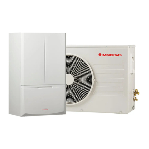
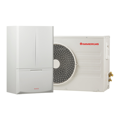
Immergas MAGIC COMBO PLUS Series Product manual

This manual suits for next models

3

Other Immergas Heat Pump manuals

Immergas MAGIS M4-6-8 EH3 Operating instructions

Immergas

Immergas MAGIS M4-6-8 EH3 Operating instructions

Immergas AUDAX PRO 5 Product manual

Immergas

Immergas AUDAX PRO 5 Product manual

Immergas UE AUDAX PRO 12 V2 Operating instructions

Immergas

Immergas UE AUDAX PRO 12 V2 Operating instructions

Immergas AUDAX TOP Operating instructions

Immergas

Immergas AUDAX TOP Operating instructions

Immergas Magis Combo 5 Product manual

Immergas

Immergas Magis Combo 5 Product manual

Immergas HYDRO 3 Product manual

Immergas

Immergas HYDRO 3 Product manual

Immergas 3.023355 User manual

Immergas

Immergas 3.023355 User manual

Immergas Trio Base V2 User manual

Immergas

Immergas Trio Base V2 User manual

Immergas MAGIS M 4 Product manual

Immergas

Immergas MAGIS M 4 Product manual

Immergas Rapax 300 V2 Operating instructions

Immergas

Immergas Rapax 300 V2 Operating instructions

Immergas Magis M 4 EH3 Technical manual

Immergas

Immergas Magis M 4 EH3 Technical manual

Immergas AUDAX PRO 4 V2 Product manual

Immergas

Immergas AUDAX PRO 4 V2 Product manual

Immergas AUDAX PRO 5 Operating instructions

Immergas

Immergas AUDAX PRO 5 Operating instructions

Immergas 3.028187 Product manual

Immergas

Immergas 3.028187 Product manual

Immergas TRIO PACK ELECTRIC 4 Product manual

Immergas

Immergas TRIO PACK ELECTRIC 4 Product manual

Immergas MAGIS HERCULES PRO MINI 6 Operating instructions

Immergas

Immergas MAGIS HERCULES PRO MINI 6 Operating instructions

Immergas Magis Combo Series Product manual

Immergas

Immergas Magis Combo Series Product manual

Immergas AUDAX TOP ErP Series User manual

Immergas

Immergas AUDAX TOP ErP Series User manual

Immergas MAGIS COMBO PLUS Series Product manual

Immergas

Immergas MAGIS COMBO PLUS Series Product manual

Immergas MAGIS COMBO Product manual

Immergas

Immergas MAGIS COMBO Product manual

Immergas MAGIS COMBO Product manual

Immergas

Immergas MAGIS COMBO Product manual

Immergas MAGIS COMBO PLUS 5 Product manual

Immergas

Immergas MAGIS COMBO PLUS 5 Product manual

Immergas AUDAX TOP 21 ErP Operating instructions

Immergas

Immergas AUDAX TOP 21 ErP Operating instructions

Immergas AUDAX TOP 6 ErP Operating instructions

Immergas

Immergas AUDAX TOP 6 ErP Operating instructions

Popular Heat Pump manuals by other brands

Daikin RXL12QMVJU Service manual

Daikin

Daikin RXL12QMVJU Service manual

AIREDALE BluCube CUR092V16-1CO-0 Installation and maintenance manual

AIREDALE

AIREDALE BluCube CUR092V16-1CO-0 Installation and maintenance manual

Calyenty RBH 125 Customer's manual

Calyenty

Calyenty RBH 125 Customer's manual

GRE HPGI50 owner's manual

GRE

GRE HPGI50 owner's manual

Carrier 30XW Installation, operation and maintenance instructions

Carrier

Carrier 30XW Installation, operation and maintenance instructions

Hayward SUMHEAT HP5131DT3 Installation instructions manual

Hayward

Hayward SUMHEAT HP5131DT3 Installation instructions manual

REMKO SQW 400 Electrical wiring

REMKO

REMKO SQW 400 Electrical wiring

Sanyo SAP120FCH Service manual

Sanyo

Sanyo SAP120FCH Service manual

Daikin EHYHBH05AA Operation manual

Daikin

Daikin EHYHBH05AA Operation manual

Panasonic WH-SDF03E3E5 Design handbook

Panasonic

Panasonic WH-SDF03E3E5 Design handbook

Airxcel 45000 Series Installation, operation and maintenance instructions

Airxcel

Airxcel 45000 Series Installation, operation and maintenance instructions

Mitsubishi Electric PUZ-SWM60VAA Service manual

Mitsubishi Electric

Mitsubishi Electric PUZ-SWM60VAA Service manual

Dimplex LI 16I-TUR Installation and operating instruction

Dimplex

Dimplex LI 16I-TUR Installation and operating instruction

Carrier WSHP Open v3 Integration guide

Carrier

Carrier WSHP Open v3 Integration guide

Mitsubishi Electric EHSE-YM9EC Service manual

Mitsubishi Electric

Mitsubishi Electric EHSE-YM9EC Service manual

TGM CTV14CN018A Technical manual

TGM

TGM CTV14CN018A Technical manual

Carrier 38MGQ Series installation instructions

Carrier

Carrier 38MGQ Series installation instructions

Kokido K2O K880BX/EU Owner's manual & installation guide

Kokido

Kokido K2O K880BX/EU Owner's manual & installation guide

manuals.online logo
manuals.online logoBrands
  • About & Mission
  • Contact us
  • Privacy Policy
  • Terms and Conditions

Copyright 2025 Manuals.Online. All Rights Reserved.

MAGIS COMBO
PLUS
5 - 8 - 10
Hybrid heat pumps
IE
Instructions and warnings
Installer
User
Maintenance technician
*1.040375ENG*
e manufacturer declines all liability due to printing or transcription errors, reserving the right to make any modications to its technical and commercial
documents without prior notice.
Dear Customer,
Our compliments for having chosen a top-quality Immergas product, able to assure well-being and safety for a long period of time. As an Immergas Customer,
you can also count on a qualied aer-sales service, prepared and updated to guarantee constant eciency of your product. Read the following pages carefully:
you will be able to draw useful suggestions regarding the correct use of the appliance. By respecting these suggestions, you will no doubt be satised with your
Immergas product.
For any assistance and scheduled maintenance please contact Authorised Aer-Sales centres: they have original spare parts and are specically trained by the
manufacturer.
General recommendations
All Immergas products are protected with suitable transport packaging.
e material must be stored in a dry place protected from the weather.
e instruction book is an integral and essential part of the product and must also be given to the new user in the case of transfer or succession of ownership.
It must be stored with care and consulted carefully, as all of the warnings provide important safety indications for installation, use and maintenance stages.
is instructions manual provides technical information for installing Immergas products. As for the other issues related to product installation (e.g. safety
in the work site, environment protection, injury prevention), it is necessary to comply with the provisions specied in the regulations in force and principles
of good practice.
In compliance with legislation in force, the systems must be designed by qualied professionals, within the dimensional limits established by the Law. Installation
and maintenance must be performed in compliance with the regulations in force, according to the manufacturer's instructions and by an authorised company,
which has specic technical expertise in the system sector, as required by Law.
Improper installation or assembly of the appliance and/or Immergas components, accessories, kit and devices can cause unexpected problems to people, animals
and objects. Read the instructions provided with the product carefully to ensure proper installation.
Maintenance must be carried out by an authorised company. e Authorised Aer-sales Service represents a guarantee of qualication and professionalism.
e appliance must only be destined for the use for which it has been expressly declared. Any other use will be considered improper and therefore potentially
dangerous.
If errors occur during installation, operation and maintenance, due to non-compliance with technical laws in force, standards or instructions contained in
this book (or however supplied by the manufacturer), the manufacturer is excluded from any contractual and extra-contractual liability for any damages and
the appliance warranty is invalidated.
e company IMMERGAS S.p.A., with registered oce in via Cisa Ligure 95 42041 Brescello (RE), declares that the design, manufacturing and aer-sales
assistance processes comply with the requirements of standard UNI EN ISO 9001:2015.
For further details on the product CE marking, request a copy of the Declaration of Conformity from the manufacturer, specifying the appliance model
and the language of the country.
INDEX
USER......................................................... pageINSTALLER............................................. page MAINTENANCE TECHNICIAN........ page
1 Installing the indoor unit...........................4
1.1 Installation recommendations. .................4
1.2 Main dimensions ........................................5
1.3 Antifreeze protection. ................................5
1.4 Connection group....................................... 6
1.5 Hydraulic connection.................................6
1.6 Connecting the chiller line........................7
1.7 Electrical connection. ................................7
1.8 Remote controls and room chrono-
thermostats (optional). ..............................9
1.9 External temperature probe. .....................9
1.10Heat regulation setting.............................10
1.11Immergas ue systems.............................11
1.12Tables of resistance factors and equivalent
lengths........................................................11
1.13Outdoor installation in partially protected
area..............................................................13
1.14Concentric horizontal kit installation....14
1.15Concentric vertical kit installation.........15
1.16Separator kit installation..........................16
1.17Adaptor c9 kit installation. .....................17
1.18Ducting of ues or technical slots. .........18
1.19Conguration type b, open chamber and
fan assisted for indoors. ...........................18
1.20Flue exhaust to ue/chimney. .................18
1.21Flues, chimneys, chimney pots and
terminals....................................................19
1.22Filling the system......................................19
1.23Filling the condensate drain trap............19
1.24Gas system commissioning. ....................19
1.25Operating limits in heat pump mode.....19
1.26Heat generator commissioning (ignition,
only coupled with a condensing unit)....20
1.27Circulation pump......................................21
1.28Indoor unit components..........................22
1.29Kits available on request. .........................22
2 Use and maintenance instructions.........23
2.1 Cleaning and maintenance......................23
2.2 General warnings......................................23
2.3 Control panel.............................................23
2.4 System use..................................................24
2.5 Fault and anomaly signals. ......................26
2.6 Parameters and information menu. .......29
2.7 Indoor unit shutdown. .............................30
2.8 Restore central heating system pressure 30
2.9 Draining the system. ................................30
2.10Antifreeze protection. ..............................30
2.11Case cleaning.............................................30
2.12Decommissioning.....................................30
3 Magis combo plus 5 - 8 - 10 start-up
(initial check) ............................................31
3.1 Hydraulic diagram....................................31
3.2 Wiring diagram.........................................32
3.3 System lter. ..............................................35
3.4 Troubleshooting........................................35
3.5 Gas valve. ...................................................36
3.6 Converting the heat generator to other
types of gas.................................................36
3.7 Calibration of number of fan revs. .........36
3.8 Adjustment of the air-gas ratio. ..............36
3.9 Checks following conversion to another
type of gas..................................................36
3.10Programming the p.C.B...........................37
3.11“Chimney sweep” function......................41
3.12Pump anti-lock function. ........................41
3.133-Way anti-lock function.........................41
3.14Radiators antifreeze function..................41
3.15Solar function............................................41
3.16Outdoor unit disable function................41
3.17Preheating function..................................41
3.18Diverter valve management
(summer / winter). ...................................41
3.19Automatic vent function..........................42
3.20Screed heater function. ............................42
3.21Dehumidication function......................42
3.22Audax pro testmode function.................42
3.23Generators management..........................42
3.24Yearly appliance check and maintenance. ..
...............................................................43
3.25Casing removal. ........................................44
3.26Condensate trap siphon disassembly. ....45
3.27Technical data. ..........................................46
3.28Combustion parameters. .........................47
3.29Product che (in compliance with
regulation 811/2013)................................48
3.30Parameters for lling the package che. 54
4
1
INSTALLERUSERMAINTENANCE TECHNICIAN
1INSTALLING THE INDOOR
UNIT
1.1 INSTALLATION
RECOMMENDATIONS.
e Magis Combo Plus indoor unit was designed
solely for wall mounted installation for heating
and air conditioning and to produce domestic
hot water for domestic use and similar purposes.
In order to operate properly, it must be paired
with an Audax Pro condensing unit; as such,
all the provisions regarding the safety and use
of both the indoor and outdoor units must be
respected.
e place of installation of the two units and
relative Immergas accessories must have suitable
features (technical and structural), such as to al-
low for (always in safe, ecient and comfortable
conditions):
- installation (according to the provisions of
technical legislation and technical regulations);
- maintenance operations (including scheduled,
periodic, routine, special);
- removal (to outdoors in the place for loading
and transporting the appliances and com-
ponents) as well as the eventual replacement
of those with appliances and/or equivalent
components.
e wall surface must be smooth, without any
protrusions or recesses enabling access to the
rear part. ey are not designed to be installed
on plinths or oors (Fig. 1).
By varying the type of installation the classi-
cation of the indoor unit also varies, precisely:
- Type B23 B53 if installed using the relevant
terminal for air intake directly from the room
in which the indoor unit has been installed.
- Type C if installed using concentric pipes or
other types of pipes envisioned for the sealed
chamber indoor units for intake of air and
expulsion of ue gas.
Only professionally enabled companies are
authorised to install Immergas gas appliances.
Installation must be carried out according to
regulation standards, current legislation and in
compliance with local technical regulations and
the required technical procedures.
Attention: the manufacturer declines all liability
in the event of damage caused by appliances
removed from other systems or for any non-con-
formities with such equipment.
Before installing the indoor unit, ensure that it is
delivered in perfect condition; if in doubt, contact
the supplier immediately. Packing materials (sta-
ples, nails, plastic bags, polystyrene foam, etc.)
constitute a hazard and must be kept out of the
reach of children.
If the appliance is installed inside or between
cabinets, ensure sucient space for normal ser-
vicing; therefore it is advisable to leave clearance
of at least 30 cm on the right and a clearance on
the le of at least 3 cm between the casing of the
indoor unit and the vertical sides of the cabinet.
Leave adequate space above the indoor unit for
possible water and ue removal connections.
Keep all ammable objects away from the ap-
pliance (paper, rags, plastic, polystyrene, etc.).
Do not put household appliances under the
indoor unit as they could be damaged if the
safety valve trips or if the hydraulic ttings leak.
Otherwise, the manufacturer cannot be held lia-
ble for any damage to the household appliances.
For the aforementioned reasons, we recommend
not placing furnishings, furniture, etc. under the
indoor unit.
In the event of malfunctions, faults or incorrect
operation, turn the appliance o immediately
and contact an authorised company (e.g. the
Authorised Technical Assistance centre, which
has specically trained sta and original spare
parts). Do not attempt to modify or repair the
appliance alone.
Failure to comply with the above implies personal
responsibility and invalidates the warranty.
• Installation Standards:
- this indoor unit can be installed outdoors in a
partially protected area. A partially protected
area is one in which the indoor unit is not
exposed to the direct action of the weather
(rain, snow, hail, etc..).
NOTE: this type of installation is only possible
when permitted by the laws in force in the
appliance's country of destination.
- Installation of gas appliances, ue exhaust
pipes and combustion air intake pipes is
forbidden in places with a re risk (for ex-
ample: garages, closed parking stalls), and
in potentially dangerous places.
- Installation is prohibited on the vertical
projection of the cooking surface.
- Installation is forbidden in places/rooms
that constitute public areas of apartment
buildings, internal stairways or other escape
routes (e.g. oor landings, entrance halls,
etc.).
- Installation is also forbidden in places/rooms
that constitute public areas of apartment
buildings such as cellars, entrance halls, attics,
los, etc., unless otherwise provided for by
local regulations in force.
Attention: wall mounting of the indoor unit
must guarantee stable and ecient support for
the generator.
e dowels (standard supplied with the unit) must
only be used to secure the unit to the wall; they can
only ensure sucient support if inserted properly
(according to the rules of good practice) on walls
built with solid or semi-hollow bricks. In the
case of walls made from hollow brick or block,
partitions with limited static properties, or in any
case walls other than those indicated, a static test
must be carried out to ensure adequate mount.
This product is used to heat water to below
boiling temperature in atmospheric pressure.
It must be connected to a central heating system
and domestic hot water circuit suited to its per-
formance and capacity.
Attention:e storage tank unit must also be
installed in an environment in which the tem-
perature cannot fall below 0°C.
"Anti-legionella" heat treatment of the Immergas
storage tank (activated by the specic function
present on the predisposed thermoregulatory
systems): during this stage, the temperature of
the water inside the storage tank exceeds 60°C
with a relative risk of burns. Keep this domestic
water treatment under control (and inform
the users) to prevent unforeseeable damage
to people, animals, things. If required install a
thermostatic valve on the domestic hot water
outlet to prevent scalding.
YES NO
5
2
INSTALLERUSERMAINTENANCE TECHNICIAN
1.2 MAIN DIMENSIONS
Key:
V - Electrical connection
G - Gas supply
LP - Chiller line - liquid phase
GP - Chiller line - gaseous phase
RU - Storage tank unit return
MU - Storage tank unit ow
RR - System lling
SC - Condensate drain (minimum
internal diameter Ø 13 mm)
R - System return
M - System ow
Height
(mm)
Width
(mm)
Depth
(mm)
787 440 400
CONNECTIONS
CHILLER
LINE GAS DOMESTIC
HOT WATER SYSTEM
LP GP G RR R - M MU - RU
G 3/8” G 5/8” 3/4” 1/2” 3/4” 3/4"
1.3 ANTIFREEZE PROTECTION.
Minimum temperature -5°C. e indoor unit
comes standard with an anti-freeze function
that activates the condensing unit and the heat
generator when the temperature of the water
inside of it falls below 4°C.
In these conditions, the indoor unit is protected
against freezing up to an ambient temperature
of -5°C.
Minimum temperature -15°C.If the indoor
unit is installed in a place where the temperature
drops below -5°C, the appliance can freeze.
To prevent the risk of freezing follow the instruc-
tions below:
- protect the central heating circuit from freezing
by inserting a good-quality antifreeze liquid
into this circuit, which is specially suited for
central heating systems and which is manu-
facturer guaranteed not to cause damage to
the heat exchanger or other components of
the hydronic module. e antifreeze liquid
must not be harmful to one's health. e in-
structions of the manufacturer of this liquid
must be followed scrupulously regarding the
percentage necessary with respect to the min-
imum temperature at which the system must
be kept. An aqueous solution must be made
with potential pollution class of water 2 (EN
1717:2002 or local standards in force).
Warning: the excessive use of glycol could jeop-
ardise the proper functioning of the appliance.
e materials used for the hydraulic circuits of
Immergas hydronic units resist ethylene and
propylene glycol based antifreeze liquids (if the
mixtures are prepared perfectly).
For life and possible disposal, follow the sup-
plier's instructions.
- Protect the domestic hot water circuit against
freezing by using an accessory that is supplied
on request (antifreeze kit) comprising two
electric heating elements, the relevant wiring
and a control thermostat (carefully read the
installation instructions contained in the ac-
cessory kit pack).
In these conditions, the indoor unit is protected
against freezing up to a temperature of -15°C.
Indoor unit anti-freeze protection (both -5°C and
-15°C) is only ensured if:
- e indoor unit and the condensing unit are
properly connected to each other and to the
electrical supply voltage circuits;
- e units are continuously powered;
- the units are not in "o" mode.
- the units are not in anomaly (Para. 2.5);
- the unit and/or kit essential components are not
faulty.
e warranty does not cover damage due to inter-
ruption of the electrical power supply and failure
to comply with that stated on the previous page.
N.B.: if the unit is installed indoors, where the
temperature drops below 0°C, both the DHW
and central heating connection pipes must be
insulated.
e water in the storage tank unit is not protected
against freezing when the boiler is switched o.
6
LP GP
G
RU
RR
SC
RM
LP GP
GR
M
MU
RU
SC
V
RR
MU
1
2
3
4
3
INSTALLERUSERMAINTENANCE TECHNICIAN
e hydraulic connection kit includes:
N° 2 - adjustable expansion bolts
N° 2 - indoor unit support hooks
N° 1 - Gas supply pipe Ø 18 (G)
No. 1 - 1/2” system lling inlet pipe (RR)
N° 1 - 3/4” storage tank unit ow pipe (MU)
N° 1 - 3/4” storage tank unit return pipe (RU)
N° 1 - 1/2” ball valve (RR)
N° 1 - 3/4” system return pipe (R)
N° 1 - 3/4” system ow pipe (M)
N° 1 - 3/4” ball valve (M)
N° 3 - Insulating sheath for system pipes (R - M)
N° 1 - Telescopic tting 3/4” (MU)
N° 1 - 3/4” telescopic tting (RU)
Gaskets, screws and seal O-Ring
e R410A circuit wall connection kit (optional)
includes:
1.4 CONNECTION GROUP.
- The hydraulic connection unit is standard
supplied with Magis Combo Plus. Make the
hydraulic connection as shown below, making
sure to protect the system ow and return pipes
with their supplied insulating sheaths.
- The R410A circuit wall connection unit is
supplied as an extra kit. Connect the circuit,
following the instructions provided in the
condensing unit instructions booklet.
1.5 HYDRAULIC CONNECTION.
Attention: in order not to void the product war-
ranty, before making unit connections, carefully
clean the heating system (pipes, radiators, etc.)
with special pickling or de-scaling products to
remove any deposits that could jeopardise proper
indoor unit operation.
Treatment of the thermal system water is re-
quired by law, in order to protect the system and
the appliance from deposits (e.g., lime scale),
slurry or other hazardous deposits. Water con-
nections must be made in a rational way using the
couplings on the indoor unit template.
e safety valve outlet of the indoor unit must
be connected to a draining funnel. Otherwise,
the manufacturer of the indoor unit declines
any responsibility in case of ooding if the drain
valve cuts in.
Attention: the manufacturer declines all liability
in the event of damage caused by the installation
of an automatic lling system.
In order to meet the system requirements es-
tablished by EN 1717 regarding the pollution
of drinking water, we recommend installing the
IMMERGAS anti-backow kit upstream of the
hydronic unit cold water inlet connection. We
also recommend using a category 1, 2 or 3 heat
transfer uid (ex: water + glycol) in the hydronic
unit primary circuit (CH circuit), as dened in
the EN 1717 standard.
Attention: to preserve appliance duration and
eciency features, we recommend installing a
suitable water treatment device if the water has
features that can lead to limescale deposits.
Condensate drain. To drain the condensate pro-
duced by the appliance, it is necessary to connect
to the drainage system by means of acid conden-
sate resistant pipes, with an internal Ø of at least
13 mm. e system connecting the appliance to
the drainage system must be carried out in such
a way as to prevent occlusion and freezing of the
liquid contained in it. Before appliance ignition,
ensure that the condensate can be correctly re-
moved. Aer rst ignition, check that the drain
trap is lled with condensate (Para. 1.23). Also,
comply with national and local regulations on
discharging waste waters.
In the event condensate is not discharged into
the wastewater drainage system, a condensate
neutraliser must be installed to ensure com-
pliance with the parameters established by the
legislation in force.
Attention: if you are using one or more booster
pumps it is essential to install a hydraulic sep-
arator (not supplied by Immergas) downstream
of the indoor unit.
N° 1 - G 3/8” liquid phase chiller line pipe (LP)
N° 1 - G 5/8” gaseous phase chiller line pipe (GP)
Already installed on the module:
N° 1 - Gas cock
N° 1 - System interception tap with 3/4” lter (R)
Key:
V - Electrical connection
G - Gas supply
RU - Storage tank unit return
MU - Storage tank unit ow
RR - System lling
SC - Condensate drain (minimum internal diame-
ter Ø 13 mm)
R - System return
M - System ow
LP - Chiller line - liquid phase
GP - Chiller line - gaseous phase
1 - System lling valve
2 - System draining valve
3 - Storage tank unit bypass pipe, to be used only
in case of heat generator operating in room
heating mode only
4 - G 3/8"F - 1/4" SAE M reduction
(supplied with Audax Pro 5kW; to be used
only in pairing with this model)
7
c
c
d
2
1
a
b
a
a
a
1
1
1
4
INSTALLERUSERMAINTENANCE TECHNICIAN
1.6 CONNECTING THE CHILLER LINE.
As far as connecting the chiller line is concerned,
all the instructions contained in the Audax Pro
condensing unit instructions booklet must be
followed.
Make the connections directly on the indoor unit
couplings, or use the rear outlet kit (optional).
1.7 ELECTRICAL CONNECTION.
The electrical connection operations must be
performed aer having disconnected the power
from the appliance.
e appliance has an IPX4D degree of protection;
electrical safety of the appliance is achieved only
when it is properly connected to an ecient
earthing system, as specied by current safety
standards.
Attention: the manufacturer declines any re-
sponsibility for damage or physical injury caused
by failure to connect to an ecient earth system
or failure to comply with the reference standards.
- Connection cables must respect the prear-
ranged routes. Use 3 clips (c) (not supplied)
to group the individual cables (max. 1.5 mm2
into the lower terminal board. Use the specic
fairleads (d) on the le side, making sure to put
at most 2 multi-polar cables (max 3 x 1 mm2)
in each fairlead.
As an example, gure 4 shows cables in a hypo-
thetical connection. To make the connections
based on your own requirements, see the
instructions below.
• Open the control panel connections compart-
ment (Fig. 4).
To carry out electrical connections, all you have
to do is open the connections compartment as
follows.
- Remove the front panel (Fig. 49).
- Remove the cover (Part. b Fig. 4).
1) Loosen the screws (a).
2) Remove the cover (b) from the control
panel (c).
- At this point, you can access the terminal board.
Also ensure that the electrical installation cor-
responds to maximum absorbed power speci-
cations as shown on the indoor unit data-plate.
Indoor units are supplied complete with a “Y”
type power cable without plug. e power supply
cable must be connected to a ~ 230V ±10% /
50Hz mains supply respecting L-N polarity and
earth connection ; this network must also
have a multi-pole circuit breaker with class III
overvoltage category.
To protect from possible dispersions of DC volt-
age, it is necessary to provide a type A dierential
safety device.
When replacing the power supply cable, con-
tact a qualied company (e.g. the Authorised
Aer-Sales Technical Assistance Service). e
power cable must be laid as shown (Fig. 3) avoid-
ing contact with the side of the frame.
If the fuses on the electronic boards must be
replaced, use:
- P.C.B.: a T 3.5 A fuse
- heat pump communication board: a T 5.0 A
fuse
For the main power supply to the appliance,
never use adapters, multiple sockets or exten-
sion leads.
N.B.: connect the relative terminals 37 and 38
to electrically connect the internal unit and the
boiler unit, removing heating element R8 in the
instrument (Fig. 5).
• Make the various electrical connections accord-
ing to your needs (Fig. 5).
- Condensing unit electrical connection. e
indoor unit must be combined with an Audax
Pro outdoor unit which must be connected to
the boiler on terminals T- and T+ as shown in
the wiring diagram. e outdoor unit Audax
Pro is powered at 230 V, independently from
the indoor unit.
Configure the indoor unit parameters as
indicated in paragraph “circuit board pro-
gramming” (Par. 3.10).
- Photovoltaic system installation. Connect-
ing the product to a photovoltaic system
enhances use of the condensing unit when the
photovoltaic panels are operating. Carry out
the connection as indicated in the diagram
in Fig. 5.
- Dehumidiers. Carry out the connection
as indicated in the diagram in Fig. 5. To
complete the connection operations, insert
the 2-relay Board optional kit.
Important: it is mandatory to prepare separate
lines with dierent supply voltage; it is essential
to separate the low voltage connections from the
230 V ones. All product pipes must never be used
for earthing the electrical or telephone system.
Ensure elimination of this risk before making the
indoor unit electrical connections.
8
F2
A16-2A16-1
+
A17-1 A17-2
M M
CAR V2-2
64-230-229-230-129-1
S20-2S20-1
40-141-1 41-240-2
-
++
CAR V2-1
-
B9
A13 B3-2
A25
6566
F1
T-T+
OUT H
GND
T- T+
OUT H
+
23-1
S36-2
42-24342-138 3739
B4
E7
S36-1 B13
2523-224
GND
T- T+
X40-1
R8
B2
+t+t
+t
5
8687 A
81-1
NNNNN LLLLLLL L LL NN
3 punti
Valvola
2 punti
Valvola
Close
Open/
N
M52
82-1
50Hz
230Vac
85-2
AUSILIARI
INGRESSI
84-283-2
89 88 B A
N
S39
81-282-2
M52
Close
Open/
B
M10-2
M31-2
M10-1
S41
L
M
M
MM
INSTALLERUSERMAINTENANCE TECHNICIAN
Key:
A13 - System manager (optional)
A16-1 - Zone 1 dehumidier (optional - with dehum. management board)
A16-2 - Zone 2 dehumidier (optional - with dehum. management board)
A17-1 - Zone 1 humidity sensor (optional)
A17-2 - Zone 2 humidity sensor (optional)
A25 - Audax Pro
B2 - Storage tank probe (optional - Plus version)
B3-2 - Zone 2 ow probe (optional)
B4 - External probe (optional)
B9 - DHW inlet probe (optional)
B13 - Puer heating probe (optional)
CAR V2-1- Zone 1 V2 Comando amico remoto remote control (optional)
CAR V2-2- Zone 2 V2 Comando amico remoto remote control (optional)
E7 - Low temperature safety thermostat (optional)
M10-1 - Zone1 pump (optional)
M10-2 - Zone2 pump (optional)
M31-2 - Zone 2 mixing valve (optional)
M52 - Hot cold three-way (optional)
R8 - Storage tank resistance (Plus version)
S20-1 - Zone 1 room thermostat (optional)
S20-2 - Zone 2 room thermostat (optional)
S36-1 - Zone 1 humidistat (optional)
S36-2 - Zone 2 humidistat (optional)
S39 - Solar inlet
S41 - Audax Pro disabling contact
X40-1 - Zone 1 room thermostat jumper
A16-1 and A16-2 dehumidiers can
be connected only after installing
2-relay board (optional)
2-point
valve
3-point
valve
AUXILIARY
INPUTS
9
6
45
31
58
7
INSTALLERUSERMAINTENANCE TECHNICIAN
1.8 REMOTE CONTROLS AND
ROOM CHRONOTHERMOSTATS
OPTIONAL.
e indoor unit is prepared for the application
of room chrono-thermostats or remote controls,
which are available as optional kits (Fig. 6). A
maximum of 2 thermo-regulators can be applied
directly to the appliance.
All Immergas chrono-thermostats are connected
with 2 wires only. Carefully read the user and
assembly instructions contained in the acces-
sory kit.
• On/Off digital chrono-thermostat. The
chrono-thermostat allows:
- set two room temperature value: one for day
(comfort temperature) and one for night
(reduced temperature);
- set a weekly programme with four daily
switch on and switch o times;
- selecting the required function mode from
the various possible alternatives:
• manual operation (with adjustable tempera-
ture).
• automatic operation (with set programme).
• forced automatic operation (momentarily
changing the temperature of the automatic
programme).
e chrono-thermostat is powered by two 1.5V
LR 6 type alkaline batteries.
• Comando Amico Remoto Remote Control
Device V2 (CARV2) with climate chrono-ther-
mostat function. In addition to the functions
described in the previous point, the CARV2
panel enables the user to control all the im-
portant information regarding operation of
the appliance and the heating system with the
opportunity to easily intervene on the pre-
viously set parameters, without having to go
to where the appliance is installed. e panel
is equipped with self-diagnosis to show any
appliance operating anomalies on the display.
e climate chrono-thermostat incorporated
into the remote panel enables the system ow
temperature to be adjusted to the actual needs
of the room being heated or cooled, in order
to obtain the desired room temperature with
extreme precision and therefore with evident
savings in running costs. e CARV2 is powered
directly by the hydronic module by the same
2 wires used to transmit data between the
hydronic module and the device.
Important: the indoor unit is set up to be able to
work with two CARV2 used to control two sepa-
rate hydraulic zones. In this case the appliance
is controlled by the CARV2 of zone 2.
Comando Amico Remoto Remote Control V2
or On/O chrono-thermostat electrical con-
nections (Optional). e operations described
below must be performed aer having removed
the voltage from the appliance.
-On/O ambient thermostat or chrono-ther-
mostat: must be connected to the 40-1 / 41-1
terminals, eliminating the X40-1 jumper for
zone 1 and 40-2 / 41-2 for zone 2. Make sure
that the On/O thermostat contact is of the
“clean” type, i.e. independent of the mains volt-
age, otherwise the P.C.B. would be damaged.
- V2 Comando Amico Remoto remote control
must be connected to terminals 42-1 / 43 for
zone 1 and 42-2 / 43 for zone 2, keeping the
X40-1 jumper for the CARV2 in zone 1 and add-
ing another one for zone 2 on terminals 40-2
and 41-2, being careful not to invert polarity
in the connections.
e connections must be made on the termi-
nal board inside the indoor unit control panel
(Fig. 5).
1.9 EXTERNAL TEMPERATURE PROBE.
In the condensing unit there is an external probe
as standard. is can be used as an external probe
of the indoor unit.
If the condensing unit is positioned in an area
that is not suitable for temperature reading, it is
advisable to use an additional external probe (Fig.
7), which is available as an optional kit.
Refer to the relative instruction sheet to position
the optional external probe.
For the proper operation of the optional probe it
must be connected where envisaged (Fig. 5) and
then it must be enabled (see Par. 3.10).
e probe allows the system ow temperature
to be set automatically based on the outdoor
temperature in order to adapt the heat or cooling
provided to the system. e probe can work in
combination with both chrono-thermostats
and CARV2.
e correlation between system ow temperature
and outdoor temperature is managed dierently
based on whether the system is managed directly
by the indoor unit or by the CARV2; the param-
eters set on the chrono-thermostat take priority
over those set on the indoor unit.
- Indoor unit: the system ow temperature is
determined by the setting on the "Heat regu-
lation" menu and by the "User" menu for the
oset values based on the curves shown in the
diagram (Fig. 8).
- CARV2: the system ow temperature is deter-
mined by the setting on the central heating
selector (which can be adjusted from 0 to 9)
and by the "Oset" value on the "Regulat." menu
based on the curves shown in the correspond-
ing instructions booklet.
N.B.: if the system is divided into two zones,
the ow temperature is calculated based on the
zone with the higher temperature in central
heating mode and with the lower temperature
in cooling mode.
e electric connection of the external probe
must be made on terminals 38 and 39 on the
terminal board on the indoor unit control panel
(Fig. 5).
10
8
R13
R12
R11 R10
U05
R17
R16
R15 R14
U06
Set Risc
U01
Z1
Z2
Set Raresc
U02 Z2
Z1
R04
R05
R02 R03
U03 R08
R09
R06 R07
U04
INSTALLERUSERMAINTENANCE TECHNICIAN
Zone 1 ow temperature in central heating mode, with
external probe
Zone 1 ow temperature in cooling mode, with exter-
nal probe
Flow temperature in central heating mode without
external probe
Flow temperature in cooling mode without external
probe
Zone 2 mixed ow temperature in central heating
mode, with external probe
Zone 2 mixed ow temperature in cooling mode, with
external probe
Key:
Rxx - "Heat regulation" menu parameter
TE - Outside temperature
TM - Flow temperature
U01 - Zone 2 ow temperature in "User" menu central
heating mode
U02 - Zone 2 ow temperature in "User" menu cooling
mode
U03÷06 - Oset value compared to the curve set by the
external probe
Zx - Heating system zone
1.10 HEAT REGULATION SETTING.
By setting the parameters in the "Heat regulation"
menu, you can adjust how the system operates.
e curves (Fig. 8) show the default settings in
the various operating modes available both with
external probe and without.
Attention: in case of use of the CARV2, the heat
adjustment curves, in the central heating phase
only, are determined by the device itself.
Attention: parameters R04, R05, R08, R09, R12,
R13, R16, R17 also serve to dene heating and
cooling temperature ranges without thermal
regulation.