manuals.online logo
Brands
  1. Home
  2. •
  3. Brands
  4. •
  5. Immergas
  6. •
  7. Heat Pump
  8. •
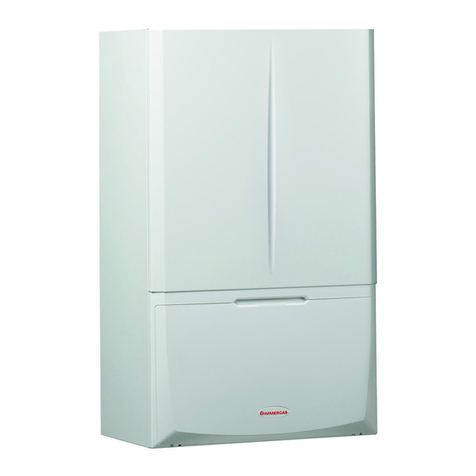
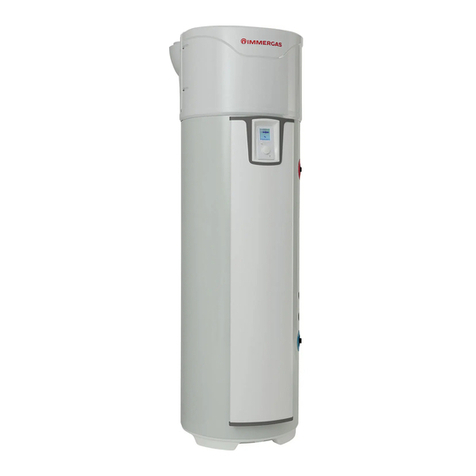
  9. Immergas VICTRIX HYBRID User manual

Immergas VICTRIX HYBRID User manual

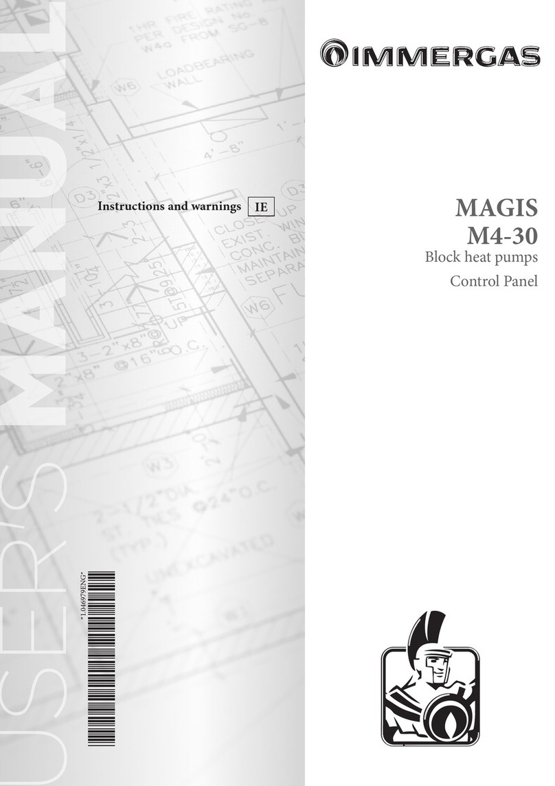
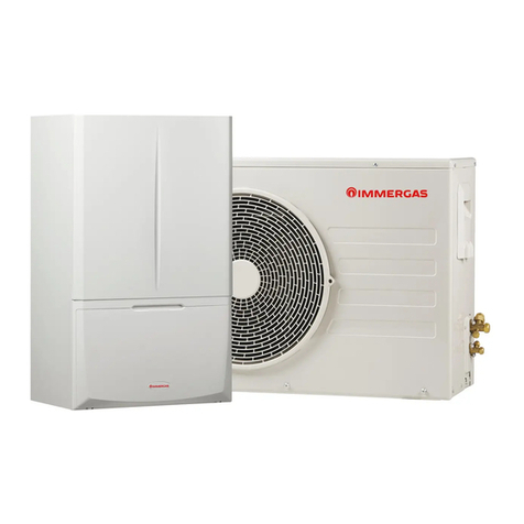
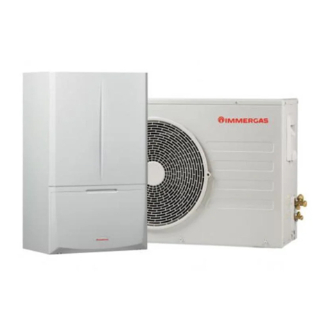
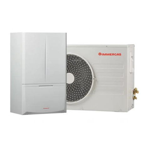
VICTRIX HYBRID
IE
Instruction booklet and
warning
Installer
User
Maintenance Technician
*1.046309ENG*
*1.046309ENG*
2
3
INDEX
Dear Customer,................................................................................. 4
General recommendations.............................................................. 4
Safety symbols used.......................................................................... 5
Personal protective equipment....................................................... 5
1 Installation............................................................................ 6
1.1 Description of the product................................................. 6
1.2 Indoor Unit Installation recommendations..................... 6
1.3 Victrix Hybrid Installation................................................. 9
1.4 Outdoor Unit Installation................................................. 14
1.5 Indoor Unit main dimensions. ........................................ 15
1.6 Minimum indoor Unit installation distances ................ 15
1.7 Installation of the outdoor unit in the recessed frame
(Optional)........................................................................... 16
1.8 Indoor unit connection Unit............................................ 17
1.9 Indoor Unit gas connection. ............................................ 17
1.10 Hydraulic connection........................................................ 18
1.11 Electrical power supply connection. ............................... 19
1.12 Control panel main dimensions. ..................................... 20
1.13 Control panel installation operations. ............................ 20
1.14 External temperature probe. ............................................ 20
1.15 room chrono-thermostats (Optional)............................. 21
1.16 230 VAC congurable outlet. ........................................... 21
1.17 Immergas ue systems...................................................... 22
1.18 Tables of resistance factors and equivalent lengths of
“green range” ue system components. .......................... 23
1.19 Outdoor installation in partially protected area............ 25
1.20 Internal installation using a recessed frame with
direct air intake. ................................................................. 27
1.21 Concentric horizontal kit installation............................. 28
1.22 Concentric vertical Kit installation. ................................ 30
1.23 Separator kit installation................................................... 32
1.24 Adaptor C9 kit installation............................................... 34
1.25 Ducting of ues or technical slots. .................................. 36
1.26 Conguration type B, open chamber and fan assisted
for indoors. ......................................................................... 37
1.27 Flue exhaust to ue/chimney............................................ 37
1.28 Flues, chimneys and chimney caps. ................................ 37
1.29 Water treatment system lling......................................... 38
1.30 System lling. ..................................................................... 38
1.31 Filling the condensate drain trap..................................... 38
1.32 Gas system start-up. .......................................................... 38
1.33 Commissioning of the combustion unit (Ignition)....... 39
1.34 Kits available on request. .................................................. 39
1.35 Circulation pump and load losses. .................................. 40
1.36 Indoor unit main components......................................... 42
2 Instructions for use and maintenance............................. 43
2.1 General warnings............................................................... 43
2.2 Cleaning and maintenance............................................... 44
2.3 Control panel...................................................................... 45
2.4 Operation overview. .......................................................... 45
2.5 Comfort / economy / manual operation......................... 46
2.6 Operation with external probe (Audax.DK4)................ 46
2.7 Clock and programs.......................................................... 46
2.8 Settings menu..................................................................... 47
2.9 Indoor Unit Control panel. .............................................. 50
2.10 Use of the indoor unit....................................................... 51
2.11 Indoor unit information menu........................................ 51
2.12 Faults and malfunctions signals from the Control
Panel. ................................................................................... 52
2.13 Switching o....................................................................... 57
2.14 Restore central heating system pressure......................... 57
2.15 Draining the system. ......................................................... 57
2.16 Emptying the D.H.W. circuit............................................ 57
2.18 Antifreeze protection. ....................................................... 57
2.19 Cleaning the case. .............................................................. 57
2.20 Decommissioning.............................................................. 57
3 Instructions for maintenance and
initial check. ....................................................................... 58
3.1 General warnings............................................................... 58
3.2 Initial check. ....................................................................... 58
3.3 Yearly Victrix Hybrid check and maintenance.............. 59
3.4 Indoor Unit Hydraulic Diagram...................................... 61
3.5 Indoor Unit Electrical Diagram....................................... 62
3.6 Programming Victrix Hybrid. ......................................... 63
3.7 Troubleshooting................................................................. 67
3.8 Converting the boiler to other types of gas.................... 67
3.9 Indoor unit fan revs number calibration........................ 67
3.10 Indoor Unit CO2adjustment............................................ 68
3.11 Checks following conversion to another type of gas..... 68
3.12 Programming the indoor unit P.C.B.. ............................. 69
3.13 Password-protected special functions............................. 72
3.14 Automatic vent function (dI)........................................... 72
3.15 Flue installation (Fu)......................................................... 72
3.16 Maintenance function (MA)............................................ 72
3.17 Screed heater function. ..................................................... 73
3.18 “Chimney sweep function”................................................73
3.19 Pump anti-block function. ............................................... 74
3.20 ree-way anti-block system............................................ 74
3.21 Radiators antifreeze function........................................... 74
3.22 Room anti-freeze function. .............................................. 74
3.23 Logic of operation.............................................................. 75
3.24 Indoor Unit casing disassembly....................................... 76
4 Technical data..................................................................... 78
4.1 Indoor Unit variable thermal output. ............................. 78
4.2 Combustion parameters. .................................................. 78
4.3 Indoor Unit Data Table..................................................... 79
4.4 Outdoor Unit technical data tables. ................................ 80
4.5 Product che (in compliance with Regulation
811/2013)............................................................................ 81
4.6 Parameters for lling in the package che. .................... 83
4
e manufacturer declines all liability due to printing or transcription errors, reserving the right to make any modications to its
technical and commercial documents without forewarning.
e company IMMERGAS S.p.A., with registered oce in via Cisa Ligure 95 42041 Brescello (RE), declares that the design, manu-
facturing and aer-sales assistance processes comply with the requirements of standard UNI EN ISO 9001:2015.
For further details on the product CE marking, request a copy of the Declaration of Conformity from the manufacturer, specifying the
appliance model and the language of the country.
Dear Customer,
Our compliments for having chosen a top-quality Immergas product, able to ensure well-being and safety for a long period of time. As
an Immergas customer you can also count on a Qualied Authorised Aer-Sales Technical Assistance Centre, prepared and updated to
guarantee constant eciency of your boiler. Read the following pages carefully: you will be able to draw useful tips on the correct use of the
device, compliance of which will conrm your satisfaction with the Immergas product.
For assistance and routine maintenance, contact Authorised Technical Service Centres: they have original spare parts and are specically
trained directly by the manufacturer.
GENERAL RECOMMENDATIONS
is book contains important information for the:
Installer (section 1); For the installation of the AUDAX.DK4 outdoor unit see the relevant instruction manual;
User (section 2);
Maintenance Technician (section 3).
• e user must carefully read the instructions in the specic section (section 2).
• e user must limit operations on the appliance only to those explicitly allowed in the specic section.
• e appliance must be installed by qualied and professionally trained personnel.
• e instruction booklet is an integral and essential part of the product and must be given to the new user in the case of transfer
or succession of ownership.
• It must be stored with care and consulted carefully, as all of the warnings provide important safety indications for installation,
use and maintenance stages.
• In compliance with the legislation in force, the systems must be designed by qualied professionals, within the dimensional limits
established by the Law. Installation and maintenance must be performed in compliance with the regulations in force, according
to the manufacturer's instructions and by professionally qualied sta, meaning sta with specic technical skills in the plant
sector, as provided for by Law.
• Improper installation or assembly of the Immergas device and/or components, accessories, kits and devices can cause unexpected
problems for people, animals and objects. Read the instructions provided with the product carefully to ensure proper installation.
• is instructions manual provides technical information for installing Immergas products. As for the other issues related to the
installation of products (e.g. safety at the workplace, environmental protection, accident prevention), it is necessary to comply
with the provisions of the standards in force and the principles of good practice.
• All Immergas products are protected with suitable transport packaging.
• e material must be stored in a dry place protected from the weather.
• Damaged products must not be installed.
• Maintenance must be carried out by skilled technical sta. For example, the Authorised Immergas Service Centre that represents
a guarantee of qualications and professionalism.
• e device must only be destined for the use for which it has been expressly declared. Any other use will be considered improper
and therefore potentially dangerous.
• If errors occur during installation, operation and maintenance, due to non-compliance with technical laws in force, standards or
instructions contained in this booklet (or however supplied by the manufacturer), the manufacturer is excluded from any con-
tractual and extra-contractual liability for any damages and the device warranty is invalidated.
5
SAFETY SYMBOLS USED.
GENERIC HAZARD
Strictly follow all of the indications next to the pictogram. Failure to follow the indications can generate hazard situa-
tions resulting in possible harm to the health of the operator and user in general.
ELECTRICAL HAZARD
Strictly follow all of the indications next to the pictogram. e symbol indicates the appliance’s electrical components
or, in this manual, identies actions that can cause an electrical hazard.
MOVING PARTS
e symbol indicates the appliance’s moving components that can cause hazards.
HOT SURFACES
e symbol indicates the appliance’s very hot components that can cause burns.
SHARP SURFACES
e symbol indicates the appliance’s components or parts that can cause cuts if touched.
EARTH TERMINAL CONNECTION
e symbol identies the appliance’s earth terminal connection point.
READ AND UNDERSTAND THE INSTRUCTIONS
Read and understand the appliance’s instructions before performing any operation, carefully following the indications
provided.
INFORMATION
Indicates useful tips or additional information.
SAFETY GLOVES
PERSONAL PROTECTIVE EQUIPMENT.
SAFETY GOGGLES
SAFETY FOOTWEAR
e user must not dispose of the appliance at the end of its service life as municipal waste, but send it to appro-
priate collection centres.

Other Immergas Heat Pump manuals

Immergas AUDAX PRO 4 V2 Product manual

Immergas

Immergas AUDAX PRO 4 V2 Product manual

Immergas Magis M 4 EH3 Technical manual

Immergas

Immergas Magis M 4 EH3 Technical manual

Immergas MAGIS HERCULES PRO MINI 6 Operating instructions

Immergas

Immergas MAGIS HERCULES PRO MINI 6 Operating instructions

Immergas TRIO PACK HYBRID 4 Product manual

Immergas

Immergas TRIO PACK HYBRID 4 Product manual

Immergas MAGIS PRO Series Operating instructions

Immergas

Immergas MAGIS PRO Series Operating instructions

Immergas MAGIS M 4 Product manual

Immergas

Immergas MAGIS M 4 Product manual

Immergas MAGIS COMBO PLUS V2 Series Operating instructions

Immergas

Immergas MAGIS COMBO PLUS V2 Series Operating instructions

Immergas AUDAX TOP ErP Series User manual

Immergas

Immergas AUDAX TOP ErP Series User manual

Immergas MAGIC COMBO PLUS Series Product manual

Immergas

Immergas MAGIC COMBO PLUS Series Product manual

Immergas MAGIS HERCULES PRO 4 Operating instructions

Immergas

Immergas MAGIS HERCULES PRO 4 Operating instructions

Immergas AUDAX TOP 21 ErP Operating instructions

Immergas

Immergas AUDAX TOP 21 ErP Operating instructions

Immergas MAGIS COMBO PLUS 5 Product manual

Immergas

Immergas MAGIS COMBO PLUS 5 Product manual

Immergas MAGIS COMBO PLUS Series Product manual

Immergas

Immergas MAGIS COMBO PLUS Series Product manual

Immergas 3.023355 User manual

Immergas

Immergas 3.023355 User manual

Immergas TRIO PACK ELECTRIC 4 Product manual

Immergas

Immergas TRIO PACK ELECTRIC 4 Product manual

Immergas MAGIS COMBO Product manual

Immergas

Immergas MAGIS COMBO Product manual

Immergas HYDRO 3 Product manual

Immergas

Immergas HYDRO 3 Product manual

Immergas AUDAX PRO 5 Operating instructions

Immergas

Immergas AUDAX PRO 5 Operating instructions

Immergas IMMERWATER 190S V5 Product manual

Immergas

Immergas IMMERWATER 190S V5 Product manual

Immergas MAGIS COMBO 4 V2 Operating instructions

Immergas

Immergas MAGIS COMBO 4 V2 Operating instructions

Immergas AUDAX TOP 6 ErP Operating instructions

Immergas

Immergas AUDAX TOP 6 ErP Operating instructions

Immergas RAPAX 300 ERP User manual

Immergas

Immergas RAPAX 300 ERP User manual

Immergas Magis Combo 5 Product manual

Immergas

Immergas Magis Combo 5 Product manual

Immergas Magis Combo Series Product manual

Immergas

Immergas Magis Combo Series Product manual

Popular Heat Pump manuals by other brands

Daikin RXL12QMVJU Service manual

Daikin

Daikin RXL12QMVJU Service manual

AIREDALE BluCube CUR092V16-1CO-0 Installation and maintenance manual

AIREDALE

AIREDALE BluCube CUR092V16-1CO-0 Installation and maintenance manual

Calyenty RBH 125 Customer's manual

Calyenty

Calyenty RBH 125 Customer's manual

GRE HPGI50 owner's manual

GRE

GRE HPGI50 owner's manual

Carrier 30XW Installation, operation and maintenance instructions

Carrier

Carrier 30XW Installation, operation and maintenance instructions

Hayward SUMHEAT HP5131DT3 Installation instructions manual

Hayward

Hayward SUMHEAT HP5131DT3 Installation instructions manual

REMKO SQW 400 Electrical wiring

REMKO

REMKO SQW 400 Electrical wiring

Sanyo SAP120FCH Service manual

Sanyo

Sanyo SAP120FCH Service manual

Daikin EHYHBH05AA Operation manual

Daikin

Daikin EHYHBH05AA Operation manual

Panasonic WH-SDF03E3E5 Design handbook

Panasonic

Panasonic WH-SDF03E3E5 Design handbook

Airxcel 45000 Series Installation, operation and maintenance instructions

Airxcel

Airxcel 45000 Series Installation, operation and maintenance instructions

Mitsubishi Electric PUZ-SWM60VAA Service manual

Mitsubishi Electric

Mitsubishi Electric PUZ-SWM60VAA Service manual

Dimplex LI 16I-TUR Installation and operating instruction

Dimplex

Dimplex LI 16I-TUR Installation and operating instruction

Carrier WSHP Open v3 Integration guide

Carrier

Carrier WSHP Open v3 Integration guide

Mitsubishi Electric EHSE-YM9EC Service manual

Mitsubishi Electric

Mitsubishi Electric EHSE-YM9EC Service manual

TGM CTV14CN018A Technical manual

TGM

TGM CTV14CN018A Technical manual

Carrier 38MGQ Series installation instructions

Carrier

Carrier 38MGQ Series installation instructions

Kokido K2O K880BX/EU Owner's manual & installation guide

Kokido

Kokido K2O K880BX/EU Owner's manual & installation guide

manuals.online logo
manuals.online logoBrands
  • About & Mission
  • Contact us
  • Privacy Policy
  • Terms and Conditions

Copyright 2025 Manuals.Online. All Rights Reserved.