manuals.online logo
Brands
  1. Home
  2. •
  3. Brands
  4. •
  5. Immergas
  6. •
  7. Heat Pump
  8. •
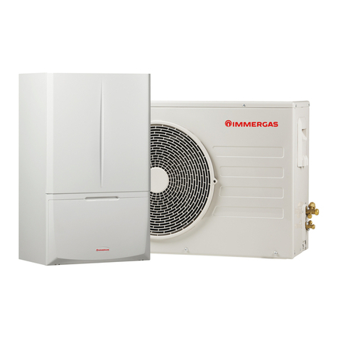
  9. Immergas MAGIS HERCULES PRO 4 Operating instructions

Immergas MAGIS HERCULES PRO 4 Operating instructions

Instructionsandrecommendations
Installer
User
Maintenancetechnician
*1.045472ENG*

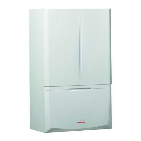
IE MAGISHERCULES
PRO469
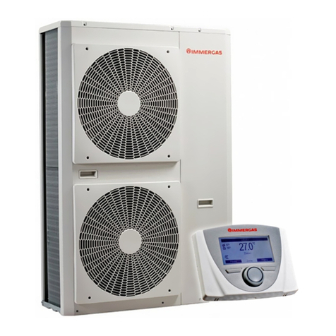
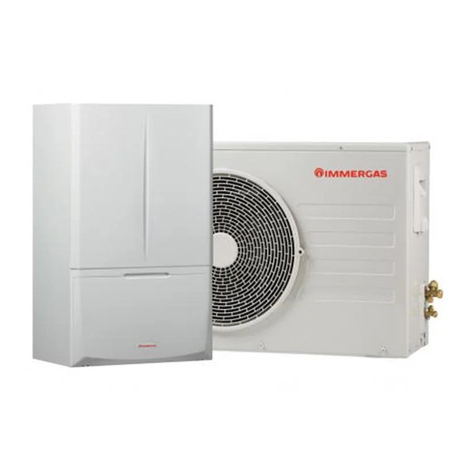
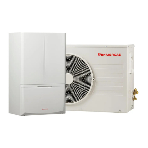
Heatpump consistingof:
-indoorunit
UIMHPBP
-outdoorcondensingunit
AUDAX PRO4 -6- 9V2
2
3
INDEX
Dear Customer.................................................................................. 4
Safety symbols used.......................................................................... 6
Personal protective equipment ....................................................... 6
1 Installing the indoor unit............................................... 7
1.1 Description of the product.................................................... 7
1.2 Installation warnings.............................................................. 7
1.3 Indoor unit main dimensions............................................. 10
1.4 Minimum indoor unit installation distances.................... 11
1.5 Indoor unit hydraulic connection...................................... 12
1.6 Connecting the chiller line.................................................. 12
1.7 Electrical connection ........................................................... 12
1.8 Remote zone control (Optional) ........................................ 18
1.9 MODBUS temperature and humidity room probes
(Optional).............................................................................. 18
1.10 Room chrono-thermostats (Optional) .............................. 19
1.11 Humidistat ON/OFF (Optional) ........................................ 20
1.12 External temperature probe (Optional) ............................ 20
1.13 Temperature control setting................................................ 21
1.14 System lling......................................................................... 22
1.15 Operating limits.................................................................... 22
1.16 Indoor unit start-up (ignition) ........................................... 23
1.17 Circulation pump ................................................................. 23
1.18 Domestic hot water storage tank unit................................ 29
1.19 Kits available on request ...................................................... 30
1.20 Main components................................................................. 31
2 Instructions for use and maintenance ......................... 32
2.1 General recommendations.................................................. 32
2.2 Cleaning and maintenance.................................................. 34
2.3 Control panel ........................................................................ 34
2.4 System use ............................................................................. 35
2.5 Operating mode.................................................................... 36
2.6 Parameters and information menu .................................... 41
2.7 Fault and anomaly signals ................................................... 55
2.8 Restore central heating system pressure............................ 63
2.9 Draining the system ............................................................. 63
2.10 Emptying the D.H.W. circuit............................................... 63
2.11 Storage tank draining........................................................... 63
2.12 Cleaning the case.................................................................. 63
2.13 Permanent shutdown ........................................................... 63
3 Instructions for maintenance and initial check...........64
3.1 General recommendations.................................................. 64
3.2 Initial check........................................................................... 64
3.3 Yearly appliance check and maintenance.......................... 65
3.4 Finned air coil maintenance................................................ 65
3.5 Hydraulic diagram................................................................ 66
3.6 Wiring diagram..................................................................... 67
3.7 System lter........................................................................... 75
3.8 Troubleshooting.................................................................... 75
3.9 P.C.B. programming............................................................. 76
3.10 First ignition parameter setting.......................................... 87
3.11 DHW (Domestic hot water) BOOST function ................ 88
3.12 Anti-Legionella function..................................................... 88
3.13 DHW recirculation function .............................................. 88
3.14 Pump anti-block function................................................... 88
3.15 ree-way anti-block system .............................................. 88
3.16 System setpoint correction function.................................. 89
3.17 Photovoltaic function........................................................... 89
3.18 Integration with the system electrical resistances............ 89
3.19 Zone 2/3 safety thermostat function.................................. 89
3.20 Conjunction Mode ............................................................... 89
3.21 Heat pump disabling function............................................ 90
3.22 Diverter valve management (summer / winter)............... 90
3.23 External probe setting.......................................................... 90
3.24 Manual drives........................................................................ 90
3.25 Outdoor condensing unit test mode function.................. 90
3.26 Outdoor Condensing Unit Pump Down Function.......... 90
3.27 Supervision device conguration....................................... 90
3.28 Casing removal ..................................................................... 91
3.29 Indoor unit separation......................................................... 98
4 Technical data............................................................. 102
4.1 Technical data table............................................................ 102
4.2 Magis Hercules Pro 4 product che (in compliance
with Regulation 811/2013)................................................ 104
4.3 Magis Hercules Pro 6 product che (in compliance
with Regulation 811/2013)................................................ 107
4.4 Magis Hercules Pro 9 product che (in compliance
with Regulation 811/2013)................................................ 110
4.5 Parameters for lling in the package che ...................... 113
4
DearCustomer
Congratulations for having chosen a top-qualityImmergas product, able to assure well-being and safetyfor a longperiodof time.AsanIm-
mergascustomeryou can alsocount ona Qualied AuthorisedAer-SalesTechnicalAssistanceCentre, preparedandupdatedto guarantee
con stant e ciency of your appliance. Read the follow ing pages carefully: you will be able to draw usef ul tips on the proper u se of the device,
com p l i an c e w it h wh i c h w i l l c o n r m yo u r s a t i s f a c t i o n w i th t h e Im m e r g a s p r o du c t .
For assistance and routine maintenance, contact Authorised Technical Service Centres: they have original spare parts and are specically
traineddirectlybythe manufacturer.
ermal systems must undergo periodic maintenance and scheduled checks of the energy eciency in compliance with national,
regionalor localprovisionsinforce.
e company IMMERGASS.p.A., with registered oce in via Cisa Ligure 95 42041 Brescello (RE), declares that the design, manufac-
turing andaer-salesassistance processes complywiththe requirementsof standard UNIEN ISO9001:2015.
For further details on the product CE marking, request a copy of the Declaration of Conformity from the manufacturer, specifying the
appliance model andthelanguageof thecountry.
e manufacturer declines all liability due to printing or transcription errors, reserving the right to make any modications to its tech-
nicalandcommercialdocuments withoutforewarning.
5
GENERALRECOMMENDATIONS
isbookcontains importantinformationforthe:
Installer(section 1);
User (section 2);
MaintenanceTechnician(section 3).
• eusermustcarefully read theinstructionsin thespecicsection(section2).
• eusermustlimitoperationsonthe appliance only tothoseexplicitly allowedinthespecic section.
• Every operationcarried outontheheatpump(e.g. set up,inspection,installationandcommissioning),mustmandato-
rily be performed by authorised personnel alone and in possession of a technical engineering or professional degree
qualifying them to perform these tasks. ey must also have attended a refresher course acknowledged by competent
authorities.isparticularlyapplies topersonalspecialisedinC.H.andair-conditioningsystems andqualiedelectri-
cians who, due to their specialised training, skills and experience are experts in the correct installation and mainte-
nanceofC.H.,coolingandair-conditioningsystems.
• eappliancemust be installedbyqualied andprofessionally trainedpersonnel.
• einstructionbooklet is anintegral andessentialpartof theproductandmustbe giventothenew userinthecase oftransfer
orsuccession of ownership.
• It must be stored with care and consulted carefully, as all of the warnings provide important safety indications for installa-
tion,use andmaintenancestages.
• In compliance with the legislation in force, the systems must be designed by qualied professionals, within the dimensional
limits established by the Law. Installation and maintenance must be performed in compliance with the regulations in force,
accordingto themanufacturer'sinstructionsandbyprofessionally qualiedsta,meaningstawithspecic technicalskills
in theplantsector,asprovided forby Law.
• Improperinstallationorassembly oftheImmergas deviceand/orcomponents, accessories,kits anddevicescancause unex-
pected problemsforpeople,animals andobjects. Read theinstructionsprovided withtheproductcarefullytoensureproper
installation.
• isinstructionsmanualprovidestechnicalinformationforinstalling Immergas products.As fortheotherissues related to
the installation of products (e.g. safety at the workplace, environmental protection, accident prevention), it is necessary to
complywith theprovisionsofthestandardsinforceandtheprinciples ofgoodpractice.
• All Immergasproductsareprotected withsuitabletransportpackaging.
• ematerialmust be storedina dryplace protectedfromtheweather.
• Damagedproductsmust notbe installed.
• Maintenance must be carried out by skilled technical sta. For example, the Authorised Service Centre that represents a
guaranteeofqualications andprofessionalism.
• e appliance must only be destined for the use for which it has been expressly declared. Any other use will be considered
improperandthereforepotentiallydangerous.
• If errors occur during installation, operation and maintenance, due to non-compliance with technical laws in force, stand-
a rd s or i n s t r u c t io ns co nt a i ne d i n t h i s b o ok le t (or howe ve r s up pl ie d by t h e ma nu fa c t u r er), t h e m a n u f a c t u re r i s e x clud e d f rom
anycontractualandextra-contractualliabilityforanydamagesandthedevicewarranty is invalidated.
• In theeventofmalfunctions, faultsor incorrect operation,turn theapplianceoandcontactanauthorisedcompany(e.g.the
Authorised Technical Assistance Centre, which has specically trained sta and original spare parts). Do not attempt to
modifyor repair theappliancealone.
6
SAFETYSYMBOLS USED
GENERICHAZARD
Strictly follow all of the indications next to the pictogram. Failure to follow the indications can generate hazard situations
re s u lt i ng i n p o s si bl e h a r m to t he h e a lt h of t he o p er at or a nd u s e r i n g en e r a l, a nd /or pro pe r t y d a ma ge .
ELECTRICALHAZARD
Strictly followall oftheindicationsnext tothepictogram. esymbolindicatestheappliance’selectrical componentsor,in
this manual,identiesactionsthatcan causeanelectrical hazard.
WARNINGFOR INSTALLER
Read theinstructionbooklet carefullybeforeinstallingtheproduct.
LOWFLAMMABILITYMATERIAL
esymbolindicatesthat theappliance containslowammabilitymaterial.
WAR N INGS
Strictly follow all of the indications next to the pictogram. Failure to follow the indications can generate hazard situations
re s u lt i ng i n p o s si bl e m i nor i nju r ie s to t he h e a lt h of b o t h t h e op e r at or a nd t h e u s er i n ge ne r a l , a n d /o r s l i g ht ma ter ia l d a m a ge .
ATTENTION
Read and understand the instructions of the appliance before carrying out any operation, carefully following the instruc-
tions given.Failuretoobservetheinstructions mayresultinmalfunctionoftheunit.
INFORMATION
Indicatesusefultipsoradditionalinformation.
EARTHTERMINALCONNECTION
esymbolidenties theappliance’searthterminal connectionpoint.
DISPOSAL WARNING
e user must not dispose of the appliance at the end of its service life as municipal waste, but send it to appropriate
collectioncentres.
PERSONALPROTECTIVEEQUIPMENT
SAFETYGLOVES
EYEPROTECTION
SAFETYFOOTWEAR
7
INSTALLER
USERMAINTENANCETECHNICIAN
TECHNICALDATA
1INSTALLINGTHEINDOORUNIT
1.1 DESCRIPTIONOFTHEPRODUCT.
Magis HerculesPro 4-6-9isa heat pump consistingof:
- UI MHP BP indoor unit (hereinaer called, indoor unit or UI
MHP).
- Audax Pro 4-6-9 V2 outdoor condensing unit (hereinaer re-
ferred toasoutdoorcondensing unit orAudax Pro 4-6-9V2).
Magis Hercules Pro 4-6-9 is perfectly operational only if the two
units arecorrectlypowered andinterconnected.
eUI MHPindoorunit wasdesigned solelyforoorinstallation
for heating and air conditioning and to produce domestic hot wa-
terfordomestic useandsimilarpurposes.
For normal operation is must be paired with one of the following
outdoorcondensingunits:
- AudaxPro4V2outdoor condensing unit;
- AudaxPro6V2outdoor condensing unit;
- AudaxPro9V2outdoor condensing unit;
Accordingly, it is necessary to comply with all of the rules regard-
ing safety andtheuseof bothappliances.
1.2 INSTALLATIONWARNINGS
Operatorswhoinstallandservicetheap-
pliance must wear the personal protec-
tive equipment required by applicable
law.
e place of installation of the appliance and relative
Im mer ga s ac c e ss or ie s mu st have su it abl e feat u re s (t ec h-
nical and structural), such as to allow for (always in safe,
ecientandcomfortableconditions):
- installation (according to the provisions of technical
legislationandtechnical regulations);
- maintenance operations (including scheduled, peri-
odic,routineandspecialmaintenance);
- removal (to outdoors in the place for loading and
transporting the appliances and components) as well
as the eventual replacement of those with appliances
and/orequivalentcomponents.
Installation must be carried out according to regulation
standards, current legislation and in compliance with
local technical regulations and the required technical
procedures.
e appliance operates with R32 refrig-
erantgas.
isgasisODOURLESS.
Paytheutmostattention
Strictlyfollowtheinstructionhandbook
oftheoutdoorcondensingunitbeforein-
stallation and any type of operation on
thecoolingline.
R32 refrigerant gas belongs to the low
ammability refrigerant category: class
A2L according to standard ISO 817. It
guarantees high performance with low
environmental impact. e new gas re-
duces the potential environmental im-
pact by one third compared to R410A,
having less eect on global warning
(GWP 675).
e manufacturer declines all liability in the event of
damage caused by appliances removed from other sys-
tems orforanynon-conformities withsuch equipment.
8
INSTALLER
USERMAINTENANCETECHNICIAN
TECHNICALDATA
Only a professionally enabled company is authorised to
install Immergas appliances.
Check the environmental operating conditions of all
partsrelevantto installation,referring to this booklet.
If installing akit orservicing theappliance,alwaysemp-
tythesystem’sdomestichotwater circuitrstsoas notto
compromise the appliance’s electrical safety (Par-
ag. 2.9).
Always disconnect the appliance from voltage and, de-
pending on the type of operation, decrease the pressure
and/orbringitto zero inthegasandDHWcircuits.
Beforeinstalling the appliance,ensurethatit isdelivered
in perfect condition; if in doubt, contact the supplier
immediately.
Packing materials (staples, nails, plastic bags, polysty-
renefoam,etc.)constitutea hazardandmust be keptout
ofthereach ofchildren.
If the appliance is installed inside or between cabinets,
ensure sucient space for routine servicing; for mini-
muminstallationdistances, seeFig. 2.
Keep allammable objectsawayfromtheappliance(pa-
per,rags, plastic,polystyrene,etc.).
Any modication to the appliance that is not explicitly
indicatedinthissectionofthebookletisforbidden.
Installationstandards
is indoor unit must be installed in an environment in
which thetemperaturecannotfallbelow0°C.
Donotexposethe indoor unitto atmosphericagents.
is type of installation is possible when permitted by
the laws in force in the appliance's country of destina-
tion.
Do not install in places/rooms that con-
stitute public areas of apartment build-
ings, internal stairways or other escape
routes (e.g. oor landings, entrance
halls,etc.).
Topreventelectrocution,reorinjury,al-
ways switch o the unit, disable the pro-
tective switch and, if smoke escapes or if
the unit is extremely noisy, contact the
Authorised Aer-Sales Technical Assis-
tanceCentre.
Donot installin placeswherethere is the
riskofcombustiblegasescaping.
Donotinstallnearsourcesofheat.
9
INSTALLER
USERMAINTENANCETECHNICIAN
TECHNICALDATA
Pay attention not to generate sparks as
follows:
– Do not remove the fuses while the unit
ison.
– Donotunplugtheunitwhileitison.
It is recommended to install the outlet
high up. Lay the cables in such a way that
theydonotgettangled.
is indoor unit is used to heat water to below boiling
temperatureinatmosphericpressure.
ey must be connected to a central heating system and
domestic hot water circuit suited to their performance
andcapacity.
e appliance is built to also operate in
coolingmode.
If cold water production, during sum-
mer,couldinterfereanddamagethecen-
tral heating onlysystems, necessary pre-
caut ions must be ta ken to pre vent t hat a n
unintentional production of cold water
enterstheheatingonlysystem.
Failure to comply with the above implies
personal responsibility and invalidates
thewarranty.
“Anti-legionella”thermaltreatmentoftheaccumulation
storagetank.
eanti-Legionellafunctionisprogrammed directlyon
thecontrol panel.
During this phase, the temperature of the water inside the tank
exc e e d s 6 0 ° C w it h t he s ub s e q ue nt r i sk o f bu r n s .
Keep this domestic hot water treatment under control (and in-
form the users) to prevent unforeseeable damage to people, ani-
mals, things.
If required install a thermostatic valve on the domestic hot water
outlet to prevent scalding.
10
INSTALLER
USERMAINTENANCETECHNICIAN
TECHNICALDATA
1.3 INDOORUNITMAINDIMENSIONS
1
Key (Fig. 1):
RP - Return tosolar panels(optional)
MP - Flow from solar panels(optional)
RZ3 - Mixed zone 3 system return (optional)
MZ3 - Mixed zone3 systemow(optional)
RZ2 - Mixed zone 2system return (optional)
MZ2 - Mixedzone2system ow(optional)
RZ1 - Direct zone1 systemreturn
MZ1 - Directzone 1 systemow
AC - Domestichot wateroutlet
AF - DHW (Domestic hotwater)waterinlet
RC - Pump (optional)
SC - Discharge any condensate collected in the tray
LP - Chiller line- liquid phase
GP - Chiller line -gaseous phase
V1 - 3rd zoneelectricalconnections
V2 - Additional resistance powersupplyelectrical connections
V3 - Power supply cable electricalconnections
V4 - Mainelectricalconnections
Height
(mm)
Width
(mm)
Depth
(mm)
1970 650 916
CONNECTIONS
CHILLER
LINE
D.H.W. RECIRCULA-
TION SYSTEM
LP GP AC- AF RC RP- MP RZ1-MZ1 RZ2-MZ2 RZ3- MZ3
SAE1/4” SAE5/8” G3/4" G3/4" G3/4" G1" G1" G1"
11
INSTALLER
USERMAINTENANCETECHNICIAN
TECHNICALDATA
1.4 MINIMUMINDOORUNITINSTALLATIONDISTANCES
2
Key (Fig. 2):
A - 500 mm
B - 200 mm
C - 30 mm
D - 400mm
E - 10mm
12
INSTALLER
USERMAINTENANCETECHNICIAN
TECHNICALDATA
1.5 INDOOR UNIT HYDRAULIC
CONNECTION
3and8barsafetyvalve
e a pp l i a nc e s a fe t y v a lv e s out l e t mu s t b e c on n e c t e d to a
drainingfunnel.
Otherwise, the appliance’s manufacturer declines any
responsibilityincase ofoodingifthe drain valvescut.
A treatment of the heating and water system water is required, in
compliance with the technical standards in force, in order to pro-
tect the system and the appliance from deposits (e.g. scale), slurry
orotherhazardousdeposits.
Water connections must be made in a rational way using the cou-
plingson theindoor unit template.
e manufacturer declines all liability in the event of
d a ma g e c au sed by t he i ns t a l l at io n of a n aut om at ic  l l i ng
system.
In order to meet the system requirements established by EN 1717
in terms of pollution of drinking water, we recommend installing
t h e I M M E RG A S a nt i -b a c k ow k it to b e u se d u p st rea m o f t h e c ol d
water inlet connection of the indoor unit. We also recommend
usingcategory 2 heattransfer uid(ex:water+ glycol) in theinter-
nal unit primary circuit (heating and/or cooling circuit), as de-
 n ed i n s t a nd a rd E N 1717.
Topreservethedurationof appliance eciencyfeatures,
in the presence of water whose features can lead to the
deposit of lime scale, installation of the “polyphosphate
dispenser” kitis recommended.
1.6 CONNECTINGTHECHILLERLINE
As far as connecting the chiller line is concerned, all the instruc-
tions contained in the outdoor condensing unit instructions
bookletmustbefollowed.
Maketheconnectionsdirectlyontheindoorunitcouplings.
1.7 ELECTRICALCONNECTION
Indoorunitelectricalconnection
e internal unit has an IPX5D degree of protection; electrical
safety of the appliance is achieved only when it is properly con-
nectedto anecientearthingsystem, as speciedbycurrentsafe-
tystandards.
e manufacturer declines any responsibility for dam-
age or physical injury caused by failure to connect the
indoor unit to an ecient earthing system or failure to
complywith theIECreferencestandards.
Connectionsareprovidedbothto thecontrolpanel(Fig. 6)andto
themain panel(Fig. 7).
13
INSTALLER
USERMAINTENANCETECHNICIAN
TECHNICALDATA
Mainpanelopening(Fig. 3).
Toopen themainpanel,simplyfollowtheinstructionsbelow:
1. Removethe aesthetic prole.
2. Disassemble thelowerfront.
3. Loosen thescrews(a)
4. Remove the main panelcover (b).
Ensure that the electrical installation corresponds to maximum
absorbed power specications as shown on the indoor unit data
nameplate.
Indoor units are supplied complete with an “X” type power cable
(c) without plug.
e power supply cable must be connect-
ed to a 230V ±10% / 50Hz mains supply
respecting L-N polarity and earth con-
nection; this network must also have a
multi-pole circuit breaker with class III
overvoltage category in compliance with
installationregulations.
To protect from possible dispersions of
DC voltage, it is necessary to provide a
typeAdierentialsafetydevice.
If the power supply cable is damaged, it
must be replaced by a special cable or as-
sembly,whichareonlyavailablefromthe
manufacturer or its Authorised Af-
ter-SalesTechnicalAssistanceCentre.
It is recommended to contact a qualied
company (e.g. the Authorised Af-
ter-Sales Technical Assistance Centre)
forreplacementtoavoidahazard.
epowercablemustbe laidasshown (Fig. 3).
If thefusesonthecircuitboards need tobereplaced,thismust also
bedonebyqualiedpersonnel.
e appliance is equipped with two fuses: one 3.15A rapid 230 V
fuse andone10 Arapid230V fuseforintegrativeresistance.
For the main power supply to the appliance, never use adapters,
multiplesocketsorextensionleads.
a
b
a
a
a
c
3
14
INSTALLER
USERMAINTENANCETECHNICIAN
TECHNICALDATA
Electrical connectionstothemainpanel
eelectrical connectionsavailableare:
• Zone 1owprobe;
• Zone 2owprobe;
• Dehumidier Zone2;
• Zone 2humidistat;
• Zone 2thermostat;
• DHW recirculationprobe;
• Optional DHW (Domestichotwater)integrativeresistances;
• Optionalsystem integrativeresistances;
• Recirculationpump;
• Zone 2pump;
• Zone2 MixingValve.
e connection cables must follow the predetermined path using
thespecialcableglands(a)(Fig. 4).
Key (Fig. 4):
1 - ree-wayconnection(M30)
2 - Pump connection (M1)
3 - Return probeconnection (B5)
4 - Flowprobeconnection(B1)
5 - Liquidphaseprobe(B29)
6 - Zone1pump connection (M10-1)
7 - Flowmeter connection(B25)
8 - DHW probeconnection(B2)
9 - DHW (Domestic hotwater)resistanceconnection(E15-A)
a - Cable gland
2
1
3
4
5
6
7
8
9
a
4
15
INSTALLER
USERMAINTENANCETECHNICIAN
TECHNICALDATA
Openthecontrolpanelconnectionscompartment(Fig. 5).
To carry out electrical connections, all you have to do is open the
connectionscompartmentas follows.
1. Removethe coverandtheaestheticprole.
2. Disassemble thecover.
3. Loosen thescrews(a).
4. Removethe cover(b)from thecontrol panel(c).
Atthispoint,you canaccessthe terminalboard.
Electricalconnectionstothecontrolpanel
eelectrical connectionsavailableare:
• Photovoltaicsystem:connectingtheproducttoaphotovoltaic
system enhances use of the outdoor condensing unit when the
photovoltaic panels areoperating.
• Dehumidier zone1.
• Summer/winterdiverter.
• Multifunctionrelay.
• Zone 1humidistat andthermostat.
• Zone 1, 2,3 remote devices (Zone remotepanel,Temperature/
humidityprobe,Dominus).
• Externalprobe
• Heatpumpdisabling.
Make the various electrical connections according to your needs
(Fig. 6).
Outdoorcondensing unitelectricalconnection
e i ndoo r u n it mu s t b e c ou pl e d to a n ou td o or c on d en s i n g u n it by
connecting terminals F1 and F2 as shown in the wiring diagram
(Fig. 7). e outdoor unit is powered at 230 V, regardless of the in-
door unit.
Congure the "HP model" parameter as indicated in paragraph
(Par. 3.9) depending on the type of connected outdoor condens-
ing unit.
1
1
1
a
a
ab
d
d
c
2
5
16
INSTALLER
USERMAINTENANCETECHNICIAN
TECHNICALDATA
Controlpanelconnectiondiagram
12
3
3
6
Key (Fig. 6):
A16-1 - Zone1dehumidier (optional)
A23 - Outdoor condensing unit
A32-1,2,3 - Zone 1,2,3remotepanel (optional)
A30 - Dominus (optional)
B4 - Externalprobe
K70 - Multifunction relay (optional)
M52 - Summer/winterdiverter(optional)
S20-1 - Zone1room thermostat (optional)
S36-1 - Zone1humidistat(optional)
S39 - Photovoltaicinlet(optional)
S42-1 - Zone1dehumidieralarm(optional)
S43 - Pdcdisablingselector(optional)
X40-1 - Zone 1 roomthermostat jumper
1 - Valvewith spring return
2 - 2-point valve
3 - Open/Closed
17
INSTALLER
USERMAINTENANCETECHNICIAN
TECHNICALDATA
Mainpanelconnectionboard
1
2
3
7
Key (Fig. 7):
A16-2 - Zone2dehumidier (optional)
B3-1 - Zone1owprobe(optional)
B3-2 - Zone2owprobe(optional)
B32 - Recirculation Probe
E15-B1,-B2 - SecondaryDHW integrationresistance(optional)
E16-A1,-A2 - System integrativeresistance (optional)
K15-B1,B2 - SecondaryDHW integration resistance relay (optional)
K16-A1,A2 - Systemintegrativeresistancerelay (optional)
M4 - DHW recirculation pump(optional)
M10-2 - Zone2circulator pump(optional)
M31-2 - Zone2mixing valve(optional)
S20-2 - Zone2room thermostat (optional)
S36-2 - Zone2humidistat(optional)
S42-2 - Zone2dehumidieralarm(optional)
1 - Closed
2 - Common
3 - Open
18
INSTALLER
USERMAINTENANCETECHNICIAN
TECHNICALDATA
1.8 REMOTEZONE CONTROLOPTIONAL
is remote device is used to adjust the setpoints and to view the
maininformationof thezonewhereitwascongured.
Connect theappliance asshown (Fig. 6).
To correctly congure the device, set the parameters as described
below:
AssistanceMenu->Deviceconguration
Sl ave a d d re s s : Ad d r e s s t o c on  g u r e a c c o r d i ng t o
thezone wherethedeviceis installed
Zone 1= 41
Zone 2= 42
Zone 3= 43
BaudRate 9600
Paritybit Even
Stopbits 1
Heat pump control NO
128
99
37
8
1.9 MODBUSTEMPERATURE AND
HUMIDITYROOMPROBESOPTIONAL
e Mo d bu s te mp e r a t u re a nd hu m id it y pr ob e i s u s e d t o d e te c t t he
roomtemperatureandhumidityandto calculatethedewpoint.
In addition, by setting the relative zone room setpoints available
on the Control panel (see Par. 2.6), it is possible to check the tem-
perature andhumidity ofa room.
Connect theappliance asshown (Fig. 6);
DIP-Switchcongurationtable
ON
123 4567 8
DIP 1-5 DIP 6-7 DIP 8
DIP1-5
(Address)
ON
123 45
Zone1
(Address
131)
ON
123 45
Zone2
(Address
132)
ON
123 45
Zone3
(Address
133)
DIP6-7
(Type)
ON
67
Modbus 1- 8
-E- 1
DIP8
(Speed)
ON
8
9600 bit/s
19
INSTALLER
USERMAINTENANCETECHNICIAN
TECHNICALDATA
1.10 ROOM CHRONOTHERMOSTATS
OPTIONAL
e indoor unit is prepared for the application of room
chrono-thermostats,whichareavailable as optional kits (Fig. 6).
A maximum of 3 temperature controllers can be applied directly
tothe appliance.
All Immergas chrono-thermostats are connected with 2 wires
only.
Carefully read the user and assembly instructions contained in
theaccessory kit.
Disconnect power to the unit before
makinganyelectricalconnections.
On/O Immergasdigital chrono-thermostat.
echrono-thermostatallows:
- set two room temperature value: one for day (comfort tempera-
ture)andonefornight (reduced temperature);
- set aweekly programmewithfourdaily switchonandswitcho
times;
- selecting the required function mode from the various possible
alternatives:
• manual mode (with adjustabletemperature);
• automaticmode (with setprogramme);
• forced automatic operation (momentarily changing the tem-
perature oftheautomaticprogram).
echrono-thermostat is poweredby two1.5VLR 6typealkaline
batteries.
On/O chrono-thermostatelectricalconnection(Optional).
e operations described below must be
performed aer having removed the
voltagefromtheappliance.
On/O ambient thermostat or chrono-thermostat: must be con-
nected to the 40-1 / 41 terminals, eliminating the X40-1 jumper
forzone1 and40-2/41forzone2and40-3/ 42forzone3.
Make sure that the On/O thermostat contact is of the “clean”
type, i.e. independent of the mains voltage, otherwise the P.C.B.
would be damaged.
e connections must be made on the terminal board inside the
controlpanel(Fig. 6)orinthemain panelofthe appliance (Fig. 7).
If any On/O chrono-thermostat is used, arrange two
separate lines in compliance with current regulations
regardingelectrical systems.
No indoor u n it pip es mu st eve r be u sed to e a r t h t he e lec-
tric system or telephone lines.
Ensureelimination of this riskbeforemakingtheindoor
unitelectrical connections.
20
INSTALLER
USERMAINTENANCETECHNICIAN
TECHNICALDATA
1.11 HUMIDISTAT ON/OFF OPTIONAL
Youcan make adehumidicationdemandbyusing ahumidistat.
Connect theappliance asshown (Fig. 6).
1.12 EXTERNALTEMPERATUREPROBE
OPTIONAL
e outdoor condensing unit has a standard external probe that
c a n be u se d a s a n e x t er na l pr obe of t he h e at pu mp.
e e x te r n a l pr obe i s u s e d to :
- ermoregulatethewaterowtemperature;
- Determinetheuse ofadditionalgenerators(electricalresistanc-
es).
If the outdoor condensing unit is positioned in an area that is not
suitablefortemperaturereading, itis advisabletousean addition-
alexternalprobe (Fig. 9) which is availableas anoptionalkit.
Refer to the relative instruction sheet for positioning of the exter-
nalprobe.
For the proper operation of the optional probe it must be electri-
cally connected where envisaged (Fig. 6) and then it must be ena-
bled (Par. 3.23).
e presence of the external probe allows the system ow temper-
ature to be set automatically based on the outdoor temperature in
ordertoadaptthe heating orcooling provided to thesystem.
e system ow temperature is determined by the setting on the
"Zones" menu and by the "User" menu for the oset values based
onthecurves shown inthediagram(Par. 1.13).
If the system is divided into two or three zones, the ow
temperature is calculated based on the zone with the
higher temperature in central heating mode and with
thelowertemperature in coolingmode.
In case of failure, aer having powered o and back on, the out-
door temperature is automatically detected by the external probe
ontheoutdoorcondensing unit.
45
31
58
9

This manual suits for next models

2

Other Immergas Heat Pump manuals

Immergas MAGIS PRO 4 V2 Operating instructions

Immergas

Immergas MAGIS PRO 4 V2 Operating instructions

Immergas MAGIS M 4 Product manual

Immergas

Immergas MAGIS M 4 Product manual

Immergas AUDAX TOP 6 ErP Operating instructions

Immergas

Immergas AUDAX TOP 6 ErP Operating instructions

Immergas 3.023355 User manual

Immergas

Immergas 3.023355 User manual

Immergas RAPAX 300 ERP User manual

Immergas

Immergas RAPAX 300 ERP User manual

Immergas HYDRO 3 Product manual

Immergas

Immergas HYDRO 3 Product manual

Immergas Trio Base V2 User manual

Immergas

Immergas Trio Base V2 User manual

Immergas Magis M 4 EH3 Technical manual

Immergas

Immergas Magis M 4 EH3 Technical manual

Immergas 3.023355 User manual

Immergas

Immergas 3.023355 User manual

Immergas MAGIS HERCULES PRO User manual

Immergas

Immergas MAGIS HERCULES PRO User manual

Immergas Rapax 300 V2 Operating instructions

Immergas

Immergas Rapax 300 V2 Operating instructions

Immergas AUDAX PRO 4 V2 Product manual

Immergas

Immergas AUDAX PRO 4 V2 Product manual

Immergas IMMERWATER 190S V5 Product manual

Immergas

Immergas IMMERWATER 190S V5 Product manual

Immergas TRIO PACK ELECTRIC 4 Product manual

Immergas

Immergas TRIO PACK ELECTRIC 4 Product manual

Immergas MAGIC COMBO PLUS Series Product manual

Immergas

Immergas MAGIC COMBO PLUS Series Product manual

Immergas AUDAX PRO 5 Operating instructions

Immergas

Immergas AUDAX PRO 5 Operating instructions

Immergas AUDAX TOP Operating instructions

Immergas

Immergas AUDAX TOP Operating instructions

Immergas MAGIS COMBO PLUS Series Product manual

Immergas

Immergas MAGIS COMBO PLUS Series Product manual

Immergas MAGIS COMBO Product manual

Immergas

Immergas MAGIS COMBO Product manual

Immergas Magis Combo Series Product manual

Immergas

Immergas Magis Combo Series Product manual

Immergas VICTRIX HYBRID User manual

Immergas

Immergas VICTRIX HYBRID User manual

Immergas AUDAX PRO 4 V2 Product manual

Immergas

Immergas AUDAX PRO 4 V2 Product manual

Immergas MAGIS PRO Series Operating instructions

Immergas

Immergas MAGIS PRO Series Operating instructions

Immergas MAGIS COMBO PLUS 5 Product manual

Immergas

Immergas MAGIS COMBO PLUS 5 Product manual

Popular Heat Pump manuals by other brands

Panasonic WH-MDC05H3E5 Service manual

Panasonic

Panasonic WH-MDC05H3E5 Service manual

GeoSmart ECO-Y installation manual

GeoSmart

GeoSmart ECO-Y installation manual

Nortek PSH4BE user manual

Nortek

Nortek PSH4BE user manual

Carrier Infinity 50XT Product data

Carrier

Carrier Infinity 50XT Product data

Bulldog Security SKC008 Installation operation & maintenance

Bulldog Security

Bulldog Security SKC008 Installation operation & maintenance

Daikin RXYQ-TA Series Service manual

Daikin

Daikin RXYQ-TA Series Service manual

Detandt-Simon BATHERM A Series Operation and installation manual

Detandt-Simon

Detandt-Simon BATHERM A Series Operation and installation manual

Dimplex SI 24TE SI 37TE Installation and operating instructions

Dimplex

Dimplex SI 24TE SI 37TE Installation and operating instructions

Atlantic Alfea Evolution 5 Installation and operating manual

Atlantic

Atlantic Alfea Evolution 5 Installation and operating manual

Panasonic WH-ADC Series user guide

Panasonic

Panasonic WH-ADC Series user guide

American Standard AccuLink Charge Assist 4A6H6 Series Installer's guide

American Standard

American Standard AccuLink Charge Assist 4A6H6 Series Installer's guide

atecpool WBR-9.5H-A manual

atecpool

atecpool WBR-9.5H-A manual

Nortek PSH4BE user manual

Nortek

Nortek PSH4BE user manual

Danfoss DHP-H Installation and service instructions

Danfoss

Danfoss DHP-H Installation and service instructions

Klimaire KCHD Series engineering data

Klimaire

Klimaire KCHD Series engineering data

CLIMAVENETA i-KI MTD Installation - user - maintenance manual

CLIMAVENETA

CLIMAVENETA i-KI MTD Installation - user - maintenance manual

CALEFACTIO CONDENSAFE CS6Box instructions

CALEFACTIO

CALEFACTIO CONDENSAFE CS6Box instructions

Carrier OG-HPR410GEN-03 owner's manual

Carrier

Carrier OG-HPR410GEN-03 owner's manual

manuals.online logo
manuals.online logoBrands
  • About & Mission
  • Contact us
  • Privacy Policy
  • Terms and Conditions

Copyright 2025 Manuals.Online. All Rights Reserved.