iMoving Newton User manual

OWNER MANUAL

TABLE OF CONTENTS
1
Welcome to iMoving Mobility
02
Important Safety Instructions
03
Warning Instructions
04
Identification of Product Parts
05
How to Unfold
09
How to Fold
16
How to Separate the Chassis Halves
21
How to Connect the Chassis Halves
24
How to Adjust for Comfort
25
The Drive Console
31
How to Operate
36
New Upgrade Features
48
Using key fob
50
Vital Battery Information
52
Specifications
57
Limited Warranty
58
Contact Us
62

Thank you for choosing the IMOVING NEWTON foldable electric scooter. iMoving is a technology-based company
empowering individuals of every age with the freedom of movement throughout their entire lives. We go to the extreme in
design, engineering, and manufacturing to provide only the highest quality, most cutting-edge and energy-efficient
personal transportation technologies in the game.
Our mission is to change the way the world moves by offering creative, performance mobility solutions with the highest
possible safety standards, while interacting with our communities in a responsible, eco-friendly and sustainable way. You
have taken an essential step in regaining independence as your mobility scooter is designed for years of use.
Please read this owner’s manual carefully before attempting to operate your scooter. The owner’s manual contains vital
operating instructions and important safety warnings. The owner’s manual will also help you better understand the
performance and limitation of your new Independence Series 3-wheel foldable electric scooter. We recommend you
keep this manual for future reference. Please note; this scooter is not a toy and children under the age of 18 are not
recommended for this scooter. If you need assistance, we have provided in-depth videos on the Miracle Mobility website
at www.iMoving.com for your review.
Contact:
Info@iMoving.com
www.iMoving.com
The iMoving NEWTON 3-wheel foldable electric scooter is not a toy and should not be operated by children under the
age of 18.
Full compliance of all safety laws and regulations are recommended at all times.
A mobility scooter is not intended for “stunt driving,” “tricks,” or other “hazardous driving styles.” Only operate this
scooter in a manner recommended within this manual.
Irregular driving habits are dangerous to the rider and others and should be avoided to prevent injury and damage to
property, the scooter, others, or the passenger.
This mobility scooter must be used only in areas intended for pedestrians and under conditions allowing safe operation
and adequate contact with the ground at all times.
WELCOME IMPORTANT SAFETY INSTRUCTIONS
2 3

DO NOTdrive the Newtonin the snow, ice, sleet, rain, strong wind, sand, broken glass, and other obstacles or any
substances that may cause interferences with the safe operation of your scooter.
DO NOT drive your Newton in the major roads.
DO NOT try to descend or climb an incline at an angle greater than recommended in this owners manual.
ALWAYS climb or descend an incline by driving straight up (PERPENDICULAR) or straight down (PERPENDICULAR)
to the incline. ALWAYS ascend up or down slopes at a 90-degree angle. To do otherwise could cause the scooter to
tip resulting in injury.
NEVER drive the scooter parallel with an incline.
IMPORTANT WARNING INFORMATION IMPORTANT WARNING INFORMATION
ALWAYS be mindful of Pinch Points. Possible injury can result from unfolding or folding the scooter.
ALWAYS ensure that all components are locked in place on the scooter and placed correctly before attempting to
drive. Always check that locked devices are holding correctly.
ALWAYS turn at a safe speed and maintain a proper center of gravity. Sharp or quick turns at a high speed can
result in a tipping causing possible injury or death.
4 5

IDENTIFICATION OF PRODUCT PARTS IDENTIFICATION OF PRODUCT PARTS
6 7

IDENTIFICATION OF PRODUCT PARTS HOW TO UNFOLD
•We highly recommend you visit the videos demonstrating how to fold and unfold NEWTON Mobility
Device properly at www.iMoving.com.
•It is highly recommended that these videos be viewed before attempting to unfold or fold your
NEWTON for the first time.
•Carefully read through this owners manual and understand the sequence of steps required to open and
close the scooter before attempting to operate it
Injury due to hazardous pinch points is possible if the mobility scooter is improperly unfolded or folded. Ensure
that all components in the scooter have been safely checked to ensure they are in the locked positions before
continuing to operate your Newton. Always check that all locked devices are in the proper locked position.
Folding and unfolding the Newton should ALWAYS be done in sequential order to prevent injury and to ensure
safe operation of your scooter.
WARNINGS
8 9

Step 6
Step 7
Step 8
Press the Red Steering Column Button until it clicks and remains pressed.
(see image 4)
Pull the Steering column away from the scooter a couple of inches.
Press the Red Chassis Release Button located at in the middle and top of the two
chassis halves and listen for a click. (see image 5)
Holding the Steering Column with one hand gently slide the steering column away
from the Chassis just a few inches to separate the two chassis halves slightly.
(see image 6)
Step 5
Follow These Steps in Sequential Order
image 4
image 6
HOW TO UNFOLD
WARNINGS
Unfolding Newton should be done in sequential order. Always ensure you
remember pinch points to avoid injury.
Make sure your NEWTON Scooter is on a flat surface before opening and
ensure you have 6 feet of clearance on all sides of the scooter.
Pull the steering console release lever to the open position. (see image 1)
Lift the steering console away from the scooter. (see image 2)
Return the steering console release lever to its original position. (see image 3)
Step 1
Step 2
Step 3
Step 4
image 1
image 2
image 3
Follow These Steps in Sequential Order
10 11
HOW TO UNFOLD
image 5

Step 10 Once the scooter is in a horizontal position, press the steering column
handle down. It is located in the front of the scooter steering column.
Press down until it clicks in place, some effort may be required to
press and lock in place. (see image 8)
Press the main handle down located on the foot Pad until it clicks in
place. (see image 9)
Step 11
Follow These Steps in Sequential Order
HOW TO UNFOLD
Once the two halves of the chassis are separated slightly, grab ahold of the
main handle located on the opposite chassis as the steering column and lift
the main handle with the opposite hand that is holding the steering column,
this will separate the two halves and unfold the scooter to a fully horizontal
position. (see image 7)
Step 9
Follow These Steps in Sequential Order
image 7
image 8
image 9
HOW TO UNFOLD
12 13

image 10
image 11
image 12
image 13
Step 13
Step 14
Step 15
Locate the back handle and slide red release tab to the right then lift. (see image 10)
Lift the back handle towards you lifting the seat and backrest into a vertical position.
(see image 11)
Press the seat backrest towards the back of the scooter into a locked position.
(see image 12)
Lift the backrest with both hands vertically into position until you hear a clicking sound.
(see image 13)
Step 12
Follow These Steps in Sequential Order
HOW TO UNFOLD HOW TO UNFOLD
Step 16 Release the steering column lever to telescope the steering column up into the desired
driving height then lock the steering column lever back in place. (see image 14)
Press the power button on the steering console, and your scooter is ready to ride.
(see image 15)
Step 18
Follow These Steps in Sequential Order
image 14
14 15
image 15

HOW TO FOLD
WARNINGS
Folding Newton should be done in sequential order. Please make sure you
remember pinch points to avoid injury.
Make sure the scooter is on a flat surface before folding, and the power is off.
Pull the ring allow the seat to slide down until it clicks in place. (see image 17)
Press down slightly on the back of the seat to ensure it is locked in place.
(see image 18)
Press the back of the seat so that it folds onto the chassis.
Step 1
Step 2
Step 3
Step 4
Follow These Steps in Sequential Order
image 17
image 18
HOW TO FOLD
Release the steering column lever and collapse the telescoping steering column.
(see image 19)
Place one foot in front of the front wheel and lift and release the front lever located on
the front of the steering column. (see image 20)
Step 5
Step 6
Follow These Steps in Sequential Order
16 17
image 19
image 20

HOW TO FOLD
Step 8 Holding the steering column with one hand, grab the Main handle and lift to release.
(see image 22)
Step 9 As you lift the Main handle, the scooter will begin to fold automatically.
(see image 23)
Step 10 Continue lifting until the scooter is completely folded.
(see image 24)
Follow These Steps in Sequential Order
image 22
image 23
image 24
HOW TO FOLD
Step 11 Fold the main handle back towards the folded chassis. (see image 25)
Step 12 Push the steering column back towards the chassis and press the red button to lock the
steering column back into place. (see image 26)
Step 13 Locate the steering console release lever and unlock the steering console so that it can
fold over the chassis. (see image 27)
Follow These Steps in Sequential Order
image 25
18 19
image 26
image 27

HOW TO FOLD
Step 14 Once the steering console is folded in place, return the steering console, and release
the lever back to its locked position. (see image 28)
Step 15 To use the steering column and a handle for “trolling” the scooter, press the steering
column red button and pull the steering column away from the chassis.
(see image 29)
Step 16 Pull the Main Handle back towards the steering column and connect it to the steering
column clicking it in place. (see image 30)
Follow These Steps in Sequential Order
image 28
image 29
image 30
HOW TO SEPARATE THE CHASSIS HALVES
Separating the Chassis
It is not recommended to lift the Independence 3-Wheel Scooter by yourself. For safety, we recommend you use the
buddy system and lift the scooter bending and lifting with the knees.
Lifting the Independence 3-Wheel Scooter as a whole may be too heavy and could cause injury or damage to property
or the scooter.
If you need to lift the scooter alone, it is possible to separate the scooter chassis into two halves making it lighter and
easier to manage.
The scooter’s front and rear halves can be quickly and effortlessly separated in only a few seconds.
20 21

image 34
image 31
Step 2
Step 3
Make sure the handlebar is secured at an upright position. (see image 31)
Open both separation levers. In case the separation levers require too much force, you
could apply horizontal pressure on the driving console towards the center of the scooter.
This will release the pressure on the separation levers and will allow them to release
easier. (see image 32)
Lift the handle section to separate the two halves. (see image 33)
Step 1
Follow These Steps in Sequential Order
image 32
image 33
HOW TO SEPARATE THE CHASSIS HALVES HOW TO SEPARATE THE CHASSIS HALVES
Safely Lifting The Separated Chassis
Once the two chassis have been separated, you can lift them for transporting into your
car trunk. (see image 33)
Make sure both chassis are set flat on the ground where it will not be an obstacle to
you or others.
Grab the chassis from designated handles. Then carry them to their destination.
Lay the two chassis halves flat in the car trunk to ensure they can be free from
damage and ensure they do not slide around during transport. (see image 34)
image 33
22 23
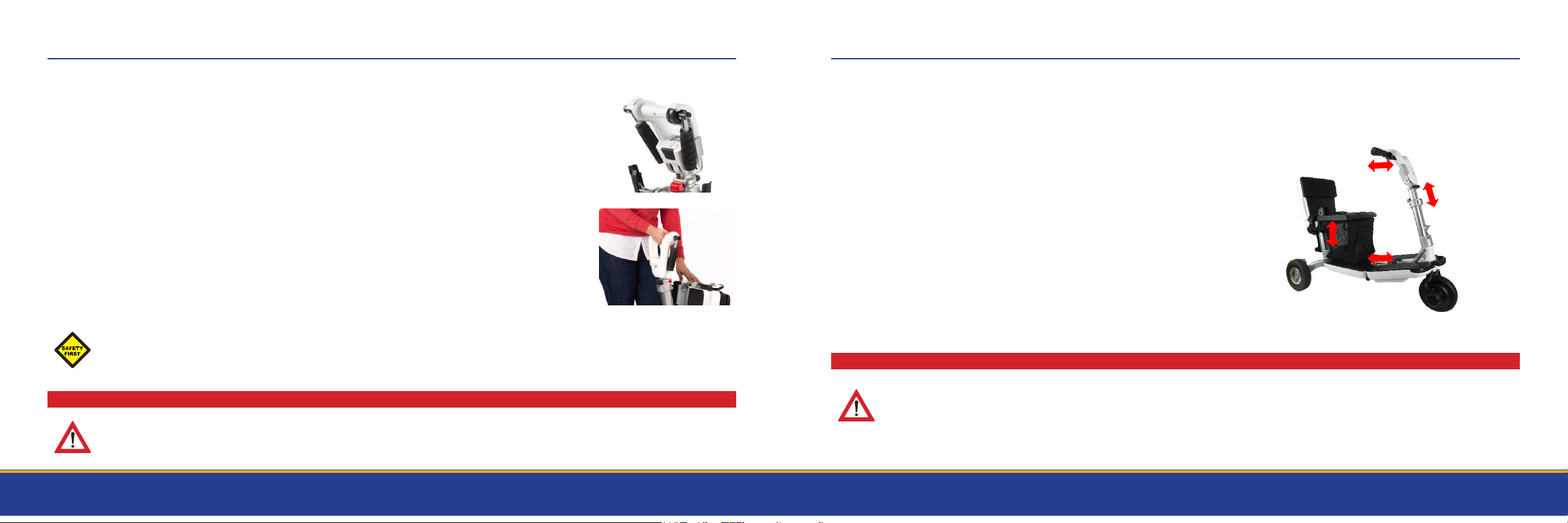
HOW TO MAKE HEIGHT ADJUSTMENT FOR COMFORT
1. You can adjust the Steering Console Height.
up or down. (see image 37)
You can adjust the Steering Console HandleAngle
closer to you or further away from you.
2. (see image 37)
3. You can adjust the Steering ColumnAngle closer
to you or further away from you.
(see image 37)
4. You can adjust the Seat Height up or down.
(see image 37)
There are 3 Rider Adjustments for Maximum User Comfort
WARNINGS
Adjusting angle and height components of the scooter can create pinch points. Be careful to follow the
instructions to prevent possible injury.
HOW TO CONNECT THE CHASSIS HALVES
Make sure the handlebar is secured at the upright position. (see image 35)
Place both chassis vertically.
Hold the front chassis from the handlebar and bring it towards the back chassis.
Bring the two parts together.
Use the hanging hooks located on the front chassis half to connect to the rear chassis.
Close the two separation levers until they click. (see image 36)
Step 1
Step 2
Step 3
Step 4
Step 5
Step 6
Follow These Steps in Sequential Order
image 35
image 36
SAFETY NOTE: In case the separation levers require too much force to operate, you should apply horizontal
pressure on the driving console handle towards the center of the scooter. This will release the pressure on
the separation levers and will allow them to close and lock in place more comfortably.
WARNINGS
Do not try to open the scooter for driving before the two levers are secured in the downward position.
24 25
image 37

HOW TO ADJUST FOR COMFORT
•Use the Steering Column lever to adjust the height of the Steering console to the
desired height up or down. (see image 38)
•Pull the steering column lever out to release the telescoping steering column.
(see image 38)
•Lift the Steering column to the desired height then return the steering column lever
into it’s locked position. (see image 39). This will lock the steering column at the
desired height.
•The steering column has preset “notches” to select the desired height of your
Steering Column.
Steering Console HeightAdjustment
image 38
image 39
HOW TO ADJUST FOR COMFORT
Adjusting the Steering ConsoleAngle
The Steering console is equipped with a variety of angle adjustments that can
accommodate your preferred driving angle.
26 27
image 40
image 41
1. To adjust the driving console, first be seated on the scooter.
2. Hold the driving console in one hand and release the adjusting lever using the
other hand. (see image 40)
3. Adjust the driving console angle so you can reach and hold it comfortably with a
clear view of the display.
4. Tighten the adjustment lever when you’re done. (see image 41)

•The seat is thin and stylish and is designed to provide comfort and safety with two
height adjustments and adjusted according to drivers height preferences.
•Pull the ring to make the seat / chair up and down for a comfortable height.
(see image 45)
HOW TO ADJUST FOR COMFORT
Seat HeightAdjustment
image 45
WARNINGS
Adjusting angle and height components of the scooter can create pinch points. Be careful to follow the
instructions to prevent possible injury.
HOW TO ADJUST FOR COMFORT
To adjust the angle you need a 4 mm alien wrench. The Scooter has to
be in the open position to adjust the Steering Column angle. (see image 42)
Once the scooter is opened, locate and release the two Alan hex-screws.
These are located on the side of the steering column. (see image 43)
Make sure you are holding the steering column upright. Once the Alan Hex Screws are
removed, move the steering column into the desired position and tighten the Alan hex-
screws. (see image 44)
Step 1
Step 2
Step 3
Steering ColumnAngle Adjustment
image 42
image 43
image 44
•The steering column angle can be adjusted in one of two positions according.
•The default position will be adequate for most users. However, larger users may want
the steering column further away from their body allowing for more space.
28 29

•The on/off button is located at the center of the driving CONSOLE below the display
panel. To turn the scooter on, press andhold the power button until the scooter dash
lightsup.(see image 49)
•The two buttons on the sides of the Power Button marked with “+” & “-” are the
speed buttons.
•Along with the number shown on the display panel the “+” and “-” buttons set the
maximum/minimum speed of the scooter.
•It is recommended that you only adjust the speeds while the scooter is not moving.
Click the “+” button to increase the speed and the “-” button to decrease the speed.
The driving console (the scooter dashboard) contains all the controls and display
features needed for operating your mobility scooter.
THE STEERING CONSOLE
WARNINGS
It is highly recommended you use the lowest speed setting when initially learning to drive. When operating in
crowded places and near obstacles, use extra care and reduce the maximum speed allowing you to control
your mobility scooter without presenting a risk to others or yourself.
image 49
30 31
THE STEERING CONSOLE
The Display Panel
•The battery level meter illuminates when the scooter power is turned on.
(see image 50)
•The battery meter indicates the approximate battery charge remaining.
•As with all Lithium Ion Batteries, the charge level indication is accurate only
when the scooter is being charged. All other indicators are approximate
and intended to give you a general idea of the battery life remaining.
WARNINGS
Your scooter will automatically shut down if the battery output falls below operation voltage.
image 50

THE STEERING CONSOLE THE STEERING CONSOLE
Throttle Control
•The throttle is used for driving and controlling the driving speed.
•Place your thumb on the throttle lever and press it down to accelerate. (see image 53)
•To decelerate, release pressure on the throttle to your desired comfort level.
•To bring the scooter to a complete stop remove your thumb from the throttle.
This will bring the scooter to a controlled stop.
Driving Direction
•The NEWTON Scooter can drive both forward and in reverse.
•The driving direction is shown on the display panel by an arrow pointing forward or
backward. (see image 51)
•To switch the driving direction press the directions button located near the left-hand grip as seen
in. (see image 52)
•Once the driving direction has changed the 3-Wheel Scooter will sound a single beep when
in forward-driving mode. A double beep will sound when in reverse-driving mode.
•When the Independence Series 3-Wheel Scooter is turned on it will always power on in the
forward driving mode.
image
51
32 33
image 52
image 53
•Press the horn button to sound the horn. Always used the horn when needed to pre-
vent accident or injury. (see image 54)
SAFETY FIRST
Always bring the mobility scooter to a full stop before changing the
driving direction (meaning changing from normal driving to
reserves)
Always alert those around you with the horn if you feel an unsafe
environment exists.
image 54

THE STEERING CONSOLE
USB Port
•Newton is equipped with a USB charging port. (see image 55)
Display dimming
•Pressing the “+” & “-” buttons simultaneously will toggle the dimming option of the Display
Beep Sounds
•Beeps caused by pressing buttons may be enabled or disabled.
•To enable, press the “+” and “horn” buttons simultaneously. To mute the beeps,
press the “-” and horn buttons simultaneously (see image 56)
•For safety reasons, the horn is always enabled.
image 55
image 56
THE STEERING CONSOLE
34 35
LED Light
•When your Newton scooter is in a driving mode, press the power on/off button to turn on the
LED light, and press and hold the power on/off button for a few seconds to turn it off. (see
image 57)
Laser Obstacle Avoidance
•To fold the handlebar grips pull the grip away from the Steering consul and rotate them down to
a folded position. (see image 58)
•The grips will automatically lock themselves into position.
image 57
image 58

Getting On the Scooter
Step 1 Verify that the scooter is turned off.
Verify that the scooter is open completely and in the driving position.All levers should be locked and
secured in place.
Carefully place one foot on the approximate center of the deck and seat yourself comfortably and securely
on the seat in an upright position.
HOW TO OPERATE
WARNINGS
Do not lean on the handlebar or Steering Column for support as you enter or exit the scooter. The handlebar
could unintentionally move and cause you to lose your balance which could result in personal injury.
Never step on or off the scooter using the seat or the seat backrest for support. The seat back may fold
unintentionally and may cause you to lose your balance which could result in personal injury.
Step 2
36 37
Step 3
HOW TO OPERATE
Verify that the power is turned off. (see image 59)
Carefully place one foot on the ground on the side of the scooter. (see image 60)
Step away from the scooter.
Step 1
Step 2
Step 3
Getting Off the Scooter
image 60image 59
Table of contents
Other iMoving Scooter manuals


