The Calibration device BM561 is used to calibrate the Benkelman beam,to determine the real ratio betwen the
longer arm and the shorter arm on the swinging beam.
This appliance is for the exclusive use for which it has been designed.
Any other use is considered improper and therefore negligent.
Machine use is allowed only in places free from danger of explosion or fire.
During operation check for conditions of danger.
immediately stop the machine should it be working irregularly, and consult the authorised dealer’s Sales Service
department.
It is the Client’s responsibility to verify at the time of installation and use that no conditions of use arise which are
different to those indicated.
Refer to the Manufacturer in case of doubt.
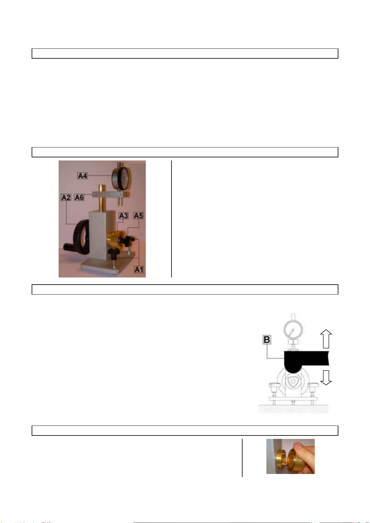
GENERAL DESCRIPTION OF THE DEVICE
This calibration device is composed of:
•A1 Aligning knobs.These knobs allow to align the
instrument to obtain an horizontal spirit level.
•A2 Operating knob. By spinning this knob it is possible
to operate the eccentric wheelA3 .
•A3 Eccentric wheel.
•A4 Centesimal gauge.Allows to read the real oscillation
of the beam arm.
•A5 Knob.
Allows to lock or remove the eccentric wheelA3
•A6 Gauge support. Holds the gauge A4
PRACTICAL EXAMPLE
Below is a typical procedure to allow the user to carry out a calibration
Instructions to be followed:
1. Using a spirit level, align the instrument using the knobsA1
2. Place the emispherical front end of the Benkelman beam (B) on the
eccentric wheel A3; lower the gauge holder to let tip of the gauge touch the
upper part of the beam’s emispherical end.
3. Turn the knobA2to cause a vertical movement of the oscillating beam.
4. Read and record on the gauge A4 the displacement of the beam’s end;
contemporarily record the displacement shown on the gauge of the
benkelman beam.
5. From the ratio between the two values you will be able to obtain the real
measuring ratio of the beam.
HOW TO ADJUST THE OSCILLATION HEIGHT OF THE ECCENTRIC WHEEL
It is possible to adjust the oscillation of the eccentric wheelA3 by unscrewing the
knob A5 and changing its wheel position on the centering plots on which it is
fixed (see picture on the right).