SINOCHIP DF-T4 User manual

Agriculture Drone User manual
Shenzhen Top-peak Electronics Co., Ltd.
Agriculture Drone User manual
Agriculture Drone User manual
FCC ID: 2AN97-DF-T4
DF-T4
SINOCHIP
Agriculture Drone User manual Agriculture Drone User manual
Users are advised to read this manual carefully before using this product. By using
this product, user are considered to acknowledge and accept all contents of this
statement. This product is not suitable for users under age 18.
Thank you for purchasing from SINOCHIP. This product is a high efficiency
agricultural spraying drone. Please strictly follow operation methods of this manual. It is
highly recommended NOT to turn on the main power while installing propellers to avoid
accidents. Please use it only when you are away from people, dangerous and fragile
goods. SINOCHIP will not bear the liability if any personal injur y and property damage
caused directly or indirectly by the following reasons:
(1).Start to use the product without carefully reading this manual in advance.
(2).Operate the product in drinking, drug abusing, fatigue, bad physical or mental
situation.
(3).Hurt people on purpose with the product.
(4).Unauthorised user modification on the product and cause damage.
(5).Damages caused by operation errors or subjective judgement mistakes.
(6).Damage caused by abnormal flight because of natural device abrasion, circuit
aging, etc.
(7).Operate the product in situations that knowing device is in no-fit and abnormal
status.
(8).Operate the product in extreme bad weather like typhoons, hail, snow, etc.
(9).Operate the product in area with interference of magnetic, radio, or no-fly zone.
(10).Operate the product in low visibility or when sight is blocked.
(11).Other losses that are not within the scope of SINOCHIP liabilities.
Intellectual property
The intellectual property of this product manual belongs to Shenzhen Top-peak
Electronics Co., Ltd. Without written permission, no organization or individual may
copy, reproduce or publish in any form. In case may need take this manual for reference,
please indicate the source, and any changes, deletions and references shall not be
contrary to original contents.
1. Disclaimer
SINOCHIP T series drones are considered high quality and perfect Performance
aircraft in the market. Product functions are listed as below:
• Semi-automatic Operation Mode
• A→B Point Operation Mode
• Support Radar Wave Altitude Sensor
• Dose Detection Function
• GPS Record Spraying Breakpoint
• Low Voltage Protection
• Auto-return in Out-Of-Control Situation
2.Product Introduction
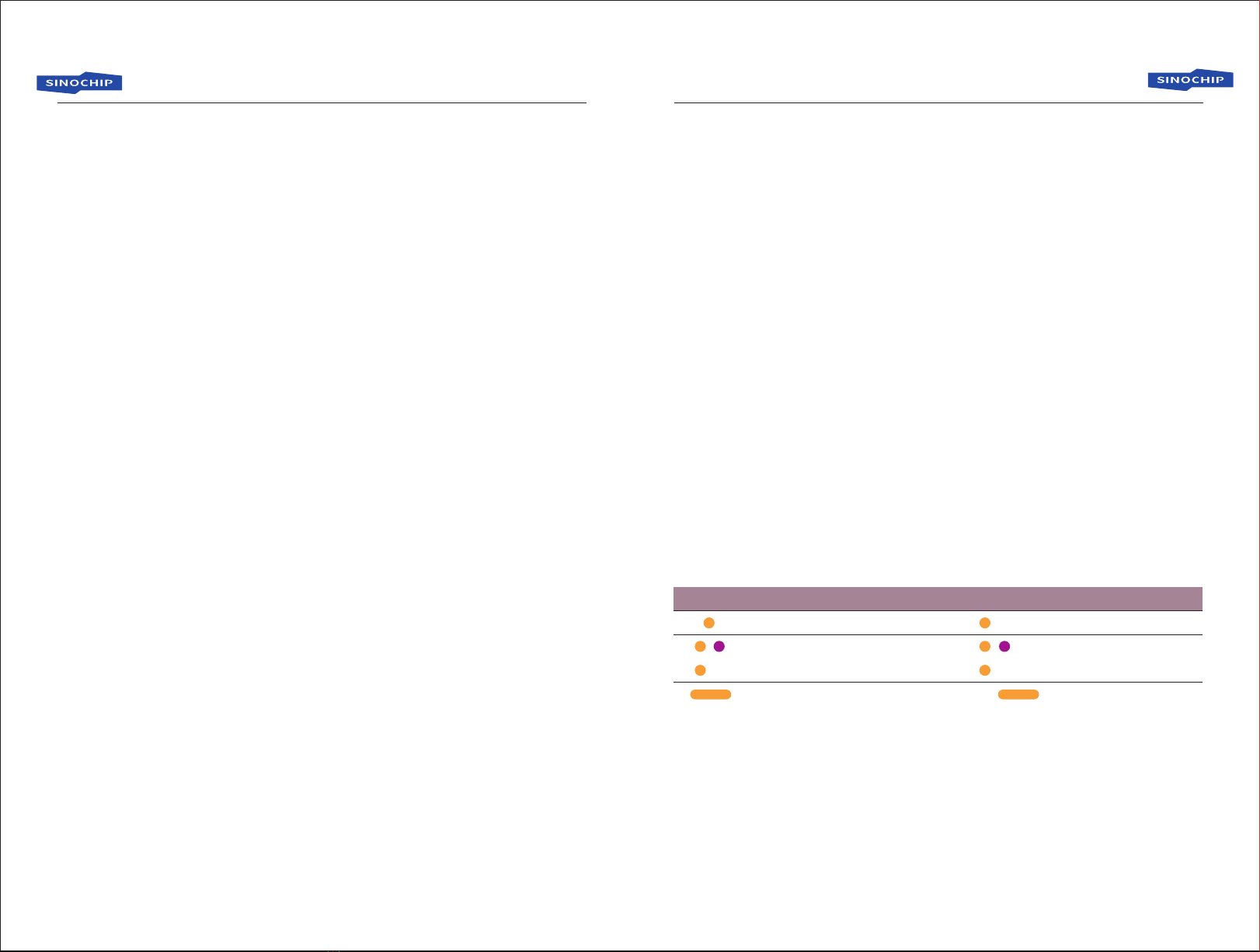
3.LED Symbol Description
Symbol description
means LED light flash in color for “N”times.
means LED light flash in color for “N”times.
means LED light flash in color continuously.
means LED light keep on in color for“N”seconds.
(N)
{ }(N )
(∞)
(N)
01 02
Agriculture Drone User manual Agriculture Drone User manual
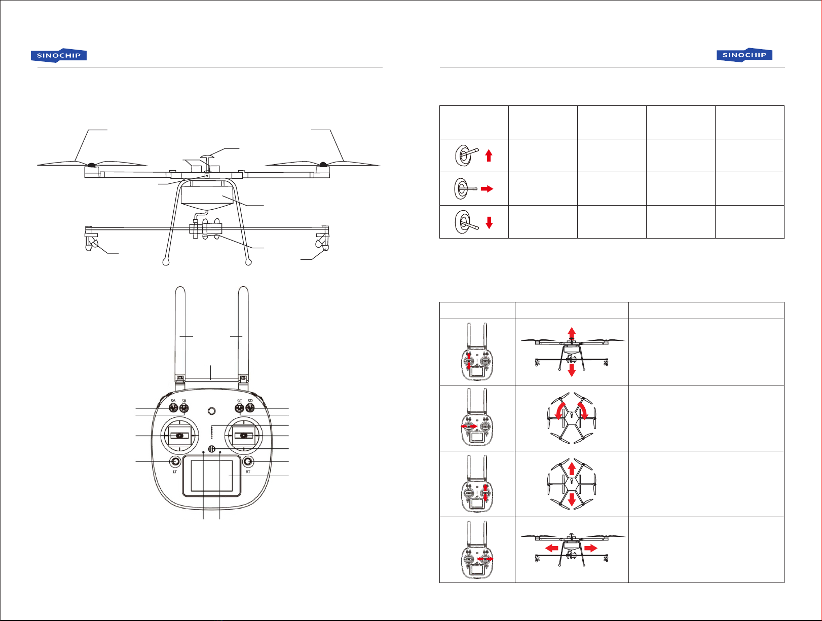
4. Introduction of Drone and Remote Control
Propeller
GPS
Battery
LED Light
Water Tank
Propeller
Nozzle Nozzle
Pump
Antenna
Handle
SA
SB
SD
SC
Throttle Joystick Direction Joystick
Speaker
Digital Trimming Digital Trimming
Status LED Charging LED
Hanging Hook
Touch Screen
!The remote control is default American handle mode. Above marked switches are
needed in the flight, others without remark are not necessar y during flight.
5. Remote Control Switch Functions
GPS
SD SC SB SA
6. Introduction Of Joysticks
Gesture Mode
Spray Mode
GPS Mode
Standby
Spray on
Return
Standby
Standby
A→B Mode
Record Point A
Standby
Record Point B
Remote control Drone Description
1. Push throttle joystick up, drone ascends.
2. Pull throttle joystick down, drone descends.
3. When drone comes to required altitude, do not move
the joystick,the drone will hover at the current height.
Push throttle Joystick slowly to avoid aircraft ascend or
descend too quick
1. Pull throttle joystick left, drone rolls left.
2. Pull throttle joystick right, drone rolls right.
1. Push direction joystick up, drone fly forward.
2. Pull direction joystick down, drone fly backward.
1. Pull direction joystick left, drone fly left side.
2. Pull direction joystick right, drone fly right side.
03 04
Agriculture Drone User manual Agriculture Drone User manual
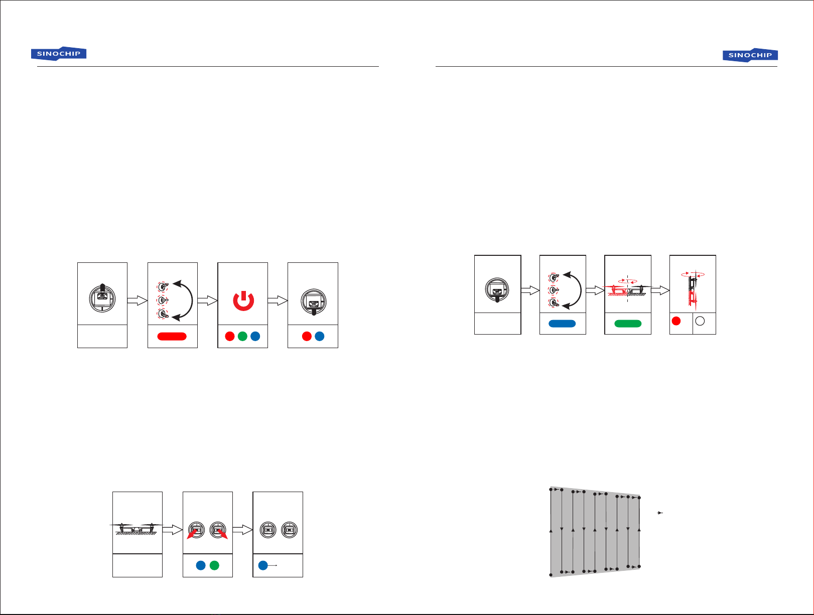
(1). Electric Speed Control(ESC) Calibration
The drone has been calibrated when it leaves factory, but if the motor speed is
obviously inconsistent during the later flight, please calibrate the drone again as follows:
Step1:Power on the drone and push throttle joystick to top, then LED indicates the
current GPS status and flight mode
Step2:Toggle SD quickly for 6-10 times from top to bottom until LED light up in RED.
Step3:Hold the throttle joystick, plug drone power off and then power on, the LED
will flash once in turn of RED, GREEN and BLUE.
Step4:After power on for about 0.5 seconds, the drone will “DiDi” sound twice.
pleasepull the throttle joystick to bottom in 2 seconds,and drone will
“DiDi”sound twice again. LED will flash in RED and Blue normal status.
Operation diagram:
7. Drone Calibration Instruction
throttle
joystick to top
toggle SD
for 6-10 time
hold Joystick,
cut off and
power on
joystick to
bottom
after "Di" for
twice
LED Indicates
GPS status and
flight mode
(2).Horizon Level Calibration
The drone has been calibrated when it leaves factory, if it tilts seriously towards
certain direction during later flight, please calibrate the drone again as follows:
Step1:Put the drone on horizontal ground, make sure it doesn't shake.
Step2:Lock the drone by holding the joysticks like second diagram for 10 seconds
until LED flash alternately in BLUE and GREEN.
Step3:Release the joysticks, LED will flash in BLUE about 10 seconds later, and
then LED will flash normally after 15 seconds.
Operation diagram:
Horizontally land
LED Indicates
GPS status and
flight mode
Lock the drone Release the
joysticks
Flash
normally
(3).Compass Calibration
Compass calibration is required when the aircraft takes off first time or changes
location (50KM from the last flight position). The calibration method is as follows:
Step1:pull throttle joystick to bottom.
Step2:Toggle SD quickly for 6-10 times from top to bottom until LED light up in BLUE.
Step3:Place the drone head facing forward horizontally, slowly turn the drone
clockwise at least one round until the LED green light is on
Step4:Place the drone head down, fuselage vertical, and then slowly turn
clockwise at least one round until the LED light up in WHITE for 4 seconds.
If the LED light up in RED for 4 seconds, indicating calibration failure, repeat steps
2-4 until succeed.
Operation diagram:
(4) (4)
LED Indicates
GPS status and
flight mode
throttle
joystick
bottom
toggle SD
for 6-10 times turn clockwise
ok Fail
(1).Gesture mode
In gesture mode, without too much data to calculate, the drone respond fast but cannot
Hover at fixed-point, this mode is suitable for skilled pilot.
(2).GPS mode
With good GPS signal, the drone can hover at fixed-point in GPS mode.
(3).Spray mode
Spray mode is based on GPS mode, only with good gps signal, user can enter this mode.
operate method as follows:
8. Flight Mode Introduction
line change point
start point
Operating Interval
05 06

Agriculture Drone User manual Agriculture Drone User manual
Step1:Fly the drone to the start point, switch SD to Spray Mode and SC to Spray On
then push or pull the direction joystick over 15% from the middle position, the
drone will spray in uniform speed and fixed height.
Step2:When the drone fly to a line change point, release direction joystick back to
middle position, now the drone will hover. pull direction joystick left or right and
then middle, it will fly to the start point of next line.
Step3:Repeat step 1-2 to finish the spray work .
During spraying, the height can be adjusted accordingly, the drone will fly at fixed
height when throttle joystick stay at the middle position.
Spray flow rate associated with the flight speed of the drone, the greater the speed
the greater the flow; it will stop spraying when speed is less than 0.5 m/s.
(4). A-B Point Mode
A-B point mode is a fast automatic route planning mode, users need to confirm the GPS
signal is good. methods are as follows:
A
B
Operating inter val
Route L
Step1:Fly the drone to start point A, SA switches from STANDBY to “RECORD POINT
A”position,then the drone will record point A gps coordinate, LED will flash 10
times in RED (10)
Step2:Fly the drone to Point B position, SA switches to “RECORD POINT B”position,
then the drone will record point B gps coordinate, LED will flash 10 times in
GREEN (10)
Step3:Switch SB to A-B MODE, LED flash 8 times in BLUE (8), pull direction joystick
left or right and then middle, it will fly to the start point of next line and then fly in
route L and spray in uniform speed and fixed height.
Step4:Quit A-B MODE when finish spraying, the drone will hover.
• Only in spray mode or GPS mode can record A and B point.
• A-B mode is not available when the drone is on ground.
• During operation, the LED flashes 3 times in RED (3) when flying to point A, and
then flashes 3 times in GREEN (3) when flying to point B.
• Erase A and B point: 1) Exit A-B mode, re-record the A and B point; 2) Toggle SA up and
down 8times and LED will flash 10 times in YELLOW (10); 3) A and B point will be
erased when erase the pesticide break point(refer to next page); 4)If pesticide
breaking point has not been recorded , A and B point will be erased automatically when
the drone land and auto locked.
The drone has dose detection function, when the dose is insufficient, the drone will
record breaking point, and will automatically fly to the breaking point to restart spraying
after reloading pesticide. Dose sensor switch interface is as the following figure, you can
disconnect it and cancel the dose detection function.
9. Restart At Pesticide Breaking Point
Two interfaces: Green is for battery power
of the pump, RED is for dose detection
Step1:When low dose is detected, the aircraft will decelerate, automatically rise 1.5
meters and hover (Gesture / GPS mode will not rise), record the current
position, LED flash 4 times in light blue (4), in the process of rising , you can
switch SD to stop rising, the drone still records pesticide breaking point.
Step2:When finish rising, the drone will hover, you can manually operate the drone to
return or press the auto return switch(if HOME position recorded).
Step3:After reloading, the drone will automatically rise to the 2.5meter height and fly
back to break point, and then drop to the operating height and restart spraying
(you can pull throttle joystick to stop dropping).
• If the drone record the breaking point, pull the throttle up to 70% and then back to
middle when it is rising, and then it will automatically fly back to the breaking point and
restart spraying.
• Spray mode, A-B mode, gesture mode and GPS mode all allow record breaking POINT,
but automatic flight back to the point is NOT available in gesture mode.
• Toggle SD 4 times can erase the current breaking point. Also it will clear automatically
After drone landing and locking for 15 minutes.
07 08
Agriculture Drone User manual Agriculture Drone User manual
Only when the GPS signal is good and return landing position has been record
before flight starts (LED will flash 10 times in BLUE if recorded (10) ), can the drone
receive return command, method as follows:
Step1:Switch SC to RETURN position, the drone will automatically rise 1.5 meters and
hover, (will not rise in gesture mode or GPS mode), and record the breaking point.
Step2:Toggle SC once and back to RETURN position, the drone will rise up 2 meters
and then return.
Step3:Restart the drone (refer to method of restart at pesticide breaking point). the drone
will automatically rise to the 2.5meter height and fly back to break point, and then
drop to the operating height. (user can pull throttle joystick to stop dropping)
10. Return Command
If remote control signal lost, LED will keep flash in YELLOW and BLUE (∞ ),
after hovering for 5 seconds, the drone will return to the take-off position, land and lock .
if the signal recovered during return flight, it will stop returning and switch back to RC
current SD mode.
11 Out of Control Protection
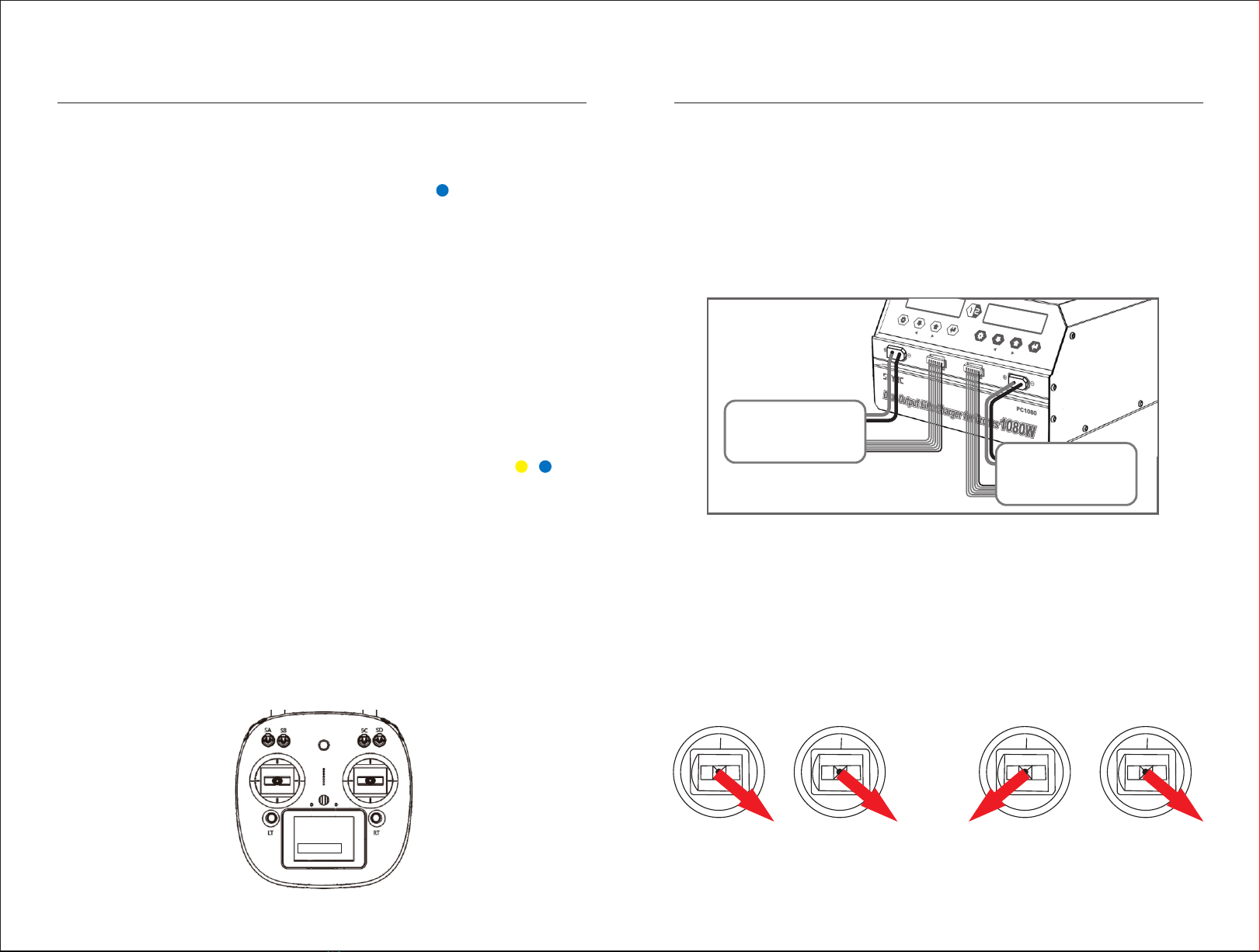
During flight, battery voltage PWR will be displayed real-time on remote control
screen (display position as below configure). When drone battery voltage is lower than
43.5V, remote control will give voice and vibration alarm. The drone can last about 2
minutes at this time, please land the drone in time and replace batteries.
12. Low Voltage Alarm
PWR:43.5V
6S Lipo Battery
设置/停止确认/开始
选项
设置/停止 选项 确认/开始
Battery Charging: User shall charge battery when voltage is low. (input power AC100-240V)
Connect battery like below configure, connect power cable, press “start” 2 seconds
to charge. Once charging finished, it will show “charging finished” on screen, full voltage
should be around 25.2V.
If the batteries are not used for more than 10 days, user shall use “charge for
storage” mode to keep battery in a storage voltage.
13.Battery Charge
6S Lipo Battery
Unlock Lock
Only one way available for locking and unlocking the drone. show as follows: pull
the throttle joystick for at least 3 seconds after the drone land, it will lock automatically.
and rotors will start one by one after unlocking.
14. Lock and Unlock the Drone
09 10
Agriculture Drone User manual Agriculture Drone User manual
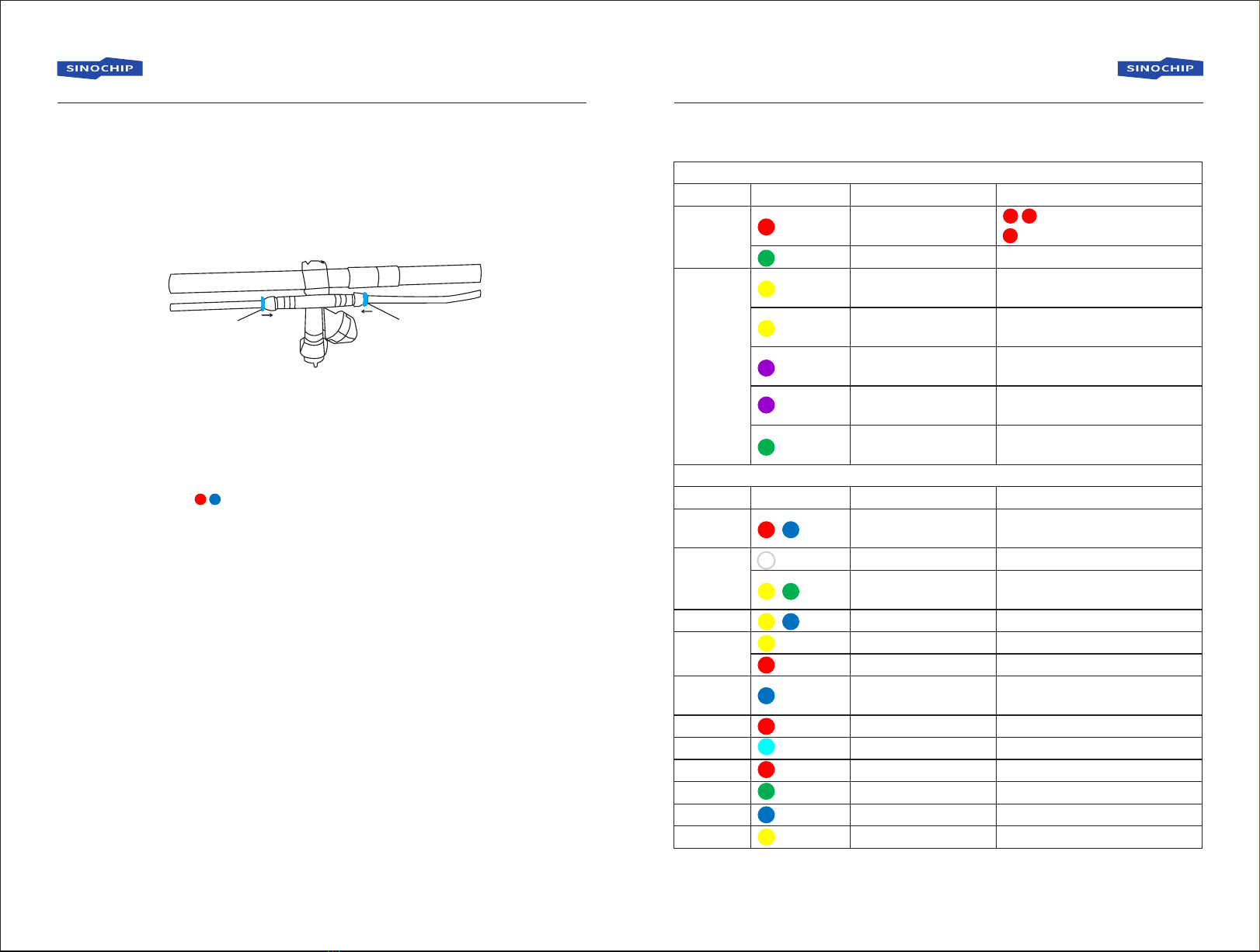
(1). Propellers: install the propeller correctly according to the marks CCW/CW, put on
the gasket and then tighten with a screw.
(2). Water pipe connection: tighten the spray rod, clamping to the drone, connect the
pipes and then connect the pipes to the pump. as follows:
15. Others
press the blue piece when
connect/disconnect the pipe
press the blue piece when
connect/disconnect the pipe
Step1:turn on the remote control and then power on the drone.
Step2:after LED flash( )(10),make a compass calibration (please refer to page 6).
Step3:after the calibration is complete, install the propellers correctly.
Step4:wait for GPS signal search, LED will flash singly turn from RED to GREEN if succeed.
Step5:check if the LED flash correctly according to the correct flight mode.
Step6:step away from the drone for at least 5 meters, unlock the drone and start flying.
16. First Flight
• Please disconnect the dose detection cable or clear the pesticide breaking point
before the compass calibration, in case it may record a wrong breaking point because of
unloading.
• Please operate the joysticks slowly.
• Please keep SA, SB, SC in STANDBY mode before unlocking the drone.
(2) 1)
(2)
(2)
}(10
(∞)
}(∞
}(∞
( ∞ )
( ∞ )
(10)
( 5 )
( 4 )
(10)
(10)
(8)
(
10)
(
(
Normal flight indications: first flash GPS status lights, and then flash flight mode lights
Content
GPS status
flight mode
Special status indications: these flashes take precedence over the normal flight indications.
Content
Initialization
status
Sensor
status
RC status
Voltage
status
Return
position
record
location status
breaking point tip
A point record
B point record
A-B route mode
clear AB point
Flash
Flash
(
Hardware initialization,
gyro bias has been
corrected
IMU or barometer data
is abnormal
compass data is abnormal
remote control lose the signal
low voltage alarm level 1
low voltage alarm level 2
record the return position
arrive the specified location
breaking point exist
A point recorded
B point recorded
A-B route available
AB point cleared
Meaning
GPS function unavailable
GPS function available
Auto flight mode
Meaning
Remark
(2)GPS signal below level-7
(1)GPS signal above level-7but not good
it flashes in any auto flight mode
such as auto return and auto spraying.
Remark
Check if magnetic interference
and recalibrate the compass
Reconnect the power to see if it
keep in stillness
It records once during the first GPS
positioning as well as ever y time the
motor is started
17. LED Indicator Introduction
11 12
}
}
}
(
Gesture mode,no
pan & tilt command
Gesture mode with
pan & tilt command
GPS mode, no
pan & tilt command
GPS mode with
pan & tilt command

Caution:
ThisdevicecomplieswithPart15oftheFCCrulesandIndustryCanadalicense‐exemptRSS
standard(s).Operationissubjecttothefollowingtwoconditions:(1)thisdevicemaynotcause
harmfulinterference,and(2)thisdevicemustacceptanyinterferencereceived,including
interferencethatmaycauseundesiredoperation.
ThemanufacturerisnotresponsibleforanyradioorTVinterferencecausedbyunauthorized
modificationsorchangetothisequipment.Suchmodificationsorchangecouldvoidtheuser’s
authoritytooperatetheequipment.
Thisradiotransmitter(identifythedevicebycertificationnumberormodelnumberifCategoryII)
hasbeenapprovedbyIndustryCanadatooperatewiththeantennatypeslistedbelowwiththe
maximumpermissiblegainindicated.Antennatypesnotincludedinthislist,havingagaingreater
thanthemaximumgainindicatedforthattype,arestrictlyprohibitedforusewiththisdevice.
ThisequipmenthasbeentestedandfoundtocomplywiththelimitsforaClassBdigitaldevice,
pursuanttopart15oftheFCCRules.Theselimitsaredesignedtoprovidereasonableprotection
againstharmfulinterferenceinaresidentialinstallation.Thisequipmentgenerates,usesandcan
radiateradiofrequencyenergyand,ifnotinstalledandusedinaccordancewiththeinstructions,
maycauseharmfulinterferencetoradiocommunications.However,thereisnoguaranteethat
interferencewillnotoccurinaparticularinstallation.Ifthisequipmentdoescauseharmful
interferencetoradioortelevisionreception,whichcanbedeterminedbyturningtheequipment
offandon,theuserisencouragedtotrytocorrecttheinterferencebyoneormoreofthe
followingmeasures:
‐‐Reorientorrelocatethereceivingantenna.
‐‐Increasetheseparationbetweentheequipmentandreceiver.
‐‐Connecttheequipmentintoanoutletonacircuitdifferentfromthattowhichthereceiveris
connected.
‐‐Consultthedealeroranexperiencedradio/TVtechnicianforhelp.
ThedevicehasbeenevaluatedtomeetgeneralRFexposurerequirement.
TomaintaincompliancewithFCC’sRFexposureguidelines,thisequipmentshouldbe
installedandoperatedwithaminimumdistanceof20cmbetweentheradiatorandyour
body.
Table of contents


