impulce 2 IT8001B User manual
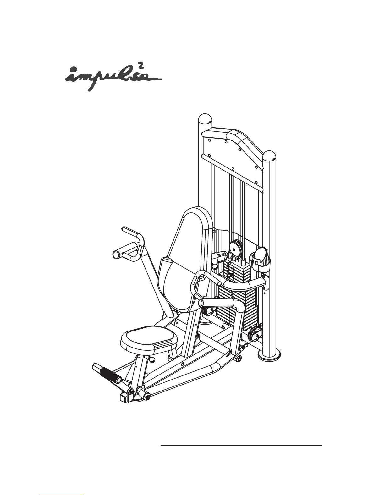
IT8001B Chest Press
Assembly Instructions

Table of contents
Important Safety Instructions--------------------------------- 1
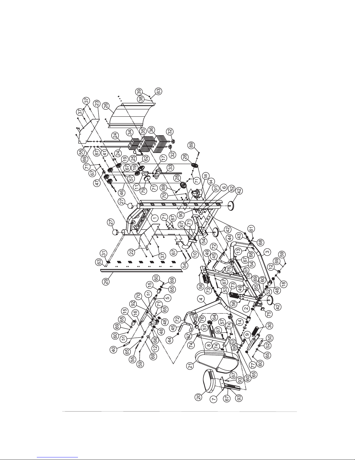
Exploded View Diagram------------------------------------------ 2
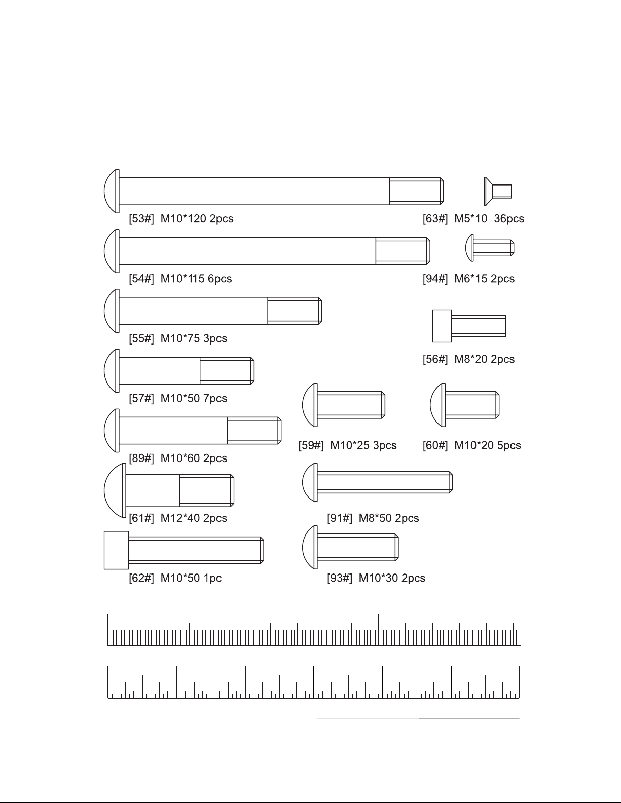
Hardware List--------------------------------------------------
Parts List-----------------------------------------------------
Assembly instructions------------------------------------------
------ 3
---------- 4
-- 5

Important Safety Instructions
Before beginning any fitness program, you should obtain a complete
physical examination from your physician. When using exercise equip-
ment, basic precautions should always be taken, including the following:
* Read all instructions before using the .
arewrittentoensureyoursafetyandtoprotect
* Do not allow children on or near the equipment.
* Use the equipment only for its intended purpose as described in this
guide. Do not use accessory attachments that are not recommended
by the manufacturer: such attachments might cause injuries.
* Wear proper exercise clothing and shoes for your workout---no loose
clothing.
* Be careful when getting on or off the equipment.
* Do not overexert yourself or work to exhaustion.
* If you feel any pain or abnormal symptoms, stop your workout imme-
diately and consult your physician.
* Never operate the unit when it has been dropped or damaged.
* Never drop or insert anything into any opening in the equipment.
* Always check the unit and its cables before each use. Make sure that
all fasteners and cables are secure and in good working condition.
* Frayed or worn cables can be dangerous and may cause injury.
Periodically check these cables for any indication of wear.
* Keep hands, limbs, loose clothing and long hair well out of the way of
moving parts.
* Do not attempt to lift more weight than you can control safely.
* Do not use the equipment outdoors.
* Read each step in the assembly instructions and follow the steps in
sequence. Do not skip ahead. If you skip ahead, you may learn later
that you have to disassemble compontents and that you may have
damaged the equipment.
* Assemble and operate the equipment on a solid, level surface. Locate
the unit a few feet from walls or furniture to provide easy access.
The is designed for your enjoyment. By
precautions and using common sense, you will have
pleasurable hours of healthfull exercise with the
Chest Press These instructions
the unit.
Chest Press following these
many safe and
equipment.
Personal Safety During Assembly
1

2
IT8001B CHEST PRESS
Exploded View Diagram

3
Hardware List
0 100
10 20 30 40 50 60 70 80 90 110 120 130 140 150
Inches
0123456
/
12
/
14 /
34 /
34 /
34 /
34 /
34 /
34
/
14 /
14 /
14 /
14 /
14
/
12 /
12 /
12 /
12 /
12
Millimeters

Hardware List
0 100
10 20 30 40 50 60 70 80 90 110 120 130 140 150
Inches
0123456
/
12
/
14 /
34 /
34 /
34 /
34 /
34 /
34
/
14 /
14 /
14 /
14 /
14
/
12 /
12 /
12 /
12 /
12
Millimeters
4

Parts List
Item No. Description QTY Item No. Description QTY
1
2
3
4
5
6
7
8
9
10
11
12
13
14
15
16
17
18
19
20
21
22
23
24
25
26
27
28
29
30
31
32
33
34
35
36
37
38
39
40
41
42
43
44
45
46
47
1
1
1
1
1
2
1
1
1
1
1
3
2
1
2
1
1
4
5
1
1
1
1
2
1
1
2
2
2
1
16
2
1
5
8
6
14
4
4
1
2
3
2
2
2
1
2
48
49
50
51
52
53
54
55
56
57
58
59
60
61
62
63
64
65
66
67
68
69
70
71
72
73
74
75
76
77
78
79
80
81
82
83
84
85
86
87
88
89
90
91
92
93
94
6
2
1
2
8
2
6
3
2
7
1
3
5
2
1
36
1
7
2
40
4
9
3
16
2
2
3
1
2
1
2
2
1
1
1
1
1
1
1
1
1
2
2
2
1
2
2
Main Upright
Main Support
Left Press Arm
Right Press Arm
Sway Bracket
Swing Pulley Bracket
Seat Pad Support
Back Pad Support
Assistant Frame
Support Bracket
Straight Pulley Bracket
Big Washer 55×13
Nylon Locknut M12
Joint Rod Assembly
Wheel 50× 25.5×75
Shaft
Jam Nut 1/2"-12
Adj Ring 30×2×3
3.5"Pulley
Seat Pad 460×280×70
Back Pad380×280×820×120
Front Decal Plate
Rear Decal Plate
Guide Rad 19×1385
Weight Pin
Weight Shroud
"D"End Cap
V Type Pulley
Side Cover
Foot Sleeve 48× 56×164
Plastic Block
Weight Rubber Bumper
Top Plate
10LBS Weight
15LBS Weight
20LBS Weight
Button
Plastic Washer
Bolt Cover
Gas Spring
Rubber Cap 25.5×20
Adj.Foot Plate
Gimbal
End Cap 25
Handle Grip 24× 32×460
Cable
Cable Retainer
Φ
ΦΦ
Φ
Φ
ΦΦ
Φ
Φ
ΦΦ
Bearing
Pop Pin
Small Shaft
Bronze Bushing
Bronze Bushing
Allen Bolt M10×120
Allen Bolt M10×115
Allen Bolt M10×75
Socket Screw M8×20
Allen Bolt M10×50
Plastic Cap
Allen Bolt M10×25
Allen Bolt M10×20
Allen Bolt M12×40
Socket Cap Screw M10×50
Chamfer Bolt M5×10
End Cap
Washer 38× 11×2
Clip 25
Washer 11× 20×2
Washer 13× 24×1.5
Spring Washer 10
Nylon Locknut M8
Nylon Locknut M10
Split Pin 4×25
Sleeve RT50×100
Plug
ΦΦ
Φ
ΦΦ
ΦΦ
Φ
Φ
Φ
Φ
Φ
ΦΦ
ΦΦ
□25×50×2
Plug 50
Plug 60
Plug 48
Adjustable Stopper
Small Pulley Cover 114×24
DecalWeightNumber
DecalWarning
Decal Maintenance Routine
Decal Pinch Point
Decal Tightening
Decal Note
Key S=6
Key S=8
Grease
Allen Bolt M10×60
Limited Ring 26× 38×16
Allen Bolt M8×50
Washer 9× 16×1.6
Allen Bolt M10×30
Button Head Cap Screw M6×15
□
5

Assembly instructions
Assembly of the takes professional installers about
2 hours. If this is the first time you have assembled this type of
equipment, plan to spend more time. It is strongly recom men
ded to assemble the equipment by professional installers.
You may find it quicker, safer, easier to assemble this equipment
with the help of a friend, as some of components may be large,
heavy or awkward to handle alone. It is important that you asse-
mble your product in a clean, clear, uncluttered area. This will
enable you to move around the product while you are fitting com-
onents and reduce the possibility of injury during assembly.
As with any assembled part, proper alignment and adjustment
is critical. While tightening the fasteners, be sure to leave room
for adjustments. Do not fully tighten the fasteners until instructed
to do so. Be careful to assemble the components in the sequence
presented in this guide.
Chest Press
-
p
Note
6

Step1 Install The Adj.Foot Plates
Align the Adj.Foot Plates (#42) to the Main Upright(#1)
and the Main Support(#2) then secure them by hands.
7

Step2 Assemble The Frame
1)Attach the Main Support (#2) to the Main Upright (#1)
using:
2)Attach the Support Bracket (#10) to the Main Upright
(#1) using:
3)Attach the Support Bracket (#10) to the Main Supoport
(#2) using:
Two Allen Bolts (#54) M10×115
Four Washers (#67) 11× 20×2
Two Nylon Locknuts (#71) M10
Four Allen Bolts (#54) M10×115
Eight Washers (#67) 11× 20×2
Four Nylon Locknuts (#71) M10
Two Allen Bolts (#53) M10×120
Four Washers (#67) 11× 20×2
Two Nylon Locknuts (#71) M10
ΦΦ
ΦΦ
ΦΦ
8

Step3 Assembly The Assistant
Force Parts
1)Attach Sway Bracket (#5) to the Main Support (#2)
Using:
2)Attach Assistant Frame (#9) to the Main Support (#2)
Using:
3)Attach Joint Rod Assembly (#14) to Assistant Frame
(#9) Using:
4)Attach Joint Rod Assembly (#14) to Sway Bracket (#5)
Using:
5)Attach Gas Spring(#40) to the Main Support (#2)and
the Sway Bracket(#5) Using:
Two Spring Washers 10(#6 )
9× 16×1.6(#92)
One Nylon Locknut M8(#70)
Φ
Φ
Φ
ΦΦ
Φ
Φ
ΦΦ
ΦΦ
ΦΦ
One Clip 25 (#66)
One Big Washer 55×13(#12)
OneSpringWasher 10(#69)
One Allen Bolt M10×25(#59)
One Small Shaft (#50)
Two Washers 38× 11×2(#65)
Two Allen Bolts M10×20(#60)
One Clip 25 (#66)
Two Washers 38× 11×2(#65)
Two Allen Bolts M10×20(#60)
One Shaft (#16)
Tow Washers 38× 11×2(#65)
One Allen Bolt M10×75(#55)
One Nylon Locknut M10 (#71)
One Washer
9
Note
Need to adjust the two Adjustable Stopper (#78)
height. Assure that the Gas Spring is not limited
location.
9

Step 3
10

1)Attach The Left Press Arm (#3) to Main Support (#2)
Using:
2) Attach The Right Press Arm (#4) to Main Support (#2)
Using:
Φ
Φ
Φ
Φ
Φ
Φ
Two Adj Rings 30×2×3(#18)
One Big Washer 55×13(#12)
OneSpringWasher 10(#69)
One Allen Bolt M10×25(#59)
Two Adj Rings 30×2×3(#18)
One Big Washer 55×13(#12)
OnespringWasher 10(#69)
One Allen Bolt M10×25(#59)
Step4 Assemblies The Left Press Arm (#3)and Right
Press Arm (#4) to Main Support (#2)
11

Step5 Assemble The Weight Plate
1)Insert the two Guide Rod (#24) into the Main Upright
(#1).
2)Slide the Weight Rubber Bumper(#32) down onto each
Guide Rod(#24).
3)Carefully begin sliding the Weight Plates one by one
in sequence: #33, #34, #35,#36
4)Align both top ends of the Guide Rods(#24) to the Main
Upright (#1) and secure them. Using:
ΦΦ
Φ
Φ
Two Allen Bolts M10×75(#55)
Two Washers 11× 20×2(#67)
Two Spring Washers 10 (#69)
Two Rubber Caps 25.5×22(#41)
12

Step6 Route The Cable
1)Put the Clip Tied on the Weight Pin Leash onto the Top
Plate (#33) as shown below, next connects Straight
Pulley Bracket (#11) to the Top Plate (#33) Using:
2)Joint Cable one end to The Left Press Arm (#3) U bra-
cket Using:
3)Route the Cable (#46) over V Type Pulley (#28) Using:
4)Route the Cable (#46) Up the two 3.5" Pulleys (#19)
Using:
5) Route the Cable (#46) Down the 3.5"Pulleys (#19) on
Support Bracket (#11) Using:
6)Route the Cable (#46) Up the two 3.5" Pulleys (#19)
Using:
7)Route the Cable (#46) Down V Type Pulley (#28) Using:
8) Joint Cable another end to The Left Press Arm (#3) U
bracket Using:
9)Adjust the tension of the Cable (#46) using the Jam
Nut (#17)
10)Make sure that the cables are in the groove of all the
pulleys then fully tighten all bolts and nuts
11) Select an appropriate weight by the Weight Pin
One Jam Nut 1/2"-12(#17)
One Nylon Locknut M12 (#13)
One Allen Bolt M12×40(#61)
Two Washers 13× 24×1.5(#68)
One Allen Bolt M10×60(#89)
Two Washers 11× 20×2(#67)
One Nylon Locknut M10 (#71)
One Cable Retainer (#47) (Note direction)
Two Allen Bolts M10×50(#57)
Four Washers 11× 20×2(#67)
Two Nylon Locknuts M10 (#71)
One Socket Cap Screw M10×50(#62)
One Nylon Locknut M10 (#71)
Two Small Pulley Covers 114×22 (#79)
One Cable Retainer (#47) (Note direction)
Two Allen Bolts M10×50(#57)
Four Washers 11× 20×2(#67)
Two Nylon Locknuts M10 (#71)
One Allen Bolt M10×60(#89)
Two Washers 11× 20×2(#67)
One Nylon Locknut M10 (#71)
One Nylon Locknut M12 (#13)
One Allen Bolt M12×40(#61)
Two Washers 13× 24×1.5(#68)
.
.
.
ΦΦ
ΦΦ
ΦΦ
Φ
ΦΦ
ΦΦ
ΦΦ
13

Step 6
14

1)Assemble The Back Pad (#17) Using:
2) Slide the Back Pad Support(#8) into the Main Support
(#2) secure it into place with the Pop Pin and the Soc
ket Screw M8×20(#56)
3) Assemble The Seat Pad (#18) Using:
4) Slide the Seat Pad Support (#7) into the Main Support
(#2) secure it into place with the Pop Pin and the Soc
ket Screw M8×20(#56)
Three Allen Bolts M10×50(#57)
Three Washers 11× 20×2(#67)
-
.
Two Allen Bolts M10×30(#93)
Two Washers 11× 20×2(#67)
-
.
ΦΦ
ΦΦ
Step7 Assemble The Back Pad
And Seat Pad
15

1)Attach the two Decal Plates(#22) ,(#23) to the Main
Upright(#1) using: fourteen Buttons(#37).
2)Attach the Weight Shroud (#26) to the Main Upright
(#1) using:
Four Bolt Covers (#39)
3)Attach the Plastic Cap(#58) to the Main Upright(#1)
Using:
Four Chamfer Bolts M5×10(#63)
Four Plastic Washers (#38)
Two Button Head Cap Screws M6×15
Step8 Assemble The Decal Plates
And The Plastic Cap
16
Table of contents
Other impulce 2 Fitness Equipment manuals
Popular Fitness Equipment manuals by other brands

Crivit
Crivit 274547 Assembly instructions

Precor
Precor Discovery Series Getting started guide

Nustep
Nustep UE8 user manual

KingsBox
KingsBox Mighty Swis Bar with Rack Addition quick start guide

Sunny Health & Fitness
Sunny Health & Fitness SF-BH621002 user manual

Christopeit Sport
Christopeit Sport MT 1000 Assembly and exercise instructions

Janssen Fritsen
Janssen Fritsen Madrid Assembly and user's manual

Performance Health
Performance Health Power Plate quick start guide

Teeter
Teeter Better Back Core Restore manual

SPORT ELEC
SPORT ELEC FREE ACTION manual

BRONZE GYM
BRONZE GYM H Series user manual

Concept2
Concept2 BikeERG Assembly instructions