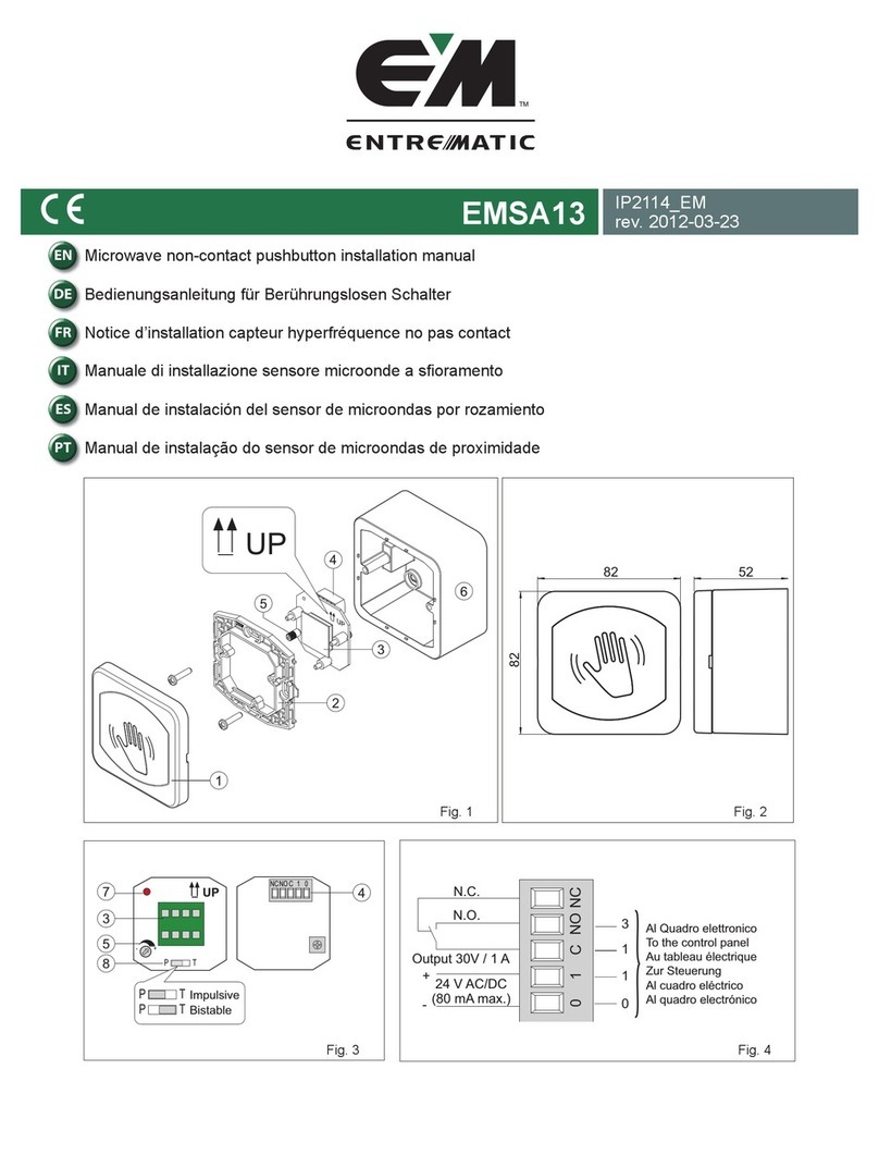
IMS ROBOTICS DRIVEplus User manual

1

2

3
Information about the machine
Designation: IMS Cutter DRIVEplus
Manufacturer: IMS Robotics GmbH
Am Bauhof 6
01458 Ottendorf-Okrilla
Tel: +49 (0)35205/75550
Fax: +49 (0)35205/53749
Email: info@ims-robotics.de
http://www.ims-robotics.de
User information: As of 15/03/2022
Translation
Item number: 034 17 000

4
Foreword
The user information is intended to help the operator to work safely and properly and to
maintain the IMS devices. It is therefore essential to pay attention to this manual.
Note
The accident prevention regulations and general safety rules must be observed when
operating the device.
Important instructions, such as safety-related instructions, are marked
with appropriate symbols. Follow these instructions to avoid accidents
and damage to the devices.
Liability and Warranty
All information and instructions for the operation and maintenance of the milling machine have
been provided to the best of our knowledge, taking into account the experience and knowledge
we have gained so far.
We reserve the right to make technical changes as part of the further development of the
device covered in this operating manual. During the warranty period, repairs and modifications
to the system may only be carried out by the manufacturer or on his instructions. Otherwise,
liability and the warranty for the entire device will be void.

5
Table of Contents
1Intended Use................................................................................................................ 9
2Technical Information ................................................................................................10
2.1 Technical data.......................................................................................................10
2.2 Main dimensions...................................................................................................11
3General Safety Rules..................................................................................................12
4Description and Setting Instructions ........................................................................13
4.1 Overview of the assemblies ..................................................................................13
4.2 General description...............................................................................................15
4.3 Controller ..............................................................................................................15
4.3.1 Controller in general........................................................................................15
4.3.2 Operating elements on the controller...............................................................15
4.3.3 Connections on the controller..........................................................................18
4.3.4 Start screen.....................................................................................................20
4.3.5 Selecting the Configuration .............................................................................21
4.3.6 Milling menu....................................................................................................23
4.3.6.1 Meter counter...........................................................................................23
4.3.6.2 Undercarriage ..........................................................................................23
4.3.6.3 Carriage ...................................................................................................24
4.3.6.4 Cable drum ..............................................................................................24
4.3.6.5 Tighten the cable......................................................................................24
4.3.6.6 Milling arm position ..................................................................................25
4.3.6.7 Velocity ....................................................................................................25
4.3.6.8 Icons in the footer bar...............................................................................25
4.3.7 Settings menu .................................................................................................26
4.3.7.1 Parameter list...........................................................................................27
4.3.7.2 Configuration............................................................................................28
4.3.7.3 System information ..................................................................................29
4.3.7.4 Joystick Config.........................................................................................30
4.4 Operation touch monitor with video software.........................................................35
4.4.1 Monitor............................................................................................................35
4.4.2 Starting the video software..............................................................................35
4.4.3 Overview of the individual buttons in the footer bar .........................................37
4.4.4 Explanation of the individual buttons ...............................................................38
4.4.4.1 Video player menu ...................................................................................38
4.4.4.2 Loading and playing a stored video or image file......................................39
4.4.4.3 Record button ..........................................................................................41
4.4.4.4 "Camera" button.......................................................................................41
4.4.4.5 "Text overlays" button ..............................................................................41

6
4.4.4.6 "Minimise" button .....................................................................................41
4.4.4.7 "Settings" button.......................................................................................42
4.4.4.7.1 Basic settings.......................................................................................42
4.4.4.7.2 Text overlay .........................................................................................43
4.4.4.8 Select Language and unit.........................................................................44
4.4.4.9 Service menu ...........................................................................................44
4.4.4.10 Information menu .....................................................................................45
4.5 Cable drum ...........................................................................................................46
4.5.1 Overview.........................................................................................................46
4.5.2 Explanation of the operating elements of the cable drum ................................46
4.5.3 Mounting roll arm on the cable drum ...............................................................49
4.5.4 Water equipment.............................................................................................50
4.5.4.1 Water equipment with 2 liter water tank....................................................50
4.5.4.2 Connection of water tank (optional) to cable drum....................................51
4.6 Safety regulations .................................................................................................52
4.7 Control box with operating elements and connections...........................................53
4.7.1 Control box in general .....................................................................................53
4.7.2 Explanation for control elements and connections on control box....................54
4.7.2.1 Fan...........................................................................................................54
4.7.2.2 Analog video output .................................................................................54
4.7.2.3 Anschluss Handbedienteil Extern.............................................................54
4.7.2.4 Motor cable drum .....................................................................................54
4.7.2.5 Connection renovation system .................................................................55
4.7.2.6 Socket cable drum connection .................................................................55
4.7.2.7 Controller port ..........................................................................................55
4.7.2.8 Main switch ..............................................................................................55
4.7.2.9 Release button.........................................................................................56
4.7.2.10 "Operational"/"ready for use"....................................................................56
4.7.2.11 "Emergency Stop" lamp ...........................................................................56
4.7.2.12 Emergency stop switch ............................................................................56
4.7.2.13 Emergency mode "Drive" .........................................................................57
4.7.2.14 Emergency mode "Turn" ..........................................................................57
4.7.2.15 Emergency mode "Swivel" .......................................................................57
4.7.2.16 Key switch "Emergency mode".................................................................58
4.7.3 Explanation external hand-held control unit.....................................................59
4.7.3.1 Connection cable with plug of the hand-held control unit..........................59
4.7.3.2 Emergency Switch of the hand-held control unit.......................................59
4.7.3.3 Switch for the electrical coupling of the hand-held control unit..................60
4.7.3.4 Signal lamp electrical coupling of the hand-held control unit.....................60
4.7.3.5 Controlling the trolley with the hand-held control unit ...............................60

7
4.7.3.6 Controlling the milling arm with the hand-held control unit........................60
4.7.3.7 Controlling the cable drum with the hand-held control unit .......................61
4.7.3.8 Connection of the hand control to the control cabinet...............................61
4.8 Robot ....................................................................................................................62
4.8.1 Carriage ..........................................................................................................62
4.8.1.1 Pressure rail.............................................................................................62
4.8.1.2 Reverse travel safety device ....................................................................63
4.8.2 Cutting arm .....................................................................................................63
4.8.3 Swivel-head camera........................................................................................64
4.8.4 Swivel-head camera with wiper (optional) .......................................................65
4.8.5 Equipment options ..........................................................................................66
4.8.5.1 Circular profile undercarriage DN 450-600 ...............................................66
4.8.5.2 Electric swivel drive for milling motor........................................................67
5Operating manuals .....................................................................................................68
5.1 Energy supply .......................................................................................................68
5.2 Start up .................................................................................................................69
5.3 Operation..............................................................................................................69
5.3.1 Operating the milling robot ..............................................................................69
5.4 Conversion to other nominal diameters.................................................................70
5.4.1 Extension parts and nominal diameter dependent assembly of the DRIVEplus
carriage and the pressure rail .......................................................................................70
5.4.1.1 Overview of extension parts of the carriage..............................................70
5.4.1.1.1 Assembly corundum and granulated wheels ........................................72
5.4.1.2 Mounting the undercarriage......................................................................73
5.4.1.3 Overview of extension parts of the pressure rail.......................................74
5.4.1.4 Nominal diameter dependent assembly ...................................................75
5.5 Crane Connection.................................................................................................77
5.6 Changing the milling motor ...................................................................................78
5.7 Milling tools ...........................................................................................................79
5.7.1 Changing milling tool of the small air motor.....................................................80
5.7.2 Changing the milling tool of the large air motor................................................80
5.8 Pressure monitoring..............................................................................................81
5.8.1 Monitoring mode .............................................................................................81
5.8.2 Checking the carriage and cutting arm after completing the work....................82
6Repair and Maintenance.............................................................................................83
6.1 Cleaning................................................................................................................83
6.2 Transport ..............................................................................................................83
6.3 Care and maintenance..........................................................................................83
6.3.1 Media supply line ............................................................................................83
6.3.2 Milling motor....................................................................................................84

8
6.3.2.1 Ball bearing and fins of the large air motor ...............................................84
6.3.2.1.1 Ball bearing..........................................................................................84
6.3.2.1.2 Replace the fins ...................................................................................84
6.3.2.2 Ball bearing and blades of the small air motor..........................................86
6.3.2.2.1 Overview of spare parts .......................................................................86
6.3.2.2.2 Disassembling and reassembling the air motor....................................87
6.3.3 Milling arm/ swivel drive gear - oil change .......................................................90
6.3.3.1 Open the screw plug ................................................................................91
6.3.3.2 Drain the transmission oil .........................................................................92
6.3.3.3 Fill transmission oil...................................................................................93
6.3.3.4 Close the screw plug................................................................................94
6.3.3.5 Cable drum ..............................................................................................94
6.3.4 Nitrogen filling .................................................................................................95
6.3.5 Set up Internet access for remote maintenance "PC" ......................................97
7Additional Regulations to be followed ......................................................................98
8Overview accessories ................................................................................................99
9EC-Declaration of Conformity..................................................................................100

9
1 Intended Use
The operational safety of the system supplied is guaranteed only if it is used as intended.
Intended use includes compliance with the regulations laid down in this operating manual and
performance of all scheduled maintenance and service work.
The IMS milling machine DRIVEplus may be used only for the execution of milling work for the
purpose of rehabilitating unpressurised pipes or lines. The device can be used to open inliners
after renovation and remove obstacles (roots, protruding seals, small misalignments, etc.). The
machine may not be used for any other purpose.
Unauthorised structural changes to the system can lead to damage to the machine and pose
a danger to persons. IMS shall not be liable for any resulting damage. In the event of damage,
responsibility remains with the operator and cannot be transferred to IMS.

10
2 Technical Information
2.1 Technical data
System components Carriage
Cutting arm DRIVEplus
Swivel-head colour camera
Controller
Cable drum
Extension carriages 1
Extension parts for axles and pressure rail
Accessories
Driving speed: max. 10 m/min with wheel D=140 mm
Format: Pipes of the nominal diameter 150 mm (without coupling
displacement/misalignment) with extension
undercarriage/extension parts up to 600 mm pipe nominal
diameter
Change of nominal diameters: depending on the nominal diameter, between approx. 10 and
approx. 20 min
Electricity: 100-240 V +/-1% /50-60 Hz/1000 W
Weight: DRIVEplus - milling machine without extensions: approx. 38 kg
Extension carriage: approx. 11 kg
Extensions complete: approx. 23 kg
Cable drum: approx. 165 kg
Control box: approx. 36 kg
Controller: approx. 10 kg
Compressed air: Consumption: approx.1,6 m3/min
Supply pressure: 8 bar
Quality: filtered, dry
max. 40C
Caution! Contaminated and moist air will damage the air motor and
the seals on the robot.
Workstation: at the control panel
Temperature range: +5 ... +40C
Caution! Do not operate the controller in the event of large
temperature fluctuations (condensate) or outdoor precipitation!
Media supply line: 100 m on a cable drum
Camera signal: PAL

11
2.2 Main dimensions
Carriage with cutting arm:
Device designed for pipes of 200 mm nominal diameter:
1114 mm

12
3 General Safety Rules
CAUTION!
The device may be operated only by persons who have been instructed
in its use. Inadequate knowledge can cause damage to the device or
danger to the operator.
CAUTION!
Pull out the mains plug before opening the devices.
CAUTION!
When lowering the individual parts or the entire robot, it is forbidden for
persons to be in the shaft or under the suspended load.
The accident prevention regulations for working in pipelines, earth-
moving machines, winches, lifting and pulling equipment and the safety
regulations for pipeline construction work must be observed.

13
4 Description and Setting Instructions
4.1 Overview of the assemblies
Overall view
1
Carriage
7
Cutter air hose
2
Crane attachment
8
Water nozzle for camera
3
Wheels - pressure rail
9
Electric swivel drive
4
Pressure rail
10
Nitrogen valve - carriage
5
Swivel-head camera with nitrogen
valve
11
Reverse travel sensor
6
Cutting arm
12
Electrical connection - reverse travel
camera
8 9 10 11 12
1 2 3 4 2 5 6 7 8 9

14
13
Nitrogen valve - camera
17
Controller with monitor
14
Nitrogen valve - cutting arm
18
Cable drum
15
Water nozzle
19
Foot pedal
16
Locking screw - swivel drive
20
External control unit
13 14 15 16
18
19 20
17

15
4.2 General description
The IMS milling machine DRIVEplus is a device for execution of milling work for the purpose
of cleaning and repairing sewers and for opening inlets after rehabilitation. By using extension
parts, the basic version can be upgraded from nominal diameter 150 mm to nominal diameter
600 mm (depending on scope of delivery). The total length of the device can be reduced for
insertion into the shaft by bending the cutting arm and setting it straight only when inserted.
In general, ensure that all devices are stored frost-free.
4.3 Controller
4.3.1 Controller in general
All components of the milling machine are operated via the controller.
All control panels and operating elements are described in detail in the following sections.
4.3.2 Operating elements on the controller
The controller has an emergency stop switch, 2 multi-function joysticks and a touchscreen
interface.

16
When faults occur, an acoustic warning signal is sounded. When the fault
is acknowledged, the warning signal is turned off.
In the event of an accident or fault, press the emergency stop switch. The
system is now no longer operational. The red indicator lamp for
“emergency stop”is now lit. To release the emergency stop switch, turn it
slightly to the left or right. Do not pull the emergency stop switch. This will
destroy the switch.
In order to start the video PC, press the corresponding button on the
controller for 16pprox.. 3 seconds. The button is then illuminated in green.
USB port, to connect a keyboard or computer mouse or a mass storage
device.
The multifunction joysticks have 3 control axes. This means that the
joysticks can be dynamically moved to the left, right, forward and
backwards. The handle of the joystick itself can be turned dynamically to
the left and right. There are also 2 buttons on the handle which can be
used as switches or buttons, depending on the application.

17
The operator interface is a touch panel. All control and regulating elements are activated or
deactivated by pressing or swiping on the interface.

18
4.3.3 Connections on the controller
Top view of the controller
1
USB port with blind cover (for service technicians only).
2
USB port, to connect a keyboard or computer mouse or a mass storage device to
store image or video files.
1
2

19
Rear view of the controller
1
Analog video signal port
2
1x USB port, to connect a Monitor
3
HDMI port - Monitor
4
Power supply - Monitor
5
Fastening for Monitor bracket
6
Network port (for service technicians only)
7
Port to connect Controller to Control Box
1 2 3 4 5 6 7

20
4.3.4 Start screen
After the system has been switched on, the controller is started. This process takes
approximately 20 sec. Then the following start screen appears.
The following buttons are available:
The "Milling" menu opens.
A submenu opens from which all settings can be made.
A submenu opens in which the language can be set.
Table of contents
Other IMS ROBOTICS Industrial Equipment manuals
Popular Industrial Equipment manuals by other brands
EGAmaster
EGAmaster 55815 operating instructions
Black Box
Black Box EVSW240-100 instruction manual
Ebmpapst
Ebmpapst D3G250-EF41-01 operating instructions

Gema
Gema PH300 Operating instructions and spare parts list
woodmizer
woodmizer CBT-430 Safety, Operation, Maintenance & Parts Manual

Little Giant
Little Giant BS2448PBHP-K owner's manual

OEM Tools
OEM Tools 87032 Operating instructions and parts manual
Alfalaval
Alfalaval T2 instruction manual

Power Fist
Power Fist 8873341 quick start guide
woodmizer
woodmizer MP260EA13U-V manual
woodmizer
woodmizer LT40AC Remote - ST Operator's manual
woodmizer
woodmizer LASTEC 621ER Product information bulletin
