Little Giant BS2448PBHP-K User manual

INTRODUCTION
These instructions are for the typical installation of a Little Giant
Pump Company Basin Package System. This package system
includes a rugged polyethylene or fiberglass basin, equipped with
either a guide rail system for easy access to the pump or a
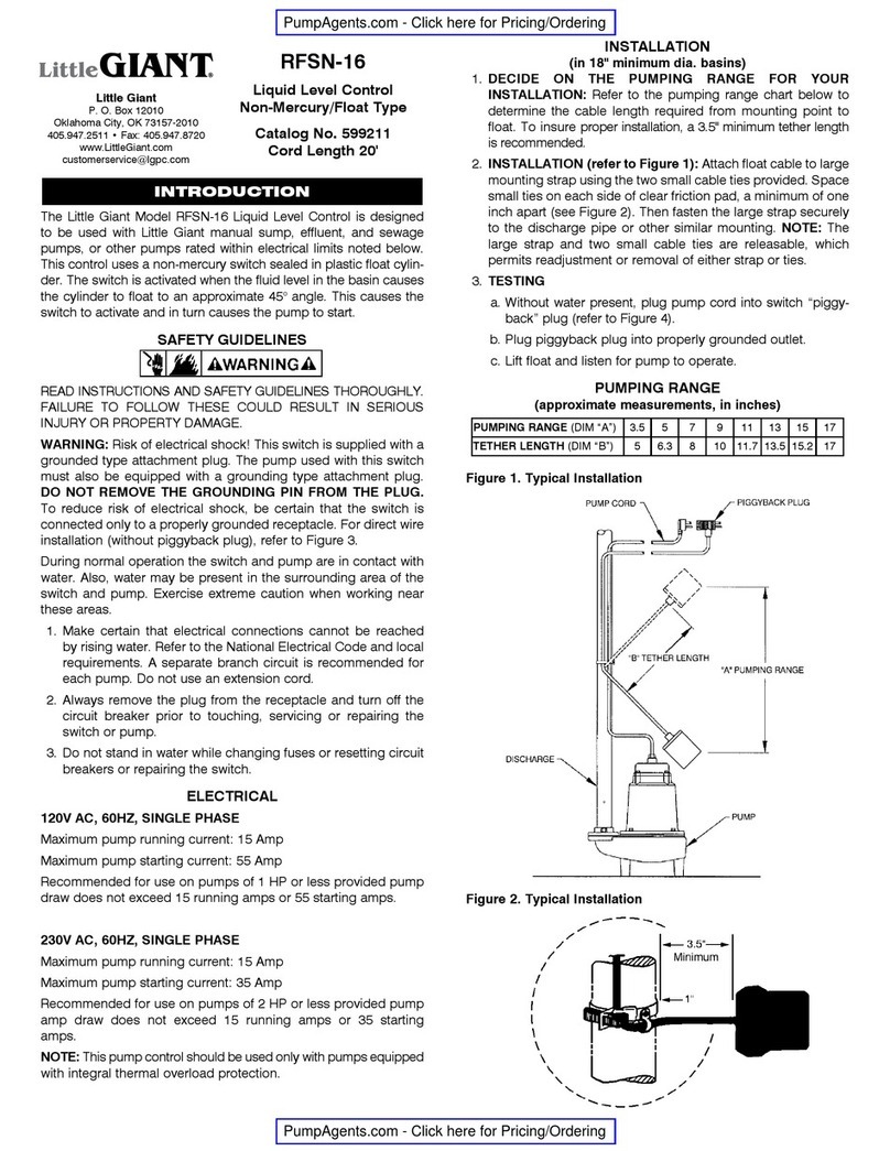
hard-piped system. The inlet to the basin is to be field installed (see
Figures 2 and 4) and uses a 4" Adapt-A-Flex fitting. The hole for
routing of the electrical cord(s) is to be field installed (See Figures 2
and 4) and uses a 2" Adapt-A-Flex fitting. These fittings are
constructed from neoprene plastic, are easy to install and require
no sealants. This design has boltless vapor and water leakproof
sealing ability.
I. BASIN INSTALLATION INSTRUCTIONS
(See Figure 3)
1. Inspect all materials supplied by and/or installed by Little Giant
Pump Company to assure there are no damages due to
shipping prior to installation.
2. Excavate hole large enough to accommodate basin, usually 12" –
18" larger than the diameter of the basin, and 4"- 6" deeper than the
basin depth. Also, hole should be able to accommodate under
ground piping, backfill material and adequate working space.
3. Prepare the bottom of the excavated hole with 4" - 6" of backfill
material or concrete pad. Check base to insure it is level and
smooth.
4. Install basin on gravel base or concrete pad. Anchor down if
necessary. Basin to be installed only in vertical position.
5. For fiberglass basins, concrete may be poured around bottom
basin bottom if ballast is required for buoyancy.
6. Plumb all inlet and discharge piping as well as the electrical
piping for internal junction box (Not Included). Inlet pipe is
recommended to be 4" Schedule 40 PVC to accommodate 4"
Adapt-A-Flex fitting (see Figure 2 and step 5 for installation tips).
Discharge piping for the pump and electrical cords is
recommended to be either Schedule 40 or 80 1-1/4" PVC piping,
depending on local codes and installer recommendation (see
Figure 1). Basin is to be vented per local plumbing codes.
7. Backfill with pea gravel 4" to 6" around the entire periphery of
the basin. Compact backfill material in 12" lifts. Stop and
connect piping as required. If using concrete as backfill on
poly-basin, the basin should be filled with water to provide
support and stabilization.
RECOMMENDED BACKFILL MATERIAL
Gravel or stone to be free flowing, naturally round aggregate
with a particle size of not less than 1/8" and not greater than 3/4"
in diameter.
CAUTION: Do not bury basin deeper than basin height. In freezing
conditions backfill material must be dry and free of ice.
II. PUMP INSTALLATION
RAIL SYSTEM BASINS
1. Fully thread the nut onto discharge pipe. Place lower guide rail
onto discharge pipe, below the nut (See Figure 1).
2. Apply teflon tape to discharge pipe threads. Thread discharge
pipe into pump discharge until disconnect and pump are
oriented as shown (See Figure 4). Make sure that the discharge
pipe is tight.
3. With discharge pipe installed, orient lower guide rail as shown in
Figure 4 and tighten nut. The lower guide rail should now be in
alignment with the upper guide rail.
4. Attach the lifting chain to the clevis and eye bolt. Attach chain to
wire handle on pump and eye bolt on disconnect.
5. Determine the center of gravity of pump by making adjustments
to the clevis location on the chain.
6. Lift pump and lower down into basin.
7. Position pump so the lower guide is aligned with the rail. Slowly
lower pump into basin and position upper guide so that it is
aligned with the rail (See Figure 4).
8. Pump and disconnect assembly should slide rail down until the
disconnect is seated.
9. Make appropriate electrical connections and mount junction
box at desired location.
HARD-PIPED BASINS
NOTE: HARD-PIPED INSTALLATIONS REQUIRE USE OF THE
LITTLE GIANT GRINDER LEG KIT
1. Install Little Giant Grinder Leg Kit on pump.
2. Apply teflon tape to discharge pipe assembly.
3. Thread discharge pipe into discharge of pump.
4. Attach lifting chain to the clevis and then attach to the wire
handle on top of pump.
5. Lift pump and lower down into basin.
6. Orient the pump assembly as shown (See Figure 4) and connect
the assembly to the pipe fitting in basin.
7. Make appropriate electrical connections and mount junction
box, if needed, at desired location.
III. JUNCTION BOX WIRING
(JUNCTION BOX NOT INCLUDED)
All wiring connections coming from the pump and/or to the control
panels should be made within a junction box in accordance with
national, state, local and NEC codes where applicable.
Little Giant Pump Company
3810 North Tulsa Street
Oklahoma City, Oklahoma 73112
405.947.2511 • FAX 405.947.8720
Little
Pump Company
GIANT
OWNERS MANUAL
For Little Giant®
BASIN PACKAGE SYSTEMS
A-L125
FIG. 1
BS2448PBHP-K•BS2448FGHP-K•BS2460PBHP-K
BS2460FGHP-K•BS2448PBRS-K•BS2448FGRS-K
BS2460PBRS-K•BS2460FGRS-K•BS2472PBRS-K
BS2472FGRS-K•BS2484PBRS-K•BS2484FGRS-K

NOTE: If using a Little Giant Pump Company manual grinder
pump and control panel in combination with this basin
package system, then refer to wiring section of the Little Giant
Pump Company control panel instruction sheet for additional
details on wiring pump and panel in conjunction with junction
box in this basin. If using pump and control panel other than
from Little Giant Pump Company, refer to the appropriate
section of the pump and/or control panel instruction sheet(s)
for completion of the wiring of components.
IV. ADAPT-A-FLEX INSTALLATION INSTRUCTIONS
(See Figure 2)
Adapt-A-Flex fittings are constructed from neoprene plastic, are
easy to install and require no sealants. The Adapt-A-Flex design
has boltless and water leakproof sealing ability.
4" Adapt-A-Flex seal (for inlet):
1. Using a 5.0" hole saw, cut an opening in tank sidewall and seat
Adapt-A-Flex fitting as shown.
2. For ease of installation chamfer ends of pipe before inserting
through the Adapt-A-Flex.
3. Lubricate pipe with soapy water and insert as shown.
2" Adapt-A-Flex seal (for electrical):
1. Using a 3.0" hole saw, cut an opening in tank sidewall and seat
Adapt-A-Flex fitting as shown.
2. For ease of installation chamfer ends of pipe before inserting
through the Adapt-A-Flex.
3. Lubricate pipe with soapy water and insert as shown.
FIG. 2
2

3

LIMITED WARRANTY
Little Giant Basin Systems are suitable for housing, residential sewage and other non-explosive, non-corrosive, non-abrasive liquids no t
above 140°F.
Your Little Giant product is guaranteed to be in perfect condition when it leaves our Factory. It is warranted against defective materials and
workmanship for a period of 12 months (90 day warranty on Models: 1-AA-OM, GKPK-SC, PP-1, PPS-1, PP-12, PPS-12 , PP-230 and
Cooler King) from date of purchase by the user. No warranty on brush wear in Model 35-OM and impeller or cam in Models PP-1, PP-12,
and PP-230.
Any product that should fail for either of the above two reasons and is still within the warranty period will be repaired or replaced at the
option of Little Giant as the sole remedy of buyer. For our customers in the CONTINENTAL UNITED STATES: Please return the defective
unit, postage paid, to the factory at 301 N. MacArthur, Oklahoma City, OK 73127-6616. All defective product returned under warranty will
be fully inspected to determine the cause of failure before warranty is approved.
For our customers located elsewhere; it is not economical, due to duties and freight, to return the pump to the factory for inspection.
Please return the defective unit to any authorized distributor or dealer with a brief written explanation of the problem. If there are no
apparent signs of customer abuse, unit will be repaired or replaced. If dispute arises over replacement of the pump, the distributor or
dealer is to segregate such items and hold for inspection by a representative of Little Giant Pump Company or notify factory with details of
the problem for factory disposition and settlement of warranty claim.
DISCLAIMER:
THE FOREGOING WARRANTY IS AN EXCLUSIVE WARRANTY IN LIEU OF ANY OTHER EXPRESS WARRANTIES. ANY IMPLIED
WARRANTIES (INCLUDING, BUT NOT LIMITED TO ANY IMPLIED WARRANTY OF MERCHANTABILITY OR FITNESS FOR A
PARTICULAR PURPOSE) TO THE EXTENT EITHER APPLIES TO A PUMP SHALL BE LIMITED IN DURATION TO THE PERIODS OF THE
EXPRESS WARRANTIES GIVEN ABOVE.
Warranty will be VOID if any of the following conditions are found:
1. Sealed motor housing opened.
2. Product connected to voltage other than indicated on nameplate.
3. Cord cut off to a length less than three feet.
4. Pump allowed to operate dry (fluid supply cut off).
5. Pump used to circulate anything other than fresh water, light oils, or other mild liquids at approximately
room temperature.
6. Product abuse by customer.
Any oral statements about the product made by the seller, the manufacturer, the representatives or any other parties, do not constitute
warranties, shall not be relied upon by the user and are not part of the contract for sale. Seller’s and manufacturer’s only obligation, and
buyer’s only remedy, shall be the replacement and/or repair by the manufacturer of the product as described above. NEITHER SELLER
NOR THE MANUFACTURER SHALL BE LIABLE FOR ANY INJURY, LOSS OR DAMAGE, DIRECT, INCIDENTAL OR CONSEQUENTIAL
(INCLUDING, BUT NOT LIMITED TO INCIDENTAL OR CONSEQUENTIAL DAMAGES FOR LOST PROFITS, LOST SALES, INJURY TO
PERSON OR PROPERTY, OR ANY OTHER INCIDENTAL OR CONSEQUENTIAL LOSS), ARISING OUT OF THE USE OR THE INABILITY
TO USE THE PRODUCT AND THE USER AGREES THAT NO OTHER REMEDY SHALL BE AVAILABLE TO IT. Before using, the user shall
determine the suitability of the product for the intended use, and user assumes all risk and liability whatsoever in connection therewith.
Some states and countries do not allow limitations on how long an implied warranty lasts or the exclusion or limitation of incidental or
consequential damages, so the above limitations or exclusions may not apply to you. This warranty gives you specific legal rights, and
you may also have other rights which vary from state to state and country to country.
The National Electric Code (in the USA) and similar codes in other countries require a Ground Fault Circuit Interrupter (GFCI) to be
installed in the branch circuit supplying fountain equipment rated above 15 volts. 115 volt GFCI’s (with various cord lengths) are in stock,
and we recommend each pump be used with a GFCI.
©Copyright 2003 Little Giant Pump Company FORM 998185 — 03/03:
Printed by Little Giant DocServ
This manual suits for next models
11
Other Little Giant Industrial Equipment manuals


