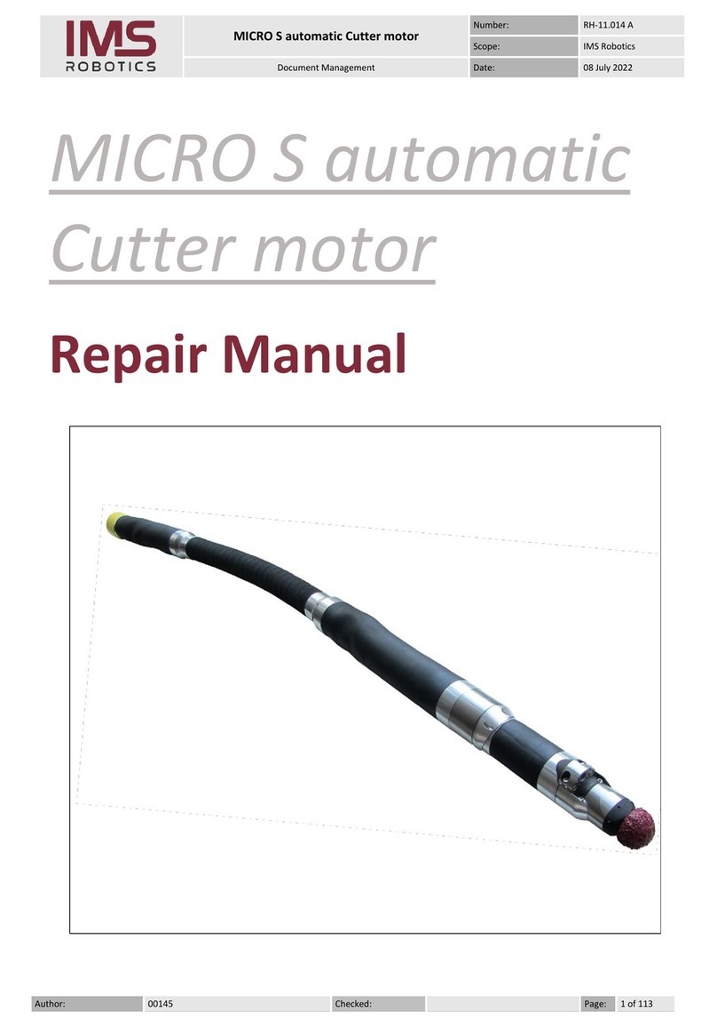
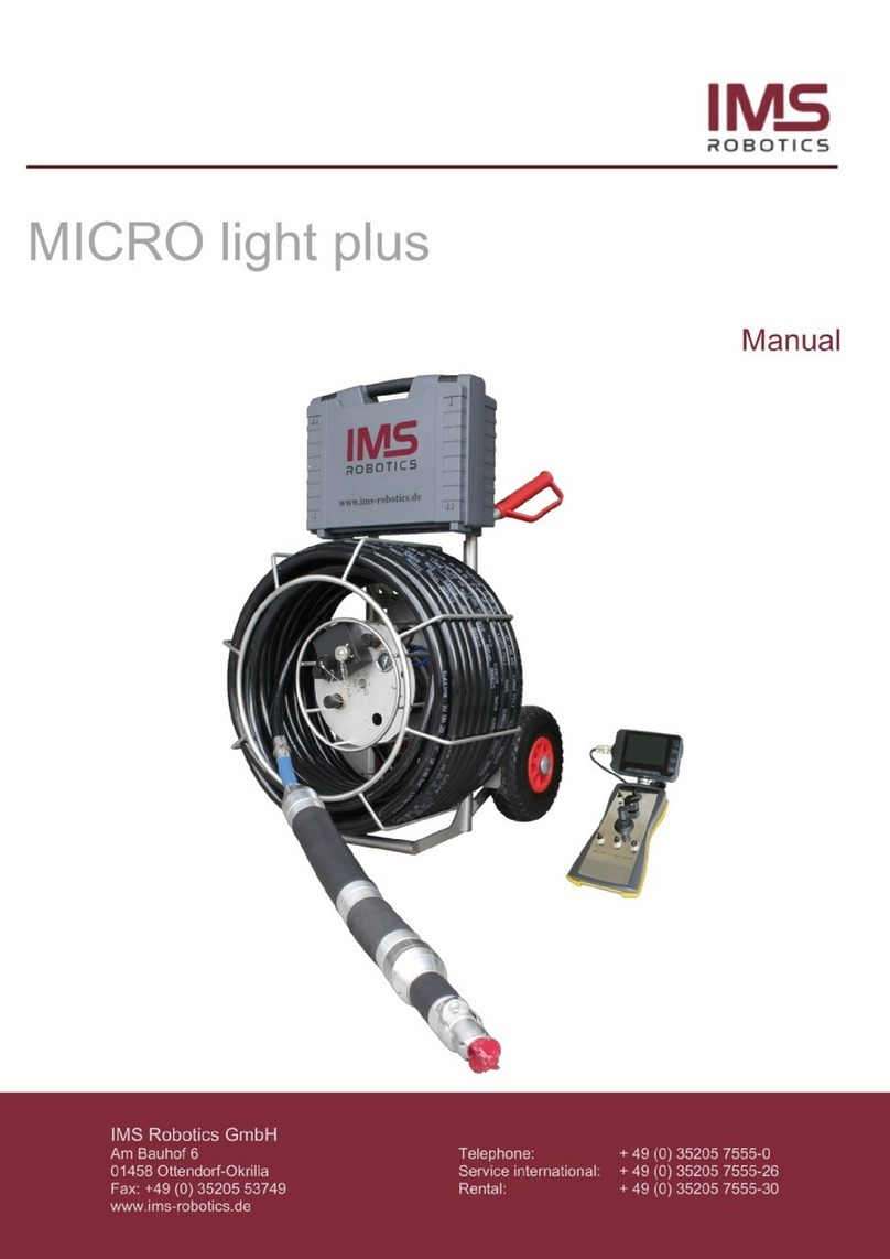
IMS ROBOTICS DRIVE plus Operating instructions

DRIVE plus carriage and cutter drive
Number:
RH-11.010.A
Scope:
IMS Robotics
Document managment
Date:
28.03.2022
Created:
00145
Checked:
00047
Page:
1 of 8
DRIVE plus
carriage und cutter drive
Repair manual

DRIVE plus carriage and cutter drive
Number:
RH-11.010.A
Scope:
IMS Robotics
Document managment
Date:
28.03.2022
Created:
00145
Checked:
00047
Page:
2 of 8
Foreword
This Repair Manual provides the technical description of our cutter motors and important
information to have them independently repaired by professionals.
We recommend reading the Repair Manual thoroughly before carrying out the respective
repairs.
IMS Robotics GmbH owns all rights to this Repair Manual as well as to its enclosures/pictures.
All details and information are entrusted to the recipient for personal use only.
Information from this Repair Manual must not be disclosed or handed over to third parties, in
particular, to competitors. Therefore, reproduction of this Repair Manual in any form is not
permitted.
Liability
IMS Robotics GmbH assumes no liability for direct damage or consequential damage resulting
from improper repair.
In addition, please use only spare parts supplied by IMS Robotics GmbH. IMS Robotics GmbH
also assumes no liability for the use of other products and any resulting damage.
IMS Robotics GmbH reserves the right to make changes to this Repair Manual at any time and
without notice in the event of any technical or typing errors contained in it.

DRIVE plus carriage and cutter drive
Number:
RH-11.010.A
Scope:
IMS Robotics
Document managment
Date:
28.03.2022
Created:
00145
Checked:
00047
Page:
3 of 8
Table of contents
Preface ....................................................................................Fehler! Textmarke nicht definiert.
Liability ...............................................................................................Fehler! Textmarke nicht definiert.
1. Removal and assembly instructions.................................................................................................... 3
2. Dismanteling of the carriage ............................................................................................................... 4
3. Assembly of the carriage..................................................................................................................... 7
4. Resources ............................................................................................................................................ 8
1. Removal and assembly instructions
•When dismantling the carriage to replace the drive shaft (034 11 312), the cutter arm can
and should remain mounted on the carriage. The cutter arm serves as a "lever" when pulling
the cover off the housing. Great care must be taken to ensure that the sealing surfaces and
above all, the O-ring are not damaged.
➢If the O-ring is damaged, the cutter arm must be detached from the carriage and all
cable connections disconnected. This is the only way to mount a new O-ring.
•Remove the housing cover (011 35 310) a maximum of 100 mm from the housing (011 42
623), otherwise the cabling can be damaged.
•When dismantling and assembling, always make sure that no cables or hoses are pinched or
damaged.
➢When reassembling everything must be fastened back in the same way as it was
before dismantling. (Photo documentation of the condition before dismantling)
•Check sealing surfaces and O-rings for intactness before assembly.
•When assembling, clean all sealing surfaces and bearings with brake cleaner or white spiritus
and grease again if necessary.
•Re-grease all moving parts.
•Secure all screw connections with Loctite 274 blue.

DRIVE plus carriage and cutter drive
Number:
RH-11.010.A
Scope:
IMS Robotics
Document managment
Date:
28.03.2022
Created:
00145
Checked:
00047
Page:
4 of 8
2. Disassembly of the carriage
1. Dismantling the pressure bar
2. Dismantling of the cutting air hoses and
the associated swivel screw
connections
3. Disassembly of the housing cover
4. Removing the cover 1
Attention
The cover is produced in 3D printing
and is very fragile

DRIVE plus carriage and cutter drive
Number:
RH-11.010.A
Scope:
IMS Robotics
Document managment
Date:
28.03.2022
Created:
00145
Checked:
00047
Page:
5 of 8
5. Loosen the fastening screws on the
housing cover (6 pieces in total)
Before removing the cover from the
housing, the ring nut must be brought into
the appropriate position by turning the
cutting arm.
blob:file:///cdd06f6b-ef26-4a8a-a5a5-
38d740b815e6
Attention
The screws are secured with Loctite 274
blue during manufacture and can be
heated with a heat gun for better
dismantling
Attention
When separating the cover from the
housing, observe the assembly instructions.
Should it be necessary to use a lever tool
between the cover and the housing, only
lever it at the points where the O-ring
cannot be damaged.
wrong
right

DRIVE plus carriage and cutter drive
Number:
RH-11.010.A
Scope:
IMS Robotics
Document managment
Date:
28.03.2022
Created:
00145
Checked:
00047
Page:
6 of 8
In the sectional drawing you can see the position of the shaft (1) with the associated
Gears (2, 3) and the two ball bearings (4, 5).
A = Cover (011 35 310)
B = Housing (011 42 623) (Unfortunately no longer available in the 3D image)
Shaft via the gear on
fix the bearing flange
6. Loosen both fitting screws on the left
and right of the housing to loosen the
bearing flange
A 4 2 1 3 5 B
Tipp
When the two parts (housing and cover) are separated, the axle (1) is pulled out of the
bearing (4). The bearing remains in the cover, the axle (1) and the gear (2) are separated
from the cover and remain in the housing.
In order to protect the gear (3) and the bearing (5) from damage during this operation,
the shaft should be held towards the housing.
Bearing flange

DRIVE plus carriage and cutter drive
Number:
RH-11.010.A
Scope:
IMS Robotics
Document managment
Date:
28.03.2022
Created:
00145
Checked:
00047
Page:
7 of 8
7. Set the bearing flange at a slight angle
8. Pull the axle together with the ball
bearing out of the flange
3. Assembley of the carriage
New SBG drive shaft to be installed 1
(034 11 312)
completely laser-welded with pinion
•Check the drive shaft and correct any irregularities.
Attention! Pinions must be free of machining residues and impacts
•Assemble the drive shaft and the carriage in reverse order to disassembly
•Observe the assembly instructions from Section 1
Hint
If the ball bearing is not damaged, it can
be used again. If it is new - deep groove
ball bearings (030 01 071)

DRIVE plus carriage and cutter drive
Number:
RH-11.010.A
Scope:
IMS Robotics
Document managment
Date:
28.03.2022
Created:
00145
Checked:
00047
Page:
8 of 8
4. Resources
Loctite 274 (blue)
For securing screw connections
Petrol or brake cleaner
for degreasing and cleaning all metallic
parts
Table of contents
Other IMS ROBOTICS Robotics manuals
