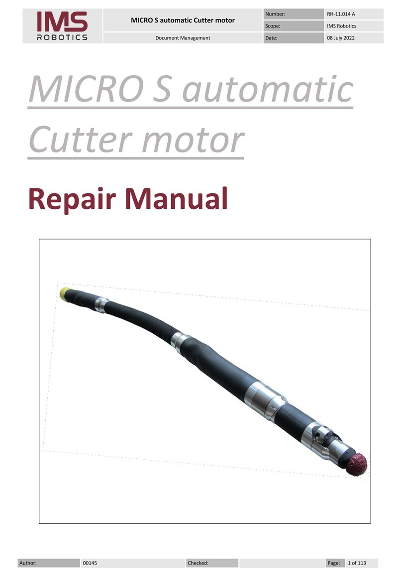
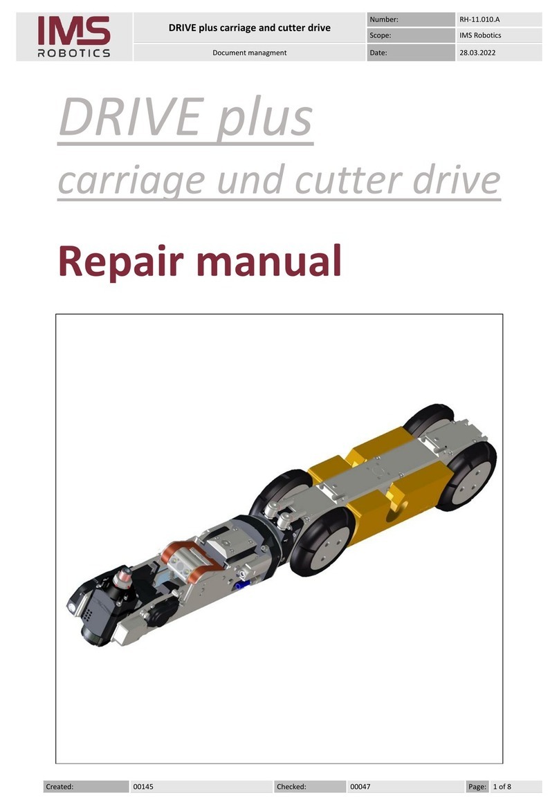
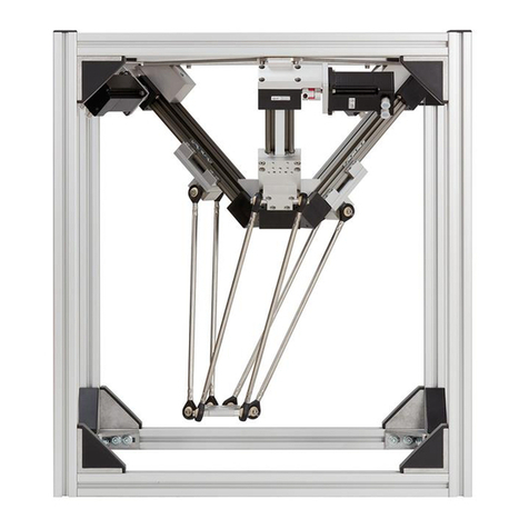
IMS ROBOTICS MICRO light plus User manual

1

2

3
Information of the device
Designation: MICROlight plus
Manufacturer: IMS Robotics GmbH
Am Bauhof 6
01458 Ottendorf-Okrilla
Tel.: +49 (0)35205-75550
Fax: +49 (0)35205-53749
E-Mail:info@ims-robotics.de
Website: www.ims-robotics.de
User information: State 31.03.2022
Translation of the original instruction
Article number: 031 10 000

4
Table of contents
1Intended use ................................................................................................................ 6
2Operation ..................................................................................................................... 7
2.1 General ................................................................................................................... 7
2.2 Start-up ................................................................................................................... 9
2.2.1 Fasten the fiberglass push rod ........................................................................12
2.2.2 Assembly and nominal width-depended setup of extension ring......................14
2.2.3 Control unit MICROlight plus ...........................................................................16
2.3 Operation during work ............................................................................................17
2.3.1 Operation IMS Cutter MICROlight plus............................................................17
2.3.2 Recovering the cutter in case of malfunction ...................................................18
2.4 Finishing work ........................................................................................................19
2.5 Cutting tools ...........................................................................................................20
2.5.1 Overview of cutting tools .................................................................................21
2.5.2 Changing the cutting tool.................................................................................22
3Safety regulations.......................................................................................................23
3.1 General regulations................................................................................................23
3.2 Special regulations.................................................................................................23
4Maintenance and repair..............................................................................................24
4.1 Cleaning and transportation ...................................................................................24
4.2 Care and maintenance ...........................................................................................24
4.2.1 Cleaning the camera cleaning ring ..................................................................25
4.3 Pressure monitoring ...............................................................................................26
4.3.1 Function check................................................................................................26
4.3.2 Pressure monitoring drive ...............................................................................26
4.3.3 Inspection after completion of work .................................................................26
4.3.4 Nitrogen refilling ..............................................................................................27
4.4 Checking the pressure reducer...............................................................................29
4.4.1 Checking the pressure reducer for the stroke drive .........................................29
4.4.2 Checking the pressure reducer for the bracing bubble ....................................30
4.4.3 Check the pressure reducer for axial bladder ..................................................31
5Repairs ........................................................................................................................32
5.1 Repair, replacement or spare part? ........................................................................32
5.2 Air motor repair ......................................................................................................33
5.2.1 Overview of air motor spare parts....................................................................33
5.2.2 Disassemble and reassemble air motor...........................................................34
5.3 Pressure reducer....................................................................................................37
5.3.1 Overview of pressure reducer spare parts.......................................................37
5.3.2 Changing the pressure reducer .......................................................................37

5
5.3.2.1 Replace pressure reducer DM 1 (stroke drive) .........................................38
5.3.2.2 Replacing the pressure reducer DM2 (bracing bubble) and DM3 (axial
feed) 39
5.4 Way-valves ............................................................................................................40
5.4.1 Overview of way-valve spare parts..................................................................40
5.4.2 Replacing way-valves......................................................................................40
5.4.2.1 Replacing way-valve WV 1 - 3 (stroke, bracing bubble, axial feed)...........40
5.4.2.2 Replacing the way-valve 3 (cutter air) ......................................................41
5.5 Replacing the camera ............................................................................................42
6Technical data.............................................................................................................43
7Warranty terms ...........................................................................................................44
8EC Declaration of Conformity....................................................................................45
9Accessory overview ...................................................................................................46

6
1 Intended use
Operational safety of the equipment supplied is ensured only when used as intended.
The intended use includes following the regulations contained in these operating instructions
as well as compliance with all maintenance and service tasks.
The IMS cutter MICROlight plus must only be used for cutting work for the restoration of
pressureless pipes or lines. The device can be used to open inliners after restoration and
remove obstacles (roots, protruding seals, minor offsets, or the like). The machine may not
be used for unintended purposes.
Unauthorized structural changes to the equipment may cause damage to the machine thus
representing a hazard to persons. IMS is not liable for resulting damages. In the event of
damage the operating company remains responsible and responsibility cannot be transferred
to IMS.

7
2 Operation
2.1 General
The IMS Cutter MICROlight plus is a device for performing cutting work for the purpose of
pressureless pipe or line renovation. The device can be used to open inliners after
renovation and remove obstacles (roots, protruding seals, offsets, deposits or the like).
Commissioning of the IMS Cutter MICROlight plus requires provision of the cutter, itself,
possibly a push rod, as well as nitrogen charging equipment and the required media. The
cutter consists of the following assemblies:
1
Control unit
2
Power supply unit
3
Rack with accessory case
4
Supply hose
5
Cable reel
6
Cutter drive
7
Camera
8
Cutter motor
1
2
3
4
5
6
7
8

8
The cutter serial number is located on the rack.
All assemblies have a minimum protection class of IP54. This means that the assemblies are
protected against:
-
access by small tools / wires;
-
dust; and
-
surrounding splash water
The push rod must have an M12 external thread on the coupling.
The media must have the following properties:
Power supply: 100 –240 VAC, 50/60 Hz, max. 1.6 A
Supply air: Dirt-free (particles < 5 micrometer)
Temperature range 5 °C to max. 40 °C
(41 °F to max. 104 °F)
Residual water separated
Residual oil < 5 mg/m³
min. volume flow 1 m³/min (35 CFM)
Serial number

9
2.2 Start-up
-Attentively read these operating instructions
-Check the assemblies and accessories for completeness, and the media for the
required qualities
-Transport cutter, rack and possibly push rod to the desired place of work
(manhole, inspection opening or similar). Place the rack in horizontal position. This is
also the required working position for the rack, since the water separator will otherwise
not work correctly.
-Unwind the supply hose (as far as necessary) from the reel; the supply hose must not
be pulled over sharp edges and should not be kinked during transport.
-Unscrew the cover plates from cutter drive coupling (3 screws M5x16) and hose
package (3 screws M5x45)
-If necessary plug on extensions for NW 200 or 250 and fasten with a hose clamp.
The extension must be assembled in such a way, that the longer skid at the bracing
bubble points forward.
Assembly direction
Clamp Extension

10
-If necessary assemble the extension ring and set up to the corresponding nominal
width (see 0 )
-Plug and screw cutter drive and supply hose together using 3 screws M5x45, which are
used to fasten the cover plate to the supply hose.
-Check the required cutting tool for imbalance (e.g. missing blades; if OK, then fasten
cutting tool (see 2.5.2 Changing the cutting tool).
-Connect the control unit to the reel (all switches on the control unit must be switched
OFF)
5 m/16 ft (030 07 400), 10 m/33 ft (030 21 400) and 20 m/66 ft extensions (030 22 400)
to connect the control unit to the reel are optionally available.
-Connect the monitor (optional 032 01 001) to the control unit
-Connect the power supply unit to the reel
-Connect the power supply unit to the electrical supply; both the LED's (green) on the
power supply unit must light; otherwise the power supply assembly is defective
(replacement required)
-The camera light must be on.
Connection for the
control unit
Connection for the
power supply unit
2 LED for
power supply
monitoring

11
-Connecting the power supply unit starts pressure monitoring of the cutter drive. After
approx. 10 seconds the LED-ring directly on the camera must flash 2 times. If the LEDs
flash more often and the flashing repeats every 30 seconds, the nitrogen pressure is
too high or too low. Maintenance required.
-Connect the supply line from the compressor to the dog coupling on the rack.
-Insert the cutter drive into an auxiliary pipe (approx. 0.75 m long, nominal
width 100-150 mm or possibly larger, when using extensions); (start-up without an
auxiliary tube can cause damage to the bracing bubble!)
-All switches on the remote control must be in “Off” or “Stop” position.
-Switch the compressor ON
-Wear/insert ear defenders/ear plugs.
-Switch on the air motor and check its function.
-Switch off the air motor.
-Operate the joystick on the control unit to check the turning (actuate to left and right)
and stroke functions (actuate up and towards the operator)
-The potentiometer on the control unit can be used to adjust the rotary speed
(actuate the joystick to the left or right and open or close the potentiometer –the rotary
speed must change)
-Operate the switch on the control unit to check the function of the bracing bubble. To
do so operate the switch for the bubble and wait until the bubble has braced. Once
bracing has taken place, set the switch to relief and wait until the bubble has relieved.
Middle position (stop) of the switch for the bracing bubble fixes the current pressure
and the actual position.
-Use the switch on the control unit to check the function of the axial bladder. For this,
operate the switch. The axial feed is approx. 50 mm.
-Fasten the fiberglass push rod to the hose assembly see point 2.2.1 Fasten the
fiberglass push rod.
Auxiliary pipe

12
2.2.1 Fasten the fiberglass push rod
When using the fiberglass push rod, make sure that it is properly attached to the hose
assembly.
The fiberglass push rod pushes the milling drive better in the pipeline and stabilises it when
pushing it in at branches and joints.
NOTICE
No work may be carried out without the fiberglass push rod!
The mounting plate can get jammed in the pipeline (e.g. in sockets, branches or similar)
and the hose assembly will thus be damaged.
Structure of the fibreglass push rod:
The coupling of the fiberglass push rod must have an external thread M12.
Fasten the fiberglass push rod to the mounting plate of the hose assembly using the M12
lock nut and the M12 cap nut (from the accessories case).
The receptacle on the hose assembly must always be fitted before the transition to the
milling drive (blue hose connection)!
Attachment to the hose assembly:
1
Mounting plate for fiberglass push rod
2
Hexagon nut M12 (lock nut)
3
Cap nut M12
4
Transition to the milling drive (blue hose connection)
1
2
3
4

13
Symbols attached to the drum:
These symbols on the frame of the drum are warnings and must always be observed during
use!
No work may be carried out without the fiberglass push rod!
Always use the fiberglass push rod.
It must be ensured that a manhole deflection pulley is
always used in shafts or inaccessible, angled areas!
NOTICE
When milling in pipes with a closed end, compressed air must be able to escape.
For this purpose, a second fiberglass push rod must be attached to the hose assembly.
The fiberglass push rod must not collide with the lifting drive!

14
2.2.2 Assembly and nominal width-depended setup of extension ring
In the nominal diameter range DN 150 –250, the IMS cutter MICROlight plus can be
equipped with an extension ring. The extension ring consists of 2 half-shells, which are
screwed to the crimp sleeve behind the turning gear.
In larger nominal diameter from DN 150, wheels can be mounted to the extension ring. There
are 2 different sized wheels available. By means of 2 threaded holes on the extension ring,
the position of the wheels can be adjusted to the pipe dimension. In pipe dimension DN 250,
additional extension plates must be mounted.
Fastening screws

15
The setup variations in the following table are to be understood as a recommendation. The
actual setup has to be adapted to the respective pipe situation.
Pipe
dimension
Extension
ring
Small
wheels
Large
wheels
Extension
plates
Extension
DN 200
Extension
DN 250
DN 100
-
-
-
-
-
-
DN 125
-
-
-
-
-
-
DN 150
yes
-
-
-
-
-
DN 200
yes
yes
yes
-
yes
-
DN 250
yes
yes
yes
yes
-
yes
Threaded holes for whee assembly
Extension plate for DN 250
Setup for DN 250

16
2.2.3 Control unit MICROlight plus
Bedienteil MICRO light plus:
Light control
Potentiometer for turning speed
Joystick for turning/swivelling
Bracing bladder
(Bracing/Stop/Deflation)
Air motor
Switch axial bladder
(Forward/Stop/Backward)
Switch for deflation of axial
bladder/Stop/Activation of
switch for axial bladder

17
2.3 Operation during work
2.3.1 Operation IMS Cutter MICROlight plus
-Carefully insert the cutter drive into the pipe.
-Slide the cutter drive along with the hose and push rod, if available, to the work
location; when sliding through bends, turn the cutter head in the direction of curvature
using the joystick and then deflect its stroke so that the bend can be driven through
without using force; in case of new pipelines apply a lubricant (e.g. Prima lubricant for
connecting sleeve systems); creases in lined pipes should be removed prior to
insertion.
-Position at the cutting point without contacting the pipe
-Switch the bracing bubble ON and wait for the bubble to inflate
-Switch the cutter motor ON
-Cut away material to be removed by slowly turning and swivelling the cutter head, and
by using the axial feed (the speed for the rotation function can be adjusted using the
potentiometer on the control unit).
-During cutting work keep an eye on the illumination (no flashing - inspection
time > 30 seconds); otherwise stop cutting immediately and perform maintenance.

18
2.3.2 Recovering the cutter in case of malfunction
Under certain conditions it may no longer be possible to pull the cutter out of the pipe or to
empty the stroke when the bracing bubble is inflated.
Such malfunctions occur in case of:
-
a defective control
-
a defect in the electric system of the cutter
-
defective way valve/s in the cable reel
-
power failure
-
air supply failure
In such cases the bracing bubble and the stroke need to be emptied manually.
Unreel the hose package.
Loosen the transparent 4 mm hose between hose package and way valve 1 (WV1) on the T-
piece. Press the blue circlip on the T-piece and pull out the hose.
Loosen the blue 6 mm air hose between hose package and pressure reducer 2 (DM2) to
empty the bracing bubble. Unreel the hose package to do so. Press the black circlip on
pressure reducer 2 (DM2) and pull out the blue 6 mm hose.
4 mm hose from hose package
Loosen the 4 mm hose here
Loosen the 6 mm
hose here

19
2.4 Finishing work
-Straighten the stroke drive.
-Deflate the axial feed
-Once the bracing bubble is relieved, remove the cutter drive with hose and push rod
from the pipe
-Check pressure monitoring (the light must not flash for approx. 40 seconds)
-Insert the cutter drive into the auxiliary tube
-Allow the air motor with the cutter tool to run for another approx. 20 seconds in order to
blow out the residual water from the cutter motor
-For longer periods of rest, remove the cutter motor and store it in a dry place
-Switch the compressor OFF (prior to switching the air motor OFF) so that the cutter is
completely depressurized
-Once the cutter motor has come to a stop, switch the air motor OFF (do not forget this
step, as otherwise there is a risk of injury during the next start-up)
-Clean cutter drive with camera, hose packet and push rod.
-Unscrew the push rod.
-Unscrew the cutter drive from the hose package (3 screws M5x45) and the couplings
from the cutter drive, secure the hose package with covering plates.
-Unscrew the cutter drive from the hose package (3 screws M5x45) and the couplings
from the cutter drive, secure the hose package with covering plates.
-Reel up the hose package and secure it with a rubber band against slipping, use
another rubber band to secure the reel against turning.
-Store rack and cutter drive well protected in the vehicle; do not buckle the bracing and
stroke bubble of the cutter drive
-Pack the control unit, power supply unit and accessories in the accessories case
-Protect the complete rack against being damage during transport
3 Allen screws M5x16
3 Allen screws M5x45
Rubber strap on reel

20
2.5 Cutting tools
We recommend using only original IMS cutting tools when working with the cutter. These
tools have been designed and developed with the device itself, so as to ensure long product
lifetime and reliability.
Original IMS cutter tools meet the requirements in terms of quality, stability and true running,
and especially in terms of design-engineered properties.
Tool extensions, wire brushes or other tools not customised properly to match the unit can
cause damage to the device.
Table of contents
Other IMS ROBOTICS Robotics manuals
