Inaxsys DX400UL Series User manual

DX400UL,DX400ULPD4ECB, DX400ULPD8ECB,
DX400ULMOM8ECB, DX400ULACM4ECB.
1
FEBURARY 13 2018
PART NO:PX4000 Ver.01
.
12.
13.
Low Battery indication at 11.40/22.80 Volts.
14.
Low Battery disconnect at 10/20.2 Volts.
15.
Low Battery,Batterydisconnect, No Battery presence, battery
16.
17.
AC inputindication by Green LED. (LED on when AC is present).
18.
AC Fault CMOS Relay contact for AC failure
19.
DC output indication by Blue LED, on board and enclosure.
20.
21
Overload and short circuit protection on DC output.
22.
23.
Board Dimension: 195mm x 110mm
Enclosure Dimension: 338 x 448 x 110mm(HP346 for 12Ah Battery)
LEDs display on enclosure door (Green, Yellow, Blue).
Battery charging leads included.
Enclosure Dimension: 356 x 472 x 110mm(HP347 for 17.2Ah Battery)
charger trouble reporting. (See FAULT TABLE)
Input = 120 240VAC 50-60Hz, 1.8 Amp maximum, fuse at 4 Amp
Output 4 Amps continuous supply current PF 0.6 at nominal 12/24 VDC.
Built-in dedicated charger for sealed lead acid or gel cell type batteries.
.)gnitartnerructuptuoxamehtfotraptonMaximum battery charging current 1.5Amps (
Automatic switch over to stand-by battery upon AC failure or below 69.9VAC.
Battery presence detection within 10 seconds.
Temperature Compensated Battery Charger.(EN54-4 only,not UL evaluated)
Battery Charger Monitor.
Battery load test every 48hr.
Battery test result indication.
Battery Reversal protection.
Description
The DX400UL series of power supply/charger supplies a total of 4 amp nominal
leetsteehsegralanidellatsnisitI.stuptuoCDV42/21@tnerrucylppussuounitnoc
enclosure capable of accommodating one or two 12AH or 17.2AH lead acid rechargeable
batteries. The power supply models : DX400UL,DX400ULPD4ECB,DX400ULPD8ECB
have been evaluated for: CAN/ULC-S527,UL864,ULC-S318,UL603,UL294,
CAN/ULC-60839-11-1,CAN/ULC-S533. The above Power supplies are not intended to power
Fire Notification Appliances(Horns,Strobes & Bells). The power supply models:
DX400ULACM4ECB, DX400ULMOM8ECB have been evaluated for: UL294,
CAN/ULC-60839-11-1,CAN/ULC-S533.
General Specifications:
Power Supply / Charger

LED Indications
1. Green LED - AC indicator
a. On when AC present.
b. The AC fail Relay activates (opens) within 60 seconds after AC failure.
2. Blue LED – DC Power indicator
a. Powered directly from the power supply DC output and indicates output is
present.
3. Yellow LED – Battery Charging and Fault indicator
a. The Yellow LED flashing indicates the battery is charging and is also used
to indicate various Fault conditions. See the Fault Condition and Indication
4. Red LED –Battery/Charger test Indiicator for Pass or Failure.
2
Performance Ratings
UL 294 Performance Levels:
Model Line Security Destructive Attack Endurance Standby Power
III (when used with
12Ah battery
III (when used with
DX400ULMOM8ECB Power
Supply
I I IV
17.2Ah battery
Product
Type
DX400ULACM4ECB
Model Grade
3 (when used
with 12Ah battery)
DX400ULMOM8ECB
3 (when used
with 17.2Ah battery)
CAN/ULC-60839-11-1 Performance Grades:
Product
Type
Power
Supply
DX400ULACM4ECB
DX400ULPD4ECB
DX400ULPD8ECB
DX400UL
Grade Achievement
Connect AC & Battery Trouble Relay
Outputs to a Grade 3 Control Unit,
to achieve Grade 3.
a. The Red LED indicates a Battery test Failure or a Battery charger failure in
ehteeS.snoitidnoCtluaFrehtoetacidniotDELwolleYehthtiwnoitcnujnoc
Fault Conditions and Indication Table for details.
Table for details.
DX400ULPD4ECB
DX400ULPD8ECB
DX400UL
Output Voltage
13.8V/27.6V Nominal
Charging Current
Operating Temperature
Output Amperage 4 Amp
12/24 Vdc Regulated. Class E, unsupervised
0deg.C to 49deg.C
Technical Specification:
Battery Charging Voltage
Ripple 50 mVp-p max
1.5A Max, and not part of
max output rating

OFF
OPEN
OPEN
OPEN
OPEN
OFF
ON
ON
ON
ON
1 SEC ON/OFF
3 FLASHES
REPLACED
BATTERY IS
REPEAT UNTIL
STOP 1 SECOND
5 RAPID FLASHES
60 SEC
WITHIN
OPEN
BATTERY LOW
AC FAIL
BATTERY TEST FAIL
BATTERY TEST OK
DISCONNECTED
BATTERY
OR NOT CONNECTED
BATTERY REVERSED
RELAY
RELAY
ACBATT
LED-RLED-YLED-GFAULT
Relay Outputs:
Output Output Type Description
CMOS RELAY RATING: 30VDC 60mA 16 OHMS
CMOS RELAY RATING: 30VDC 60mA 16 OHMS
BATTERY PROBLEM
NORMALLY CLOSED
OPEN = FAULT
TRIPS WITHIN 60 SEC. AFTER AC FAILS
OPEN = FAULT
NORMALLY CLOSED
Fault Condition & Indications:
CHARGER FAIL
3
AC FAIL
BATTERY
FAIL
AND REPEAT UNTIL OK
2 SECONDS STOP
10 RAPID FLASHES
LED-B
DC FAIL/OVERLOAD OFF
OPEN

4
Battery Operating Values
Parameter Output Description
Battery Disconnect voltage 10/20.2V When AC is off, the battery is
disconnected when the battery voltage
drops below this value.
The battery is only reconnected when
the AC is restored.
Minimum battery voltage to
pass battery test
11.50V
23.0V
Red Led Flash 1 sec ON/OFF during
2 minutes testing. Battery Fail 5 rapid
flashes and 1 sec pause. Replace
Battery
22.80V
If the output voltage drops below this
value a voltage low warning is generated.
See Fault Conditions and Indication table.
Optional Temperature Compensated Charging Voltages
for EN-54 only, not evaluated by UL
Temperature
Degrees Celsius
Charger Voltage
12 Volts
Charger Voltage
24 volts
-10
14.1
28.20
0
14.0
28.00
10
13.9
27.80
20
13.75
27.50
30
13.65
27.30
40
13.50
27.00
50
13.40
26.80
>50
Charger off
Charger off
11.40V
Low Battery Voltage
Warning

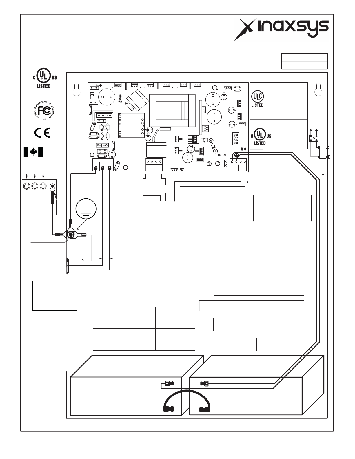
1 Mount the power supply in the desired location using the 4 mounting holes.
NOTE: For use in Indoor Protected Area with Controlled Environment only.
Do not Install Power Supply on Exterior Doors.
2 With the Mains power disconnected, connect the leads to the AC Input Terminal
Block, respecting the wiring phase and polarity :
Ground/Earth=Green/Yellow, Neutral = Blue (White), Live =Black (Brown). This
equipment must be connected to the 120-240 Volt Mains via a readily dedicated accessible
external disconnect device with maximum 15 Amp branch protection. Select the operating
3Do not connect the battery at this time.
4 Switch ON the AC. Green LED will come ON indicating AC is present and the AC
Fault Relay will be energized “ON” (closed). When the AC is off the AC Fault Relay
will drop open within 60 seconds (Factory set) activating the CMOS output
contact “AC Fail”. Connect this output to relevant monitoring devices.
5 Verify the DC output voltage is correct = 13.20VDC or 26.40VDC max. Blue DC LED
will be ON to indicate DC output is OK.
6 Yellow LED will be on and the BAT FAULT CMOS relay open indicating the Battery is
not present or connected with reversed polarity.
.
7 Connect the Battery or Batteries respecting the polarity. Battery shall not be connected
if AC is not present first.
8 If the battery is connected with the correct polarities the Yellow LED will turn OFF
(See Fault Conditions and Indications Table). Within one minute the Battery Fault Relay
will restore and the Yellow LED will flash once every 2 seconds.
9 If the battery is connected reverse polarity, the Yellow LED will be ON. (See the Table Fault).
The CMOS relay will open indicating Battery Fault. Connect this output to relevant monitoring
Installation Instructions
This power supply should be installed in compliance with National Electrical Code,
NFPA70 as well NFPA72 National Fire Alarm Code, CSA C22.1, Safety Standard
for Electrical Installations, Canadian Electrical Code, Part I, CAN/ULC-S524,
and all applicable Local Codes. Installation to be performed by suitably qualified
personnel. The power supply shall not be installed in the fail secure mode unless
permitted by the local authority having jurisdiction, and shall not interfere with the
operation of Listed panic hardware.
SW1 ON=12VDC, SW1 OFF=24VDC.
5
output DC voltage 12/24 with the jumper SW1.
devices.
10 Connect the devices to be powered to the output terminals marked “Vo- Vo+”.
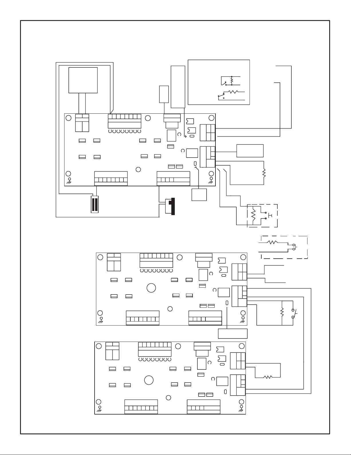
11 See below for installation of PD4ECB, PD8ECB, MOM8ECB and ACM4ECB
need 2 EOLR Resistors(2K2) provided. See Fig 1 & Fig 2.
12 If Tamper Switch is required use part # TSW1-02 or TWS2-02, see Fig 3.
13 Use 2K2 EOLR (end of line resistor) Part #EORL-PWX2K2
14 Connect the fault relays to FACP or ACP for trouble indication.
15 Secure the enclosure with the screw or with the Key Lock if provided.

Description:
The PD4ECB and the PD8ECB are distribution boards used for Fire Alarm, Bulglary,
Access Control and Egress Doors installation. The PD4ECB and PD8ECB board
have 4 and 8 outputs each rated max. 2.0Amp(max. total current 4 Amp), each with
Installation:
Connect the devices to be powered to the output terminals marked “ - DC +“ 1 to 4 or 1 to 8
of the PD4ECB and PD8ECB board. Red Led indicates output is live. Red Led OFF
indicates output is disabled due to overload or short, therefore the DC fail relay will open.
To reset the output, remove the Load or the Short and investigate the cause of
the trouble. Secure the enclosure with the screw and/or with the Key Lock if provided.
CMOS relay rating: 30Vdc, 60mA. 16ohms contact resistence.
The MOM8ECB is a distribution controller to be used with Access Control System,and Egress
Doors, It provides 12/24 vdc through 8 electronic over-current protected outputs, each rated
max. 2 amp(max. total current = 4 amp), each with electronic overcurrent. The 8 outputs will switch
ON or OFF security devices such as Magnetic Locks, Door Strikes, etc. It is to be connected
to FACP or ACP via a NO or NC configurable contact input with EOLR 2.2kohm.
(Part #EORL-PWX2K2) Also it has another input for Reversed Polarity triggering for older
version of Fire Alarm Control Panel. The MOM8ECB has 2 status relay output, one with
Dry Contact “Form C” to indicate output status and One Dry Contact “Form C” to indicate
DC Failure on any of the 8 outputs.
1. Output Connections
There are 8 selectable outputs suitable for FAIL Safe config and FAIL SECURE config.
1) For Fail Safe operation connect the device positive to DC STANDBY OUPUT (+)
on the MOM8ECB. DC power is present in normal condition and will switch OFF
when the FACP/ACP or Rev. Pol input is triggered. Fail Safe operation devices such
as Magnetic Lock should be connected to this output as show on Fig. 1.
2) For Fail Secure operation connect device positive to DC ALARM OUTPUT (+) on the
MOM8ECB. DC power is not present in normal condition and will switch ON when
the FACP/ACP input is triggered. Fail Secure Operation Devices such as Door Strikes
should be connected to this output.
6
Description:
Installation:
3) In either configuration connect the negative of the device to the NEGATIVE terminal CN8
PD4ECB, PD8ECB
MOM8ECB
electronic overcurrent protection set at 2.5 Amp.

2. Fire Alarm and Access Control interface connection
Normally Open (NO), Normally Closed (NC) input or Polarity Reverse (Rev. Volt.)
input are available to trigger the MOM8ECB operation. Connect the positive (+)
and Negative (-) from the FACP/ACP to the REV. VOLT terminals observing
the polarity,(polarity is referenced in alarm condition) or connect the NO or
NC from the FACP/ACP output to the “Fire Trigger Terminals”. Install a 2K2 Ohms (EOL)
PWX2K2 resistor at the FACP/ACP as show in Fig 1. Note: No ELOR on Rev. Pol.
3. Engineering RESET/REX Input
4. Relay Output
CD(ehtesuaclliwstuptuo8ehtfoeromroenotaliaftuptuoCD:liaFCD)a FAIL)
Trouble relay to open (De-energize). Connect this output to monitoring device. (28Vdc,
: :tuptuOsutatS)b FACP or ACP or Rev. Pol input will cause the dry contact Relay
“Form C” to open (de-energize). Connect this output to monitoring device. (28Vdc, 300mA)
5. Cascade Connection
Two(2) or more MOM8ECB units(maximum 20) can be connected together as follow:
Connect the status output relay Cand NC terminals from the 1st unit to the REMOTE
RESET INPUT of the 2nd unit(not polarity sensitive) and remove the JR of the 1st unit.
Install EOLR(2K2) on 2nd unit Fire Trigger terminal. If If a 3rd unit needs to connected
NOTE: If Latch Mode is used, only JL jumper on the first unit must be removed.
Engineering Reset will be performed from the 1st unit.
LD1 to LD8 RED LED when ON indicates that the output is ON (enable).
When OFF, the output is OFF, NO DC present (disable). The cause could be
Overload or short on the output. Note: all 8 outputs are current limited set at
2.5Amp, rated max 2.0Amp. LDF Fire Green Led is normally OFF. It will switch on
upon receiving an Input from the FACP/ACP. This led will stay ON following the
status of the FACP/ACP input. IF JL was removed this LED will stay ON until the manual
RESET circuit resets.
7
JL ON will cause the unit to follow the FIRE/ACP TRIGGER.
This option is avaliable when the Jumper JL is removed(JL OFF). This will cause the
MOM8ECB to latch upon receiving alarm from the FACP or ACP with this option in
place. When the FIRE/ACP TRIGGER resets, MOM8ECB will only reset by activating
the RESET/REX input.
Install the 2K2 EOLR
6. MOM8ECB LED Indication:
(end of line resistor) #EORL-PWX2K2 at the key Switch or Push Button to perform
This Operation.
300mA)
The
the JR of the 2nd unit must be removed and so on for any additional unit. Ref to Fig.1.

ACM4ECB
DESCRIPTION:
The ACM4ECB is a distribution controller to be used with card Access Control, Egress Doors.
It provides 12/24Vdc through 4 outputs rated 2.0A(max. 4A total) each with electronic over-current
protection set at 2.5A. The 4 outputs will switch ON or OFF security devices such as Magnetic Locks,
Door Strikes, etc. It is connected to FACP or ACP via a NO or NC configurable contact input
using 2K2 EOLR(Part #EORL-PWX2K2). Also it has input for Reversed Polarity triggering.
The ACM4ECB has 2 relay outputs, one Dry Contact “Form C” to indicate output status, and one
Dry Contact “Form C” to indicate DC failure on any of the 4 outputs, due to overcurrent or short.
Installation:
There are 4 selectable outputs suitable for FAIL Safe config and Fail Secure config.
For Fail Safe Operation connect the positive (+) lead of the device to normally
Closed (NC) and the negative lead to COM ”Neg”, connector CN1 to CN4. DC
power is present in normal condition and will switch OFF when FACP/ACP or
or Reverse Polarity input is triggered. Fail Safe operation devices such as,
Magnetic Lock should be connected to this output as show on Fig. 2.
1. Output Connections
2. Fire Alarm and Access Control Interface
Normally Open (NO), Normally Closed (NC) input or Polarity Reverse (Rev. Volt.) input
are available to trigger the ACM4ECB operation. Connect the positive(+) and Negative(-)
from the FACP or ACP to the REV. VOLT terminals observing the polarity,
(polarity is referenced in alarm condition) or connect the NO or NC from the FACP
or ACP output to the “Fire Trigger “terminals. Install PWX2K2 2k2 (EOLR) resistor
at the FACP or ACP as show in Fig. 1. Note: No ELOR on Rev. Pol.
3. Engineering RESET/REX Input
a)
b)
8
For Fail Secure operation connect device positive(+) lead to Normally Open (NO)
DC power is not present in normal condition and will switch ON when the
FACP or ACP or Reverse Polarity input is triggered. Fail Secure operation
devices such as Door Strikes should be connected to this output.
JL ON will cause the unit to follow the FIRE/ACP TIGGER.
(EOLR) resistor at the Key Switch or Push Button to perform this operation.
This option is avaliable when the Jumper JL is removed(JL OFF). This will cause
the ACM4ECB to latch opon receiving Input from the FACP or ACP with this option
in place and when the FIRE/ACP TRIGGER resets, ACM4ECB will only reset by
activating the RESET/REX input.
Install PWX2K2 2.2K

9
4. Relay Output
a) DC Fail: When one or more of the 4 outputs fail due to over current or short circuit
condition, the DC fail Relay will open. Connect this output to monitoring device. (28Vdc,
300mA)
b) Status Output:: When the FACP or ACP input activates this will cause the dry contact
Form “C” to change state (de-energize). Connect this output to monitoring device.
5. Cascade Connection
Two(2) or more ACM4ECB units can be connected together as follow: Connect the Status
Output relay Cand NC terminals from the 1st unit to the REMOTE RESET/REX INPUT
of the 2nd unit(not polarity sensitive) and remove the JR of the 1st unit. Install EOLR(2K2) on
2nd unit Fire Trigger terminal. If 3rd unit is connected, the JR of the 2nd unit must be
NOTE: If Latch Mode is used, only JL jumper on the first unit must be removed. Engineering
Reset will be performed from the 1st unit.
6. ACM4ECB LED INDICATION
L1 to L4 are the Output RED Led, when ON indicates DC is present (enable), and
the Output relays are energized.
When OFF, Relay is de-energized and the output is OFF, NO DC present (disable).
Current limited set @ 2.5Amp, rated at max 2.0Amp.
L9 Green Led is normally OFF. It will switch on upon receiving an alarm from the FACP/ACP.
This LED will stay ON following the status of the FACP/ACP input. If JL was removed this
LED will stay ON until the manual RESET circuit resets.
7. Access Control Panel (ACP)Trigger input.
8. FACP/ACP Input Programming
Selectable Output to be Irrelevant on Fire Activation
To have the output relay activation follow the FACP or ACP input place the DIP switch
corresponding to desired relay to the “OFF” position. In the “ON position, the correspondent
output relay will not be effected by the FACP,ACP or Rev. Pol input.
9. Isolated Output Configuration
If any of the outputs requires to be Isolated DRY CONTACT, remove the respective Jumper
J1 through J4 to achieve this configuration, Form “C”,(C NO NC) available to connectors CN1
through CN4. This connection is now isolated from the internal power source.
Relay Rating: 28Vdc, 2A. PF 0.6
Relay
(28Vdc, 300mA)
removed, and so on for any additional unit. Ref to Fig.1.
LD1 to LD4 Yellow LED indication denotes overload or short on the output. The outputs are
There are 4 inputs, CN10 through CN13 each with two terminals, IN and GND. Activation
of the inputs is achieved by shorting IN and GND terminals of the respective inputs.
-
-
+
+
battery jumper
BATTERY 1
BATTERY 2
AMP BATTERY
AMP BATTERY
BATTERY CONNECTION NON POWER LIMITED
DX400
TO MONITOR POINT
RT2
L4
C5
C4
CN3
CN2
CN6CN7
D6
D16
Q12
D17
C11
C47
IC9
T1
L8
Q12
Q11
C66
C37
LED-B
D25
C54 Q18
IC13
IC12
C6
L6
L5
C8
D5A
D5
Q3A
Q3
D3
L9
C7
L1
L2
CY2
CY3
K1
CY6
L3
Q1
R1
NTC
OUTPUT
D.C.
BATT.
TEMP
FAIL
BATTERY
+
+
GND NL
BATTERY
- + - +
SW1
12/24
PANEL LED LED-Y LED-R
LB
LED9
T4A/ 250Vac
NTC
LED-G
CX2
DB1
Q30
CX1
L1A
MOV
F1
PROGRAM
VR1
Q1
D2
C3
AC
FAIL
C2
C1
CY5
SOFTWARE VER 1.8
DX-200W-PCB
TAMPER
SWITCH
N/C TAMPER OUT
CONNECTOR
HPVM3 ASSY
TOP LEVER
DX400UL
CABINET GROUND
AWG 14
EARTH
GROUND
STUD
ULC-S533, UL 294
COMMERCIAL FIRE
BURGLAR ALARM
ACCESS CONTROL
REGULATED POWER
SUPPLY CHARGER
FIRE ALARM AND SECURITY EQUIPMENT
21A6
SECURITY
SIGNALING
UL/ULC LISTED AS FOLLOWS:
UL2 94,CAN/ULC-60839-11-1,CAN/ULC-S533 FOR ACCESS CONTROL SYSTEM
REGULATED POWER SUPPLY CHARGER
UL864,CAN/ULC-S527 FOR COMMERCIAL FIRE
UL603, ULC-S318 FOR BURGLARY ALARM SYSTEM
10
NOTE: PLEASE REFER TO DX400UL INSTALLATION MANUAL, PART NO:PX4000 REV:01
For use in Indoor
Dry controlled
Environment
AC INPUT
120-240 VAC
50-60Hz 1.8A
G N L
G N L
Regulated 12/24 VDC 4.0Amp For wiring size use 22 to 14AWG
TESTED FOR:
ULC-S318, UL603
ULC-S527, UL 864
ULC-60839-11-1
KEEP POWER LIMITED WIRING FROM NON POWER LIMITED WIRING AT LEAST 0.25" INCH APART
FIRE PROTECTIVE SIGNALING
4 2 4
4
LOAD (A)
4
LOAD (A)
[V]
24V
12V
12AH BATTERY 17.2AH BATTERY
STANDBY OPERATION
[HOURS]
TIME
VOLTAGE
OUTPUT STANDBY OPERATION
[HOURS]
TIME
2
2
2
12 / 17.2
12 / 17.2
I.T.E. POWER SUPPLY
E220695
Battery capacity for loss of primary power
at least (see table below) hours for:
UL294, CAN/ULC-60839-11-1:
Grade 3"
STANDBY BATTERIES TIME/VOLTAGE CHARTS
OUTPUT
VOLTAGE
TIME
[HOURS]
STANDBY
(A)
ALARM
(A)
[MIN.] [MIN.] (A)
ALARM
(A)
STANDBY
17.2AH BATTERY12AH BATTERY
Calculation with 20% safety margin
4.0
150mA 3.0 4.0
150mA 3.0
12
24
FIRE ALARM & BURGLARY APPLICATION ULC-S318
PART NO:PX4001 REV:01
12 VOLT 12 VOLT
150mA 30 4.0 4.0
250mA 3.0 4.0
250mA 3.0
12
24
BURGLAR APPLICATIONS TO UL603
4
150mA 30 4.0
4
DATE OF MFG:
AWG14
LED’S PANEL
BAT
AC
GRN
DC
DOOR
PANEL GROUND STUD
YEL
BLU
For fire applications in US, all interconnecting wiring
are Class E, unsupervised. For fire applications in
Canada, interconnecting wiring shall be supervised
by interconnected fire alarm equipment or be limited
to 18 m run in a metallic conduit
SPECIAL LOCKING
ARRANGMENT
24
24
CSA C22.1, Safety Standard
for Electrical Installations,
Canadian Electrical Code,
Part I, CAN/ULC-S524
Code and all applicable codes.
as NFPA72 Nation a Fire Alarm
Electrical Code NFPA70, as well
in compliance with the National
This Product must be installed
REG# T1880475-02
REG# T1880475-01
Canada
Industry
REG# T1880475-03

-
-
+
+
battery jumper
BATTERY 1
BATTERY 2
AMP BATTERY
AMP BATTERY
BATTERY CONNECTION NON POWER LIMITED
DX400
TO MONITOR POINT
RT2
L4
C5
C4
CN3
CN2
CN6 CN7
D6
D16
Q12
D17
C11
C47
IC9
T1
L8
Q12
Q11
C66
C37
LED-B
D25
C54 Q18
IC13
IC12
C6
L6
L5
C8
D5A
D5
Q3A
Q3
D3
L9
C7
L1
L2
CY2
CY3
K1
CY6
L3
Q1
R1
NTC
OUTPUT
D.C.
BATT.
TEMP
FAIL
BATTERY
+
+
GND NL
BATTERY
- + - +
SW1
12/24
PANEL LED LED-Y LED-R
LB
LED9
T4A/250Vac
NTC
LED-G
CX2
DB1
Q30
CX1
L1A
MOV
F1
PROGRAM
VR1
Q1
D2
C3
AC
FAIL
C2
C1
CY5
EACH OUTPUT RATED AT 2.0AMP, Maximum 3 Amp Total
OUT4OUT3
OUT2
OUT1 + -- -+
+
-
+
MADE IN CANADA
PD4ECB
POWER-PLEX
VR1
+
-CNC
DC TRBL
DC INPUT
EARTH
GROUND
EARTH
GROUND
CN3
CN2
QQ1
QQ2
QQ3
QQ4
L1 L2 L3 L4
CN1
DX-200W-PCB
TAMPER
SWITCH
N/C TAMPER OUT
CONNECTOR
HPVM3 ASSY
TOP LEVER
DATE OF MFG:
DX400ULPD4ECB
CABINET GROUND
AWG 14
EARTH
GROUND
STUD
11
G N L
AC INPUT
120-240 VAC
50-60Hz 1.8A
G N L
For use in Indoor
Dry controlled
Environment
UL/ULC LISTED AS FOLLOWS:
REGULATED POWER SUPPLY CHARGER
NOTE: PLEASE REFER TO DX400UL INSTALLATION MANUAL, PART NO:PX4000 REV:01
FIRE PROTECTIVE SIGNALING
4 2 4
4
LOAD (A)
4
LOAD (A)
[V]
24V
12V
12AH BATTERY 17.2AH BATTERY
STANDBY OPERATION
[HOURS]
TIME
VOLTAGE
OUTPUT STANDBY OPERATION
[HOURS]
TIME
2
2
2
KEEP POWER LIMITED WIRING FROM NON POWER LIMITED WIRING AT LEAST 0.25" INCH APART
COMMERCIAL FIRE
BURGLAR ALARM
ACCESS CONTROL
REGULATED POWER
SUPPLY CHARGER
FIRE ALARM AND SECURITY EQUIPMENT
(NEC AND CEC CLASS 2 CIRCUIT, 60950 LPS CIRCUIT)
ULC-S533, UL 294
21A6
TESTED FOR:
ULC-S318, UL603
ULC-S527, UL 864
ULC-60839-11-1
Regulated 12/24 VDC 4.0Amp
UL2 94,CAN/ULC-60839-11-1,CAN/ULC-S533 FOR ACCESS CONTROL SYSTEM
UL864,CAN/ULC-S527 FOR COMMERCIAL FIRE
UL603, ULC-S318 FOR BURGLARY ALARM SYSTEM
12 / 17.2 12 / 17.2
I.T.E. POWER SUPPLY
E220695
SECURITY
SIGNALING
Battery capacity for loss of primary power
at least (see table below) hours for:
OUTPUT
VOLTAGE
TIME
[HOURS]
STANDBY
(A)
ALARM
(A)
[MIN.] [MIN.] (A)
ALARM
(A)
STANDBY
17.2AH BATTERY12AH BATTERY
4.0
150mA 30 4.0
150mA 30
12
24
12 VOLT 12 VOLT
PART NO:PX4002 REV:01
150mA 30 4.0 4.0
250mA 30 4.0
250mA 30
12
24
BURGLAR APPLICATIONS TO UL603
4
150mA 30 4.0
4
AWG14
LED’S PANEL
BAT
AC
GRN
DC
DOOR
PANEL GROUND STUD
YEL
BLU
For wiring size use 22 to 14AWG
For fire applications in US, all interconnecting wiring
are Class E, unsupervised. For fire applications in
Canada, interconnecting wiring shall be supervised
by interconnected fire alarm equipment or be limited
to 18 m run in a metallic conduit
FIRE ALARM & BURGLARY APPLICATION ULC-S318
UL294, CAN/ULC-60839-11-1:
Grade 3"
SPECIAL LOCKING
ARRANGMENT
24
24
STANDBY BATTERIES TIME/VOLTAGE CHARTS
Calculation with 20% safety margin
CSA C22.1, Safety Standard
for Electrical Installations,
Canadian Electrical Code,
Part I, CAN/ULC-S524
Code and all applicable codes.
as NFPA72 Nation a Fire Alarm
Electrical Code NFPA70, as well
in compliance with the National
This Product must be installed
REG# T1880475-02
REG# T1880475-01
Canada
Industry
REG# T1880475-03

12 VOLT12 VOLT
-
-
+
+
battery jumper
BATTERY 1
BATTERY 2
12 / 17.2 AMP BATTERY
12 / 17.2 AMP BATTERY
BATTERY CONNECTION NON POWER LIMITED
TO MONITOR POINT
RT2
L4
C5
C4
CN3
CN2
CN6 CN7
D6
D16
Q12
D17
C11
C47
IC9
T1
L8
Q12
Q11
C66
C37
LED-B
D25
C54 Q18
IC13
IC12
C6
L6
L5
C8
D5A
D5
Q3A
Q3
D3
L9
C7
L1
L2
CY2
CY3
K1
CY6
L3
Q1
R1
NTC
OUTPUT
D.C.
BATT.
TEMP
FAIL
BATTERY
+
+
GND NL
BATTERY
- + - +
SW1
12/24
PANEL LED LED-Y LED-R
LB
LED9
T4A/250Vac
NTC
LED-G
CX2
DB1
Q30
CX1
L1A
MOV
F1
PROGRAM
VR1
Q1
D2
C3
AC
FAIL
C2
C1
CY5
EACH OUTPUT RATED AT 2.0AMP, Maximum 4 Amp Total
+ -- -+
+
-
+
MADE IN CANADA
PD4ECB
+
-CNC
DC TRBL
DC INPUT
EARTH
GROUND
EARTH
GROUND +-++ -+ --
VR1
QQ6
QQ5
OUT1 OUT2 OUT3 OUT4 OUT5 OUT6 OUT7 OUT8
QQ1
QQ2
QQ3
QQ4
QQ7
QQ8
VR2
L1 L2 L3 L4 L5 L6 L7 L8
CN1
CN2
CN4
CN3
DX400
STUD
GROUND
EARTH
AWG 14
CABINET GROUND
DX-200W-PCB
TAMPER
SWITCH
N/C TAMPER OUT
CONNECTOR
HPVM3 ASSY
TOP LEVER
DATE OF MFG:
DX400ULPD8ECB
12
AC INPUT
120-240 VAC
50-60Hz 1.8A
G N L
(NEC AND CEC CLASS 2 CIRCUIT,
60950 LPS CIRCUIT
)
For use in Indoor
Dry controlled
Environment
G N L
UL/ULC LISTED AS FOLLOWS:
REGULATED POWER SUPPLY CHARGER
NOTE: PLEASE REFER TO DX400UL INSTALLATION MANUAL, PART NO:PX4000 REV:01
FIRE PROTECTIVE SIGNALING
KEEP POWER LIMITED WIRING FROM NON POWER LIMITED WIRING AT LEAST 0.25" INCH APART
4 2 4
4
LOAD (A)
4
LOAD (A)
[V]
24V
12V
12AH BATTERY 17.2AH BATTERY
STANDBY OPERATION
[HOURS]
TIME
VOLTAGE
OUTPUT STANDBY OPERATION
[HOURS]
TIME
2
2
2
COMMERCIAL FIRE
BURGLAR ALARM
ACCESS CONTROL
REGULATED POWER
SUPPLY CHARGER
FIRE ALARM AND SECURITY EQUIPMENT
UL2 94,CAN/ULC-60839-11-1,CAN/ULC-S533 FOR ACCESS CONTROL SYSTEM
UL864,CAN/ULC-S527 FOR COMMERCIAL FIRE
UL603, ULC-S318 FOR BURGLARY ALARM SYSTEM
ULC-S533, UL 294
21A6
TESTED FOR:
ULC-S318, UL603
ULC-S527, UL 864
ULC-60839-11-1
Regulated 12/24 VDC 4.0Amp
SECURITY
SIGNALING
I.T.E. POWER SUPPLY
E220695
Battery capacity for loss of primary power
at least (see table below) hours for:
OUTPUT
VOLTAGE
TIME
[HOURS]
STANDBY
(A)
ALARM
(A)
[MIN.] [MIN.] (A)
ALARM
(A)
STANDBY
17.2AH BATTERY12AH BATTERY
4.0
150mA 3.0 4.0
150mA 3.0
12
24
PART NO:PX4003 REV:01
150mA 30 4.0 4.0
250mA 3.0 4.0
250mA 3.0
12
24
BURGLAR APPLICATIONS TO UL603
4
150mA 30 4.0
4
AWG14
LED’S PANEL
BAT
AC
GRN
DC
DOOR
PANEL GROUND STUD
YEL
BLU
For wiring size use 22 to 14AWG
FIRE ALARM & BURGLARY APPLICATION ULC-S318
For fire applications in US, all interconnecting wiring
are Class E, unsupervised. For fire applications in
Canada, interconnecting wiring shall be supervised
by interconnected fire alarm equipment or be limited
to 18 m run in a metallic conduit
UL294, CAN/ULC-60839-11-1:
Grade 3"
SPECIAL LOCKING
ARRANGMENT
24
24
STANDBY BATTERIES TIME/VOLTAGE CHARTS
Calculation with 20% safety margin
CSA C22.1, Safety Standard
for Electrical Installations,
Canadian Electrical Code,
Part I, CAN/ULC-S524
Code and all applicable codes.
as NFPA72 Nation a Fire Alarm
Electrical Code NFPA70, as well
in compliance with the National
This Product must be installed
REG# T1880475-02
REG# T1880475-01
Canada
Industry
REG# T1880475-03

BATTERY CONNECTION NON POWER LIMITED
AMP BATTERY
BATTERY 2
BATTERY 1
battery jumper
+
+
-
-
CY5
C1
C2
FAIL
AC
C3
D2
Q1
VR1
PROGRAM
F1
MOV
L1A
CX1
Q30
DB1
CX2
LED-G
NTC T4A/250Vac
LED9
LB
LED-R
LED-Y
PANEL LED
12/24
SW1
- +
- +
BATTERY
L
N
GND
+
+
BATTERY
FAIL
TEMP
BATT. D.C.
OUTPUT
NTC
R1 Q1
L3
CY6
K1
CY3
CY2
L2
L1
C7
L9
D3 Q3 Q3A D5 D5A
C8
L5
L6
C6
IC12
IC13
Q18
C54
D25
LED-B
C37
C66
Q11
Q12
L8
T1 IC9
C47
C11
D17
Q12
D16
D6
CN7
CN6
CN2
CN3
C4
C5
L4
RT2
TO MONITOR POINT
CN1
QQ1 QQ2
QQ5 QQ6
QQ3 QQ4
QQ7 QQ8
QQ9 QQ10
REG1
JL
TO LATCH
FACP
FIRE
LED
CASCADE
CN3
CN2
CN8
CN13 LDF
LD1 LD2 LD3 LD4 LD5 LD6 LD7 LD8
GROUND
EARTH
GROUND
EARTH
MADE IN CANADA
K2
k1
- N E G A T I V E -
8N
7N
6N
5N
4N
3N
2N
1N
C NO NC
DC TROBLE DC INPUT
+
-
FIRE
TRIGGER REV.POL
-+
RESET
REMOTE
CNO NC
STATUS
1P 2P 3P 4P 5P 6P 7P 8P
POS + DC STANDBY OUTPUTS
7P
6P
5P
4P
3P
2P
1P 8P
POS + DC ALARM OUTPUTS
MOM8ECB
ALARM OUTPUTS
STANDBY OUTPUTS EOL RESISTOR
PWX2K2
KEY SWICTH
EOLR
2K2
FROM FACP/ACP
INSTALL 2K2 EOLR AT FACP/ACP
STRIKE
ELECTRIC DOOR
MAGNETIC
LOCK
STUD
GROUND
EARTH
AWG 14
CABINET GROUND
DX400ULMOM8ECB
DATE OF MFG:
TOP LEVER
HPVM3 ASSY
CONNECTOR
N/C TAMPER OUT
SWITCH
TAMPER
DX-200W-PCB
DX400
AC INPUT
120-240 VAC
50-60Hz 1.8A
G N L
NOTE: PLEASE REFER TO DX400UL INSTALLATION MANUAL, PART NO:PX4000 REV:01
UL/ ULC LISTED AS FOLLOWS:
U L2 9 4, C A N / ULC-60839-11-1,C A N / ULC-S533
REGULATED POWER SUPPLY CHARGER
13
44
4
LOAD (A)
4
LOAD (A)
[V]
24V
12V
12AH BATTERY 17.2AH BATTERY
STANDBY OPERATION
[HOURS]
TIME
VOLTAGE
OUTPUT STANDBY OPERATION
[HOURS]
TIME
2
2
2
(NEC AND CEC CLASS 2 CIRCUIT, 60950 LPS CIRCUIT)
FAIL SAFE CONFIG
FAIL SECURE CONFIGURATION
POWER SUPPLY FOR ACCESS CONTROL SYSTEM
2K2
EOLR
KEY SWITCH
N/C CONFIG.
EOLR
2K2
FACP/ACP
C
NO
NC
N/O CONFIG.
EOLR
2K2
NC
NO
C
FACP/ACP
N/C CONFIG.
G N L
FOR WIRING SIZE USE 22 TO 14AWG
For use in Indoor
Dry controlled
Environment
and all applicable codes. CSA C22.1,
Safety Standard for Electrical Installations,
Canadian Electrical Code.
with National Electrical CodeNFPA70,
This Product must be installed in compliance
KEEP POWER LIMITED WIRING FROM NON POWER LIMITED WIRING AT LEAST 0.25" INCH APART
ACCESS CONTROL POWER
SUPPLY CHARGER
SECURITY EQUIPMENT
12/24 VDC 4.0Amp
Maximum wiring resistence 200 Ohm
Maximum wiring resistence 200 Ohm
N/O CONFIG
To Trouble Monitoring
ULC-S533, UL 294
TESTED FOR:
ULC-60839-11-1
12 / 17.2 AMP BATTERY12 / 17.2
Trigger Input
Trigger Input
SECURITY
21A6
I.T.E. POWER SUPPLY
E220695
Battery capacity for loss of primary power
at least (see table below) hours for:
PART NO:PX4004 REV:01
12 VOLT 12 VOLT
2
AWG14
LED’S PANEL
BAT
AC
GRN
DC
DOOR
PANEL GROUND STUD
YEL
BLU
SPECIAL LOCKING
ARRANGMENT
UL294, CAN/ULC-60839-11-1:
Grade 3"
REG# T1880468-02
REG# T1880468-01
Canada
Industry
REG# T1880468-03
FOR WIRING SIZE USE 22 TO 14AWG
(NEC and CEC CLASS 2 CIRCUIT)
FAIL SECURE CONFIGURATION
FAIL SAFE CONFIGURATION
ALARM OUTPUT
STANDBY OUTPUTS
USE ONLY UL LISTED EOL RESISTOR
USE ONLY UL LISTED EOL RESISTOR
UNTIL REMOTE ACTIVATE
TO LACHT OUPUT
REMOVE JL
REMOVE JR
EOLR
2K2
2K2
EOLR
TO FACP/ACP
2
1
12/24 VDC
LD8LD7LD6LD5LD4LD3LD2
LD1
GREEN
LDF
POWER FAIL
LATCH
JL
CASCADE
JR
QQ10QQ9
QQ8
QQ7
REG1
QQ4
QQ3
QQ6
QQ5
QQ2
QQ1
GROUND
EARTH GROUND
EARTH
MADE IN CANADA
R32
K2
K1
- N E G A T I V E -
8N
7N
6N
5N
4N
3N
2N
1N
CNO NC
DC TROBLE DC INPUT
+
-
FIRE
TRIGGER REV VOLT
-+
RESET CNO NC
STATUS
1P 2P 3P 4P 5P 6P 7P 8P
POS + DC STANDBY OUTPUTS
7P
6P
5P
4P
3P
2P
1P 8P
POS + DC ALARM OUTPUTS
MOM8ECB
12/24 VDC
LD8LD7LD6LD5LD4LD3LD2
LD1
GREEN
LDF
POWER FAIL
LATCH
JL
CASCADE
JR
QQ10QQ9
QQ8
QQ7
REG1
QQ4
QQ3
QQ6
QQ5
QQ2
QQ1
GROUND
EARTH GROUND
EARTH
MADE IN CANADA
R31
K2
K1
- N E G A T I V E -
8N
7N
6N
5N
4N
3N
2N
1N
CNO NC
DC TROBLE DC INPUT
+
-
FIRE
TRIGGER REV VOLT
-+
CNO NC
STATUS
1P 2P 3P 4P 5P 6P 7P 8P
POS + DC STANDBY OUTPUTS
7P
6P
5P
4P
3P
2P
1P 8P
POS + DC ALARM OUTPUTS
MOM8ECB
FIRE ALARM MARSHAL OPTION
TO REMOTE RESET
N/O CONFIGURATION
EOLR
2K2
OUTPUT
STATUS
POLARITY TERMINAL
TO REVERSED
N/C CONFIGURATION
N/0 CONFIGURATION
2K2
_
+
REV POL.
CONTROL PANEL
ACP or FACP
TERMINAL
TO FACP/ACP INPUT
MOM8ECBUL
TO ANOTHER
TO CONNECT
REMOVE JR
TROUBLE
POWER FAIL
12/24VDC
SUPPLY
POWER
DX400
MOM8ECB
POS + DC ALARM OUTPUTS
8P
1P 2P 3P 4P 5P 6P 7P
POS + DC STANDBY OUTPUTS
8P7P
6P
5P
4P
3P
2P
1P
STATUS
NCNO
C
RESET
REMOTE
+
-
REV VOLTTRIGGER
FIRE
-+
DC INPUT
DC TROBLE
NCNO
C
1N
2N
B¶?
5N
6N
7N
8N
- N E G A T I V E -
K1
K2
R30
MADE IN CANADA
POWER-PLEX
EARTH
GROUND
EARTH
GROUND
QQ1 QQ2
QQ5 QQ6
QQ3 QQ4 REG1
QQ7 QQ8
QQ9 QQ10
JR
CASCADE
JL
LATCH
POWER FAIL
LDF
GREEN
LD1 LD2 LD3 LD4 LD5 LD6 LD7 LD8
12/24 VDC
USE UL LISTED EOLR
RESET CAN ONLY PERFORMED
FROM UNIT 1
KEY SWITCH
LOCK
MAGNETIC
STRIKE
ELCTRIC DOOR
2K2
EOLR
KEY SWICTH
PART NO: PX4005 REV:01
FIG.1
2 OR MORE DX400ULMOM8ECB CONNECTED IN CASCADE
TYPICAL APPLICATION WIRING DIAGRAM
14
RESET
REMOTE
KEEP POWER LIMITED WIRING FROM NON POWER LIMITED WIRING AT LEAST 0.25" INCH APART
2K2
EOLR
KEY SWITCH
N/C CONFIG.
1 INPUT ONLY
REV POL or FACP/ACP
INPUT CAN BE USED.
2K2
USE ONLY UL LISTED EOL RESISTOR

-
-
+
+
BATTERY 2
BATTERY CONNECTION NON POWER LIMITED
PWX2K2 EOL RESISTOR
QQ4
QQ3
QQ2
QQ1
SWITCH
DIP
JJ2
JJ1
&
REMOTE
RESET/REX
R/POL
-
+
FIRE TRIG.
OFF 41 2 3
ON
SWITCH RELEVANT
FOR FIRE CONTROL
NO
NC
C
C
NO NC
NO
CNC
+
+-
-
ACM4ECB
FIRE
INPUT
EARTH
GND
POWER CONTROL STATUS
C NO NC
DC TRBL
POSITION TO OFF
C
NO NC NC
NO
CC
NO NC
C
NO NC
OUTPUT 1 OUTPUT 2 OUTPUT 3 OUTPUT 4
NC C NO COM (Neg) NC C NO COM (Neg) NC C NO COM (Neg) NC C NO COM (Neg)
IN GND IN GND IN GND IN GND
INPUTINPUT
INPUT
INPUT
1
2
3
4
L1 J1 L2 J2 L3 J3 L4 J4
D17
C10
C13
JR
CASCADE
L9
JL
LATCH
MODE
K6
K9
K1 K2 K3 K4
LY1 LY2 LY3 LY4
EARTH
GND
TO MONITOR POINT
RT2
L4
C5
C4
CN3
CN2
CN6 CN7
D6
D16
Q12
D17
C11
C47
IC9
T1
L8
Q12
Q11
C66
C37
LED-B
D25
C54 Q18
IC13
IC12
C6
L6
L5
C8
D5A
D5
Q3A
Q3
D3
L9
C7
L1
L2
CY2
CY3
K1
CY6
L3
Q1
R1
NTC
OUTPUT
D.C.
BATT.
TEMP
FAIL
BATTERY
+
+
GND NL
BATTERY
- +
- +
SW1
12/24
PANEL LED LED-Y LED-R
LB
LED9
T4A/250Vac
NTC
LED-G
CX2
DB1
Q30
CX1
L1A
MOV
F1
PROGRAM
VR1
Q1
D2
C3
AC
FAIL
C2
C1
CY5
DX400
ELECTRIC DOOR STRIKE
INSTALL 2K2 EOLR AT FACP
ACP/FACP
2K2
EOLR
KEY SWICTH
MAGNETIC
LOCK
PWX2K2
EOL RESISTOR
DX-200W-PCB
TAMPER
SWITCH
N/C TAMPER OUT
CONNECTOR
HPVM3 ASSY
TOP LEVER
DATE OF MFG
DX400ULACM4ECB
CABINET GROUND
AWG 14
EARTH
GROUND
STUD
15
AC INPUT
120-240 VAC
50-60Hz 1.8A
G N L
NOTE: PLEASE REFER TO DX400UL INSTALLATION MANUAL, PART NO:PX4000 REV:01
UL/ ULC LISTED AS FOLLOWS:
U L2 9 4, C A N / ULC60839-11-1,C A N / ULC-S533
REGULATED POWER SUPPLY CHARGER
POWER SUPPLY FOR ACCESS CONTROL SYSTEM
For use in Indoor
Dry controlled
Environment
G N L
(NEC AND CEC CLASS 2 CIRCUIT, 60950 LPS CIRCUIT)
4 2 4
4
LOAD (A)
4
LOAD (A)
[V]
24V
12V
12AH BATTERY 17.2AH BATTERY
STANDBY OPERATION
[HOURS]
TIME
VOLTAGE
OUTPUT STANDBY OPERATION
[HOURS]
TIME
2
2
2
EOLR
2K2
FACP/ACP
C
NO
NC
N/O CONFIG.
EOLR
2K2
NC
NO
C
N/C CONFIG.
2K2
EOLR
KEY SWITCH
N/C CONFIG.
FACP/ACP
FAIL SAFE CONFIG FAIL SECURE CONFIGURATION
KEEP POWER LIMITED WIRING FROM NON POWER LIMITED WIRING AT LEAST 0.25" INCH APART
FOR WIRING SIZE USE 22 TO 14AWG
ACCESS CONTROL
POWER
SUPPLY CHARGER
12/24 VDC 4.0Amp
CN1 CN2 CN3 CN4
CN10 CN11
RESET
EACH OUTPUT RATED AT 2.0AMP, Maximum 4 Amp Total
AMP BATTERY12 / 17.2
AMP BATTERY12 / 17.2
ULC-S533, UL 294
21A6
TESTED FOR:
ULC-60839-11-1
SECURITY
SIGNALING
I.T.E. POWER SUPPLY
E220695
Battery capacity for loss of primary power
at least (see table below) hours for:
PART NO:PX4006 REV:01
SECURITY EQUIPMENT
12 VOLT 12 VOLT
battery jumper
BATTERY 1
AWG14
LED’S PANEL
TAB
CA
GRN
CD
DOOR
PANEL GROUND STUD
YEL
BLU
UL294, CAN/ULC-60839-11-1:
Grade 3"
SPECIAL LOCKING
ARRANGMENT
and all applicable codes. CSA C22.1,
Safety Standard for Electrical Installations,
Canadian Electrical Code.
with National Electrical CodeNFPA70,
This Product must be installed in compliance
REG# T1880471-02
REG# T1880471-01
Canada
Industry
REG# T1880471-03

FACP/ACP INPUT
TERMINAL
TO REVERSED
POLARITY TERMINAL
STATUS
OUTPUT
2K2
EOLR
N/O CONFIGURATION
TO REMOTE RESET
FIRE ALARM MARSHAL OPTION
REMOVE JL
TO LACHT OUPUT
UNTIL REMOTE ACTIVATE
GND
EARTH
LY4
LY3
LY2
LY1
K4
K3
K2
K1
K9
K6
MODE
LATCH
JL
L9
CASCADE
JR
C13
C10
D17
J4L4
J3L3
J2
L2
J1
L1
4321
INPUT INPUT INPUT INPUT
IN GND
IN GND
IN GND
IN GND
NC C NO COM
NC C NO COMNC C NO COMNC C NO COM
OUTPUT 4 (Neg)
OUTPUT 3 (Neg)OUTPUT 2 (Neg)OUTPUT 1 (Neg)
NC
NO
C
NC
NO
C
C
NO NCNC
NO
C
POSITION TO OFF
TRBL
NCNOC
STATUS
CONTROL
POWER
GND
EARTH
INPUT
FIRE
ACM4ECB
--
++NC
CNO
NCNO
C
C
NC
NO
FOR FIRE CONTROL
SWITCH RELEVANT
ON
1 2 3 4
OFF
FIRE TRIG. +
-
R/POL
RESET/REX
REMOTE
&
JJ1
JJ2
DIP
SWITCH
KEY PAD
C
NO
NC
ACCESS CONTROL
PANEL
RELAY OUTPUT
UL N/0 PUSH BUTTON
OUTPUT 1 AND 4 ARE DESABLE TO THE ACP/FACP
OUPUT 2 AND 3 ARE ENABLE TO ACP/FACP
POWER FAIL
OUTPUT FAIL
CONNECT TO
MONITORING
TO AUXLIARY UL LISTED
POWER SUPPLY
NOTE:
IN THIS CONFIGUARTION
J4 MUST BE REMOVED
FOR ISOLATED CONTACT
CONNECTED TO DX400
KEY SWICTH
EOLR
2K2
MAGNETIC
LOCK
ELCTRIC DOOR
STRIKE
MAGNETIC
LOCK
USE UL LISTED EOL RESISTOR
USE ONLY UL LISTED EOL RESISTOR
PART NO: PX4007 REV:01
FIG 2
TYPICAL APPLICATION WIRING DIAGRAM
2 OR MORE DX400ULACM4ECB CONNECTED IN CASCADE
SECURE SAFE
CONFIGURATION
16
FAIL SAFE
CONFIGURATION
1 2 3
4 5 6
7 8 9
* # 0
2
LY4
LY3
K4
K3
K9
K6
MODE
LATCH
JL
L9
CASCADE
JR
C13
C10
D17
J4L4
J3L3
J2
NC C NO COM
NC C NO COM
OUTPUT 4 (Neg)
OUTPUT 3 (Neg)
NC
NO
C
C
NO NC
POSITION TO OFF
DC TRBL
C ON CN
STATUS
CONTROL
POWER
GND
EARTH
INPUT
FIRE
ACM4ECB
--
++NC
CNO
NCNO
C
C
NC
NO
FOR FIRE CONTROL
SWITCH RELEVANT
ON
1 2 3 4
OFF
FIRE TRIG. +
-
R/POL
RESET/REX
REMOTE
&
JJ1
JJ2
DIP
SWITCH
1
LY4
LY3
K4
K3
K9
K6
MODE
LATCH
JL
L9
CASCADE
JR
C13
C10
D17
J4L4
J3L3
J2
NC C NO COM
NC C NO COM
OUTPUT 4 (Neg)
OUTPUT 3 (Neg)
NC
NO
C
C
NO NC
POSITION TO OFF
TRBL
C ON CN
STATUS
CONTROL
POWER
GND
EARTH
INPUT
FIRE
ACM4ECB
--
++NC
CNO
NCNO
C
C
NC
NO
FOR FIRE CONTROL
SWITCH RELEVANT
ON
1 2 3 4
OFF
FIRE TRIG. +
-
R/POL
RESET/REX
REMOTE
&
JJ1
JJ2
DIP
SWITCH
EOLR
2K2
2K2
EOLR
REMOVE JR
TO CONNECT
IN CASCADE
NEXT ACM4ULECB
USE ONLY UL LISTED
EOL RESISTOR
KEY SWITCH
USE UL LISTED EOL RESISTOR
RESET CAN BE PERFORMED
ONLY FROM UNIT 1
TO FACP OR ACP
KEEP POWER LIMITED WIRING FROM NON POWER LIMITED WIRING AT LEAST 0.25" INCH APART
FOR WIRING SIZE USE 22 TO 14AWG
N/C CONFIGURATION
N/0 CONFIGURATION
2K2
_
+
REV POL.
CONTROL PANEL
ACP or FACP
2K2
1 INPUT ONLY
REV POL or FACP/ACP
INPUT CAN BE USED.

Fig. 3
Tamper Switch Connection
DICGU
DICGU
DICGU
DICGU
DICGU
DICGU
VM3
VM3
VM3
VM3
VM3
VM3
CONNECT TO MONITORING POINTCONNECT TO MONITORING POINT
CONNECT TO MONITORING POINT
2
1
1
2 TAMPERS N/O
1 TAMPER N/O
CONNECT TO MONITORING POINT
C
N/C
N/O
C
N/C
N/O
N/C
N/O
C
EOLR
EOLR
EOLR
EOLR
C
N/O
N/C
N/O
N/C
C
N/O
N/C
C
1 TAMPER N/C
2 TAMPERS N/C
1
1
2
17
This manual suits for next models
4
Table of contents
Other Inaxsys Power Supply manuals


![Omron CP1E-N[]S1 manual](/data/manuals/1j/0/1j0uf/sources/omron-cp1e-n-s1-power-supply-manual.jpg "Omron CP1E-N[]S1 manual")

