InCharged ICE-30 User manual

Description
ICE-30 is a compact DCFC capable of charging with one or two connec-
tors and supports both CCS and CHAdeMO standards. This DC Wallbox
is designed for easy wall mounting or can be attached to our pedestal
which includes cable management and convenience lighting. The ICE-30
is easy to operate with an intuitive touchscreen display and is ideal for
auto dealers, fleet charging and a variety of parking applications where
shorter charge times are necessary.
Key Benefits and Features
•150 to 1000Vdc output voltage range
•30kW rated output power
•User friendly control interface allows for access management via PIN or RFID
accessibility
•OCPP 1.6 standard supports interoperability across backend platforms
•LTE Modem and LAN
•Compact design is easy to mount on walls or on the optional InCharge pedestal
•TUV certification to UL 2202 to ensure safety
•480V 3-phase input for high efficiency conversion
The ICE-30 Dual CCS
Specifications
•Available with CCS1 and CHAdeMO
•DIN 70212 and ISO 15118-2 protocol supported
•Hot galvanized steel, plastic facade, and tempered glass screen construction ensures longevity
•Dimensions (D x W x H): 10.63” x 24.00” x 24.00” / 270 mm x 610 mm x 610 mm
•Weight: 194lbs / 88kg
ICE-30
30kW DC Fast Charger

Ordering Information
Configuration SKU
ICE-30 - CC IDC-30-480-C1C1-WC1R
ICE-30 - CJ IDC-30-480-C1CH-WC1R
ICE-30 - CC Cold
Weather
IDC-30-480-C1C1-WC1R-CW
ICE-30 - C IDC-30-480-C1-WC1R
ICE-30 - C1L IDC-30-480-C1L-WC1R
ICE-30 - CC CCR IDC-30-480-C1C1-WC1C
ICE-30 - C1LC1L IDC-30-480-C1LC1L-WC1R

Technical Specifications
Configuration SKU
Voltage 480Vac WYE, +/- 10 %
AC Input Power Connection 3-phase: L1, L2, L3, GND
Frequency 45-65 Hz
Recommended breaker 50A 3W+G circuit
SCCR 10 kAIC
Max Current Draw 39A
Power factor >0.99
THD - Current < 3%
Output Parameters Value
Voltage 150 - 1000Vdc
Current - Max 100A
Power - Max 30kW
System Efficiency - Max >94.5
Controls and Interface Value
Charging Connectors CCS1 & CHAdeMO
HMI 7” TFT LCD Display
Communication OCPP 1.6J
Network Connection LAN 10M/100M, Optional LTE wireless modem support
RFID Yes
Language English (others available on request)
Environment Value
Temperature - Operating -4°F to + 158°F * / -20°C to +70°C (Optional: -40°F / -40°C)
Temperature - Storage -40°F to + 167 °F / -40 °C to +75 °C
Humidity 95%
Altitude - Operating 6560ft (2000 m)
Protection - Intrusion IP54/K10
General Value
Cable Length 16.4 ft (Optional: 25 ft)
Safety and EMI EN 61851-1-2001/EN 61851-21-2001/EN 61851-22-2001
* Derating characteristics apply at extreme temperatures
GET IN TOUCH 818.697.GOEV
1433 Fifth Street, Santa Monica, CA 90401
hello@inchargeus.com | inchargeus.com
©2022 In-Charge US | All Rights Reserved
GET IN TOUCH 818.697.GOEV
1433 Fifth Street, Santa Monica, CA 90401
hello@inchargeus.com | inchargeus.com
©2022 In-Charge US | All Rights Reserved


2
IMPORTANT SAFETY INSTRUCTIONS
Please read the operating instructions and notes carefully before starting operation in order
to prevent accidents. The "Caution, Attention, Warning and Danger" statements in the
products and product manual do not represent all safety matters to be observed and are
intended to supplement various operational safety precautions.
During the various operations of our products and equipment, it is necessary to comply with
relevant National Safety Regulations and strictly observe the precautions and special safety
instructions of the related equipment.
Electrical Safety
High Voltage
Since some parts of this power system are under high voltage during operation,
direct or indirect contact can be fatal.
It is necessary to comply with relevant National Safety Regulations during the installation of
the Portable DC Charger. Personnel who install and maintain this equipment must be
qualified to work with high DC voltage up to 1000Vdc and 3-phase AC voltage up to 500Vac.
It is strictly forbidden to wear watches, bracelets, bangles, rings, and other conductive
objects on the wrist during installation and maintenance.
If there is water inside the DC Charger enclosure, AC power and DC connector must be
disconnected immediately. During operation in a humid environment, water should be strictly
prevented from entering the equipment.
During installation, it is strictly forbidden to operate the DC Charger and an “Operation
prohibited” signboard must be used.
Construction operation of high voltage lines may cause fire or electric shock. The
wiring area and the area where the line passes through for AC cables must comply
with national and local regulations and norms. As this device utilizes high voltages
do not attempt to install this equipment if you are not a qualified electrician.
Tools
Special tools must be used during various operations involving high DC and AC
voltages.
Thunderstorm
It is strictly forbidden to carry out live installation and maintenance work during
thunderstorms
A strong electromagnetic field will be produced in the atmosphere during a thunderstorm.
Therefore, the equipment should be well grounded to avoid damage to the equipment due
to lightning strikes.
3
Static Electricity
Static electricity generated by the human body may damage electrostatic sensitive
components on the circuit boards, such as the large-scale integrated circuit (IC),
etc. Before handling any patch boards, circuit boards and IC chips, it is necessary
to wear an anti-static wrist strap with the anti-static wrist strap wire connected to
Ground to avoid damage to sensitive components due to static electricity.
Short Circuit
During operation, it is strictly forbidden to short-circuit the positive and negative of
the DC Charger DC distribution or short-circuit any DC distribution polarity to
Ground. The DC Charger is a high voltage DC power supply, and short circuit may
cause damage to the DC Charger and personal safety hazards.
During work with High Voltage DC output, it is necessary to strictly check the polarity of
cables and interface terminals.
The space for DC power distribution work is compact and attention should be paid to
planning cable routing etc. before starting any installation work.
Insulated tools must be used.
During live work, attention should be paid to keeping hands, arms tools etc. away from
live high voltage parts to avoid accidents.
Others:
Sharp Corners of Objects
During the handling of equipment by hand, it is necessary to wear protective gloves
to prevent injuries caused by sharp objects.
Power Cable
Make sure that the cable label is correct before the connection of cables.
Signal Cable
Signal cables should be kept away from power cables, with a minimum distance of
100mm.
EV Charging Plug
The use of adapters, conversion sets, and cord extensions are not allowed

4
Table of Contents
1General Product Description ...................................................................................................................... 5
2General Characteristics.............................................................................................................................. 5
2.1 Technical Specification ......................................................................................................................... 5
2.3 Model description ............................................................................................................................... 7
2.4 Standards............................................................................................................................................. 7
3Product Parts Presentation......................................................................................................................... 8
4Installation.................................................................................................................................................. 9
4.1 Grounding instructions........................................................................................................................ 9
4.2 Unpacking and visual inspection ......................................................................................................... 9
4.3 Assembly/placing instructions............................................................................................................. 9
4.3.1 Preparation of concrete foundation........................................................................................... 10
4.3.2 Cabinet Installation........................................................................ Error! Bookmark not defined.
4.3.3 Power cables connections .......................................................................................................... 11
5Start-Up .................................................................................................................................................... 18
5.1 Verification and inspection................................................................................................................ 19
5.2 Switch on .......................................................................................................................................... 19
6User Manual ............................................................................................................................................. 21
6.1 Output connector.............................................................................................................................. 21
6.1.1 CCS Connector............................................................................................................................ 21
6.1.2 CHAdeMO Connector ................................................................................................................. 21
6.2 Operation instructions....................................................................................................................... 22
6.3 Charger software update...................................................................... Error! Bookmark not defined.
Appendix 1 Engineering and Technical Parameters .................................................................................... 23
Alarm information ....................................................................................................................................... 29
Appendix Error codes and possible solutions.............................................................................................. 30

5
1General Product Description
The ICE-30 Series Wall Box DC Charger is able to fast charge all electric vehicles compliant
with CHAdeMO charging system and combined charging system (CCS) standards.
Designed to be wall mounted or pedestal mounted, this model is lightweight and versatile.
With IP54 level of protection the ICE-30 is also sturdy and durable enough for outdoor
applications.
The battery charging state is displayed on the HMI and the charging cycle finishes by itself or
can be interrupted by user command.
The ICE-30 is user friendly and safe. After user identification, connect the connector to your
car then press “Ready” on the HMI. If all safety checks between the vehicle and the EVSE
are satisfactory the session will begin.
Full safety function with output contactor and fuse, ESD/SPD leakage switch, insulation
detector software logic for multiple protection schemes.
LTE wireless modem support, and RFID authorization
2General Characteristics
2.1 Technical Specification
The Technical Specifications of the ICE-30 are shown in Table 1 on the following page.
This system is intended to have at least one DC output connection (CCS and/or CHAdeMO).

6
Technical Data Description Remarks
Nominal Input
Phases/Lines 3 phases Wye + PE
Voltage 380Vac-520Vac (+/-10%)
Frequency
50 – 60 Hz
Current
39A
Power
31.5kW
Power factor
≥
0.99
System Efficiency
≥
94.5% (Full load)
Electrical Safety
Recommended Breaker
50A 3W+G Circuit
SCCR
10 kAIC
DC Output
CCS1
Voltage
150~1000Vdc
Current
100A
Nominal Power
30kW (300V)
DC Output
CHAdeMO
Voltage
200~500Vdc
Current
100A
Nominal Power
30kW (300V)
Cabinet
Dimensions(W*D*H)
610*270*610
(
mm
)
Weight
194lbs (88kg)(with power module)
Protection Degree
IP54
,
IK10
HMI and
Command Unit
Local interface
TFT Color touch display 7”
Communication
Router 4G/5G (GSM or LTE)
Protocol
OCPP1.6
Environment
conditions
Operating temperature1
-13°F ~ 122°F ( -25°C~+50°C)
Transportation/ Storage
temperature -40°F~158°F / -40°C~+70°C
Humidity
5%RH~95%RH
Place of installation
Indoor / Outdoor
Altitude
2000m
Sound Noise ≤
55dB (nominal input/output power, the environment temperature
is 77°F (25°C).)
Atmospheric pressure
80KPa~110KPa
Overvoltage category
II
Protection class
Class I
Note 1: The DC Charger provides full output power up to 45°C, output power derating 5% / °C above 45°C.

7
2.3 Model description
NRTL Model Number Model Configuration Remarks
IDC-30-480-C1C1-WC1R ICE-30-CC CCS-1 + CCS-1 30kW
IDC-30-480-C1CH-WC1R
ICE-30-CJ
CCS-1 + CHAdeMO
30kW
2.4 Standards
The EVSE (Electric Vehicle Supply Equipment) complies with the following standards:
Table 2 Applicable Standards
Technical Data Norm Remarks
Applicable
Standards
IEC 61851-11
IEC 61851-232
IEC 61851-243
1 IEC 61851-1 2017: Electric vehicle conductive charging system. Part 1: General
Requirements
2 IEC 61851-23 2014: Electric vehicle conductive charging system - Part 23: DC electric vehicle
charging station
3IEC 61851-24 2014: Electric vehicle conductive charging system - Part 24: Digital
communication between a DC EV charging station and an electric vehicle for control of DC
charging
8
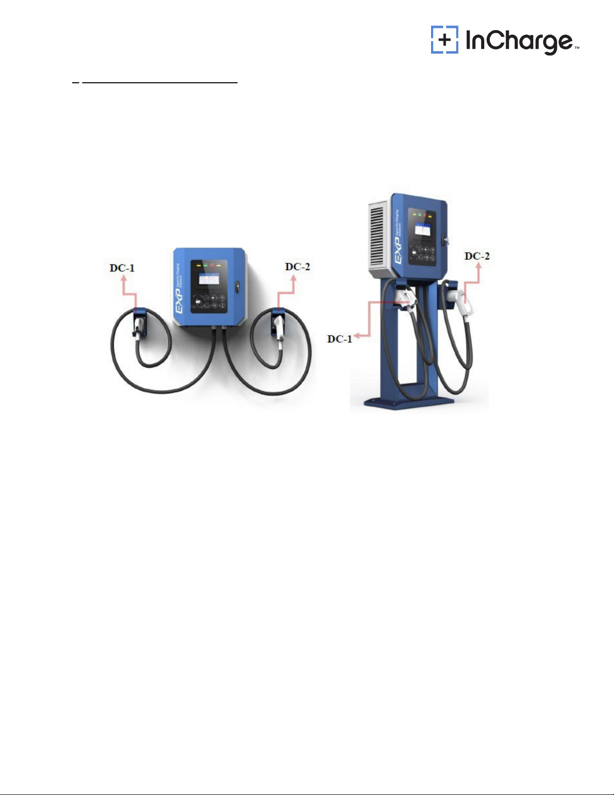
3Product Parts Presentation
The charging system is composed of DC charging cabinet and DC charging connector. The
System can be installed outdoors.
The ICE-30 fast DC Charger has various possible output combinations as shown below :
Figure 1: External View of ICE-30

9
4Installation
4.1 Safety and compliance
Since the working voltage inside the charging system is very high and the current is very large, the
following rules should always be observed to ensure personal safety:
Only personnel who have received the training of the charging system and fully mastered the
knowledge of the charging system can install the charging system. During installation, always
observe the safety precautions mentioned in this document and all relevant National Safety
Regulations.
It is necessary to make sure that the charging system DC output is disconnected in the case
of operation inside the charging system. The mains input of the charging system must also be
disconnected.
4.2 Grounding instructions
An equipment grounding conductor or a grounded, metal, and permanent wiring system is required
for the EVSE charger connection. This should be run with circuit conductors and connected to the
equipment grounding bar or lead on the EVSE.
4.3 Unpacking and visual inspection
Check that the exterior packaging has not been damaged by mechanical impacts or any
accidents during transportation
If applicable, check that the exterior panels of the ICE Charger are in perfect condition
Check that the interior of the Charging Station is clean
Check that the door of the Charging Station is working properly
Check for proper Charging Station protective ground connection point, which should be
interconnected with the low voltage switchboard ground connection during the installation
4.4 Assembly/placing instructions
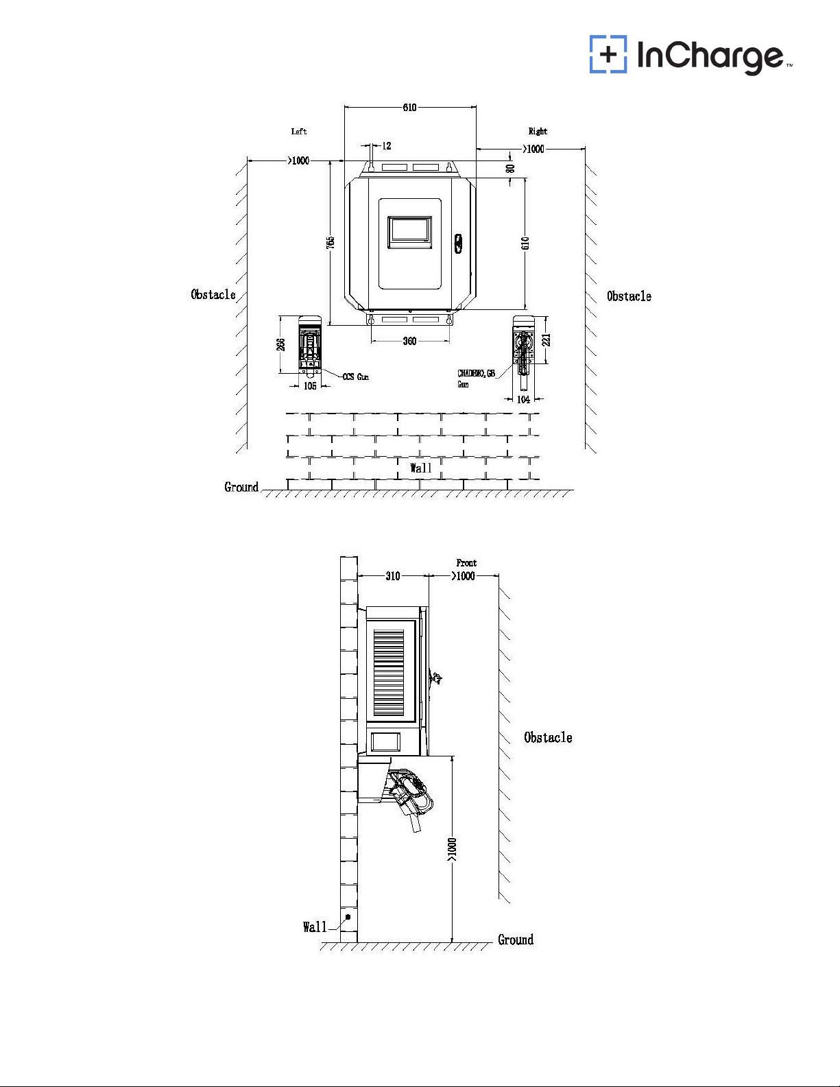
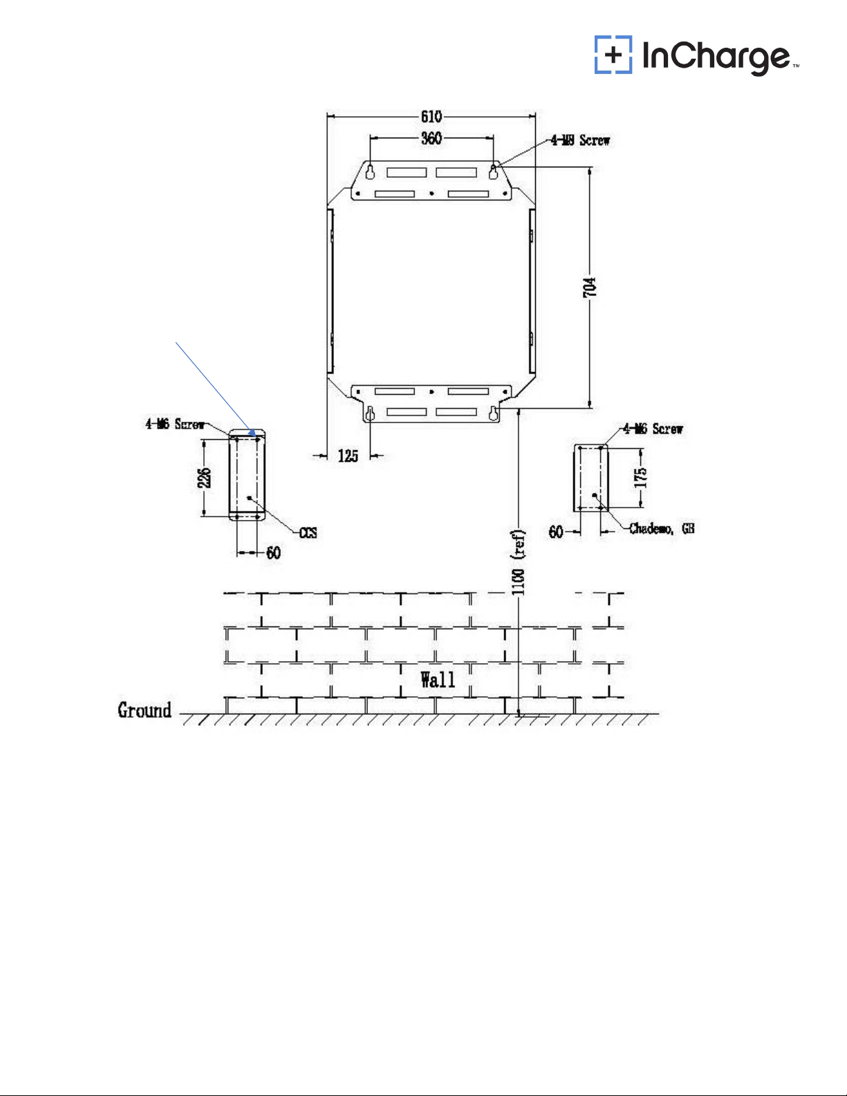
4.4.1 Anchoring to the wall
The wall mounted assembly consists of a back plate and two charging gun holsters. The EVSE
is fastened to the wall via the back plate.
The figure below shows the power cabinet drilling layout
The position of cable entrance is indicated by the red line in figure 2 below
10
Figure 2: Drilling and Conduits layout
Figure 3: ICE-30 Space Requirement
11
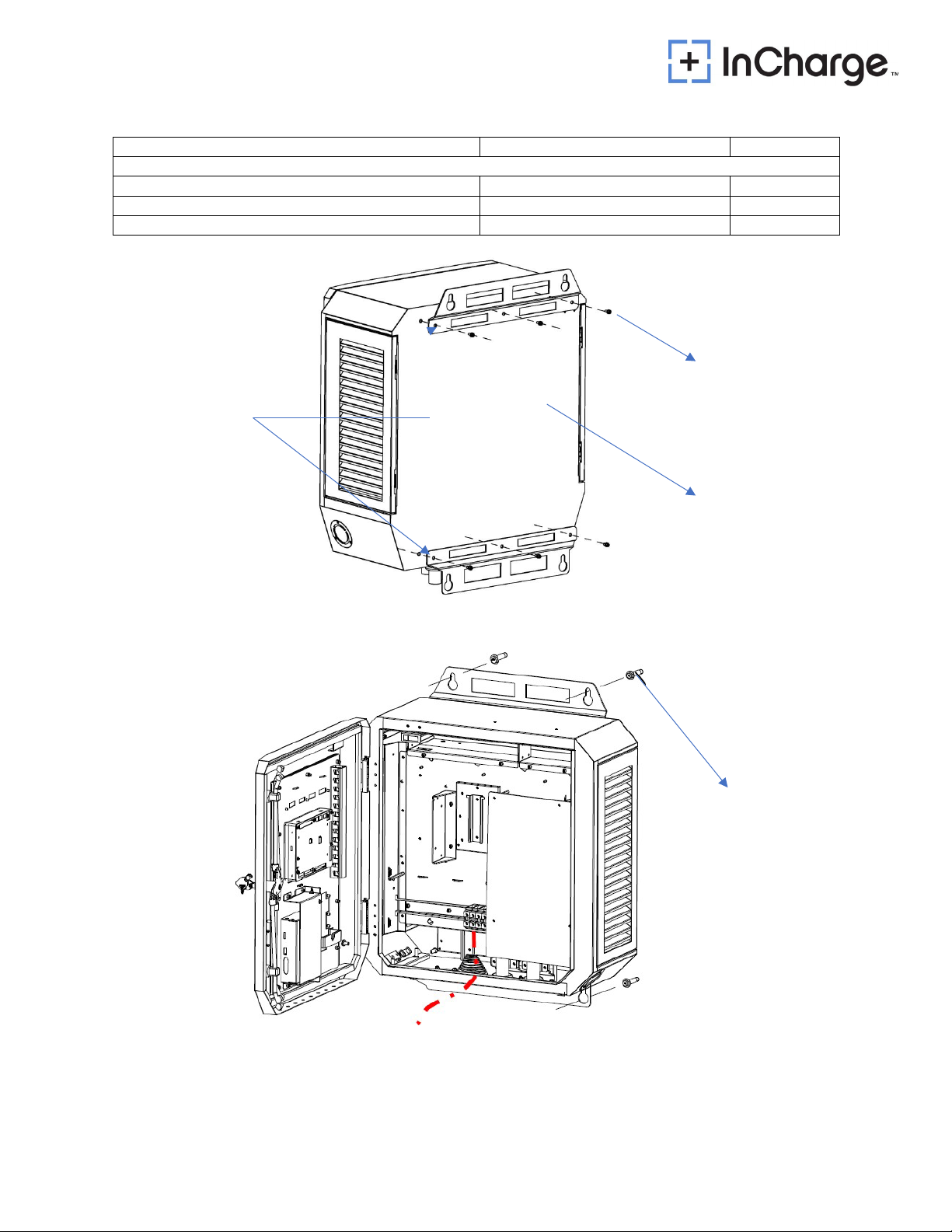
4.4.2 Table
Position
Screw Specification
Quantity
Wall Mounted
Between the back plate and the body
Combination screw, M6 * 16mm
6 pcs
Between the back plate and the wall
Expansion screw, M8 * 30mm
4 pcs
Between the gun holster and the wall
Expansion screw, M6 * 16mm
3 pcs/gun
M6 * 16, 6pcs
Combination Screw
Backplane
Body
Figure 4: ICE-30 Bracket bolt pattern
M8 * 30, 4pcs
Expansion Screw
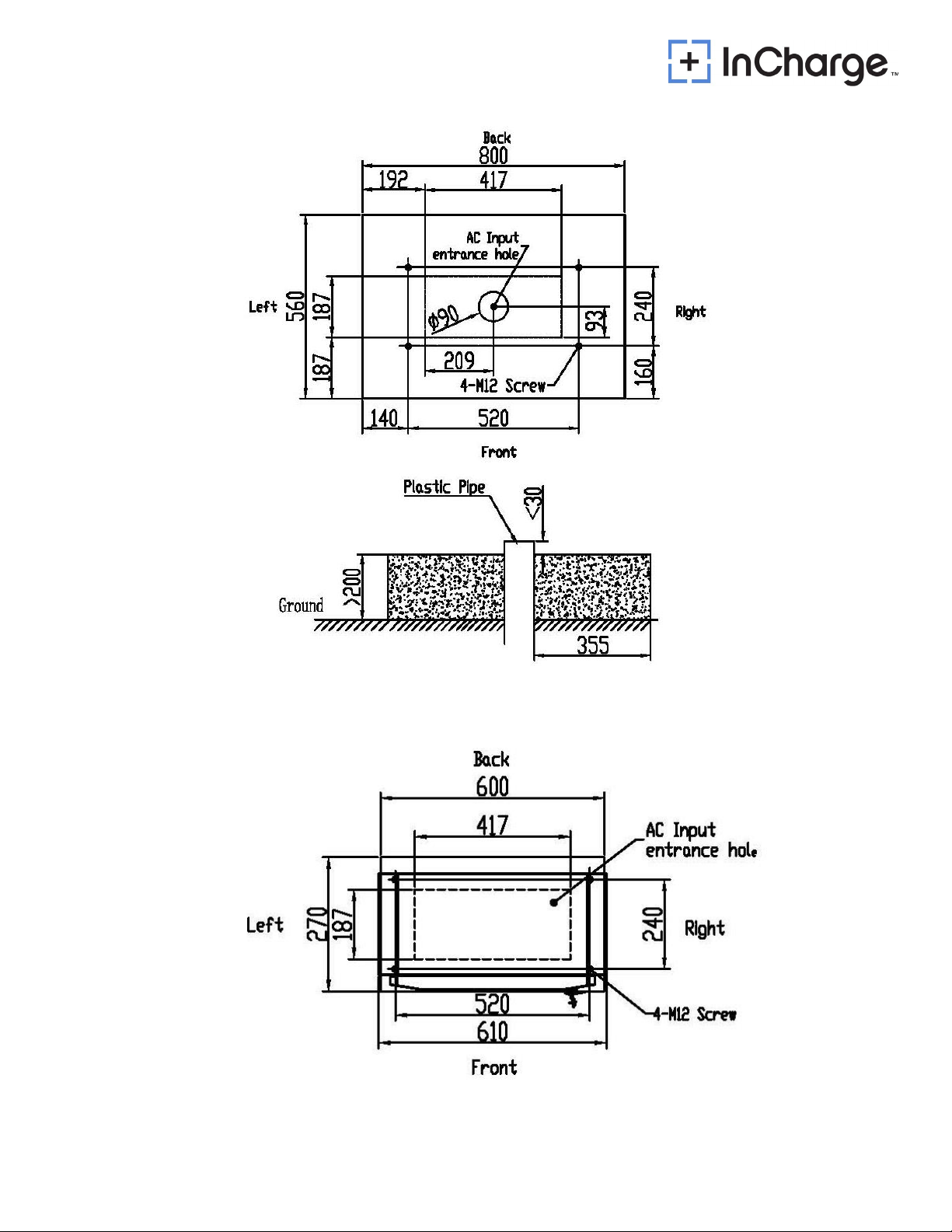
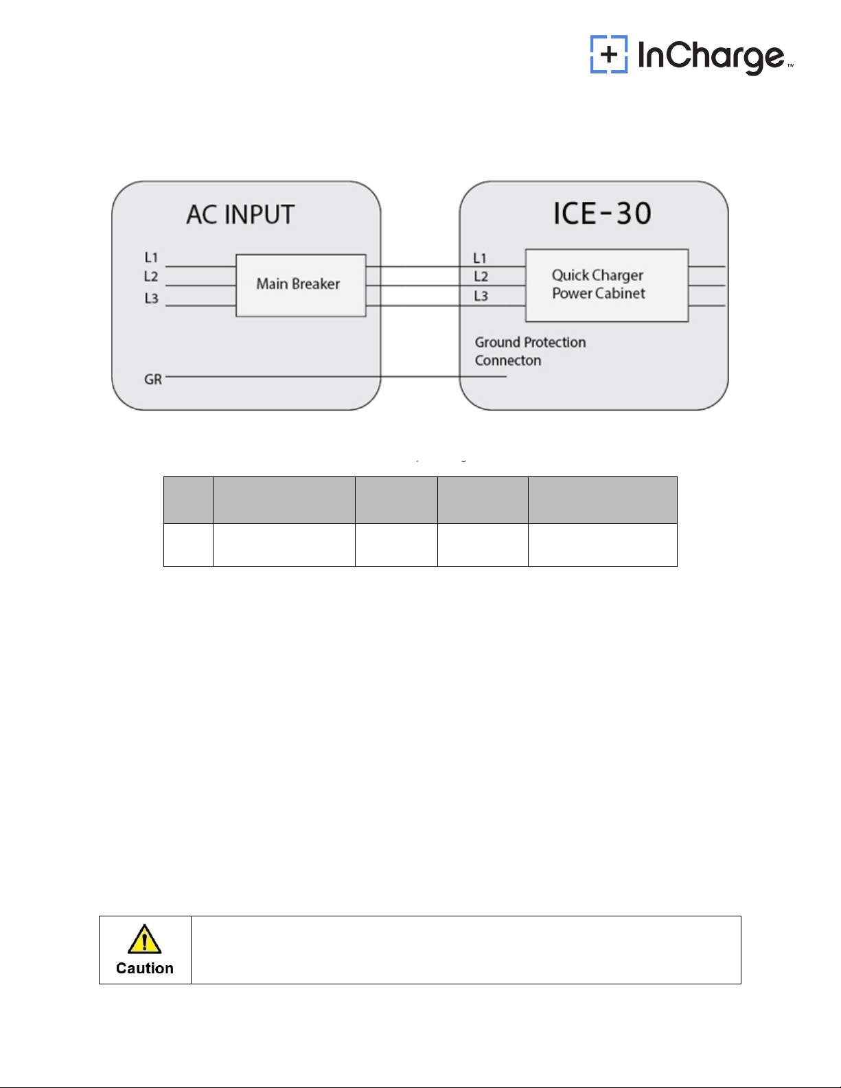
Figure 5: Grid input wiring
12
Figure 6: Back hole dimensions
M6 * 16, 4 pcs
Expansion Screw
13
Figure 7: Concrete foundation view
Figure 8: Top view
14
Table 4-AC input wiring cables
4.4.3 Power cables connections
End terminals for input wiring: 4 (four) end terminals for 3 phases + protective ground.
Figure 9: AC Input Wiring
NO. The section for AC
feed cables Amperage Max. Power
of charger
Specification of
terminal screw
1
3*185+2*95mm248A 30kW L1/L2/L3 is M6
PE is M8
Notes:
The AC feed power cables to the charger are not included.
The protective MCCB must be installed on the customer's distribution cabinet, and the upper
MCCB capacity shall not be less than 1.25 times of the input current.
It is recommended that the upper MCCB not be equipped with RCD function.
The section for feed cables is 10 to 25mm 2 . However, within this range, selected section is
based on the distance between distribution board and charger (to be decided by customer’s
electrician for installation).
This system is to be connected to a grounded, metal, permanent wiring system; or an
equipment-grounding conductor is to be run with circuit conductors and connected to
equipment-grounding terminal or lead on battery charger.
Note
Before electrical connection, all switches must be switched off.

15
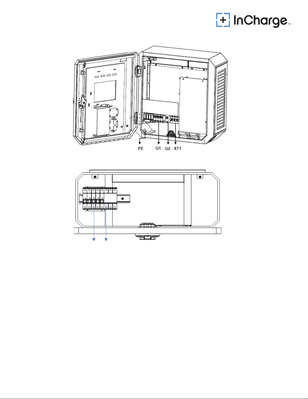
16
Q3 Q4
Figure 10: UL Wiring Diagram
※PE: Earth Bus Bar
※XT1: Power main input-Terminal Block: L1 L2 L3 N
※Q1: AC Input MCB For Rectifier Module
※Q2: AC Input RCD For Auxiliary Power
※Q3: AC output-power main input MCB
※Q4: AC output-power main input RCD
17
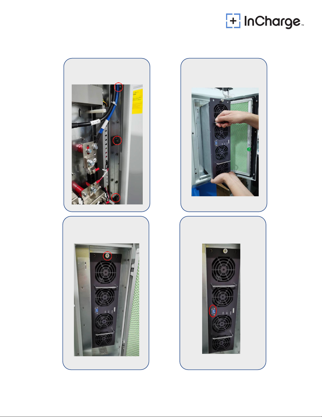
STEP-1
STEP-2
STEP-3
STEP-4
This manual suits for next models
13
Table of contents
Other InCharged Batteries Charger manuals


Popular Batteries Charger manuals by other brands

POWER ON BOARD
POWER ON BOARD VEC1095A Owner's manual & warranty information

MidNite Solar
MidNite Solar Classic 150 owner's manual

AIMS Power
AIMS Power CON120AC12VDC user manual

VOLTCRAFT
VOLTCRAFT CT-6 operating instructions

ATOMI
ATOMI Charge Stand Welcome guide

Foundations
Foundations 100-EHBP installation instructions


