InCharged ICE-180 User manual

Description
The InCharge Energy ICE-180 is an All-in-One DC Fast Charger, which
supports both CCS and CHAdeMO standards with one or two connectors.
This DC All-in-One is designed for easy installation and high reliability. This
product is easy to operate with an intuitive touchscreen display that facilitates
access control, charging status, and help menus. The ICE-180 is ideal for
auto dealers, fleet charging and a variety of parking applications where DC
charging is needed in minimal space.
Key Benefits and Features
•150 to 1000Vdc output voltage range supports new high voltage DC
charging voltages
•180kW rated output power
•User friendly control interface allows for PIN or RFID accessibility
•Tempered glass touchscreen LCD display for added durability and
daylight readability
•OCPP 1.6 standard supports integration into In-Control, In-Charge’s
EVSE management platform
•LTE Modem and LAN for connectivity to In-Control
•Compact design for space saving power-to-footprint ratio
•TUV certification to UL 2202 to ensure safety
•480V 3-phase input for high efficiency conversion
•TUV Certified
The ICE-60, 120, and 180
share the same housing
Specifications
•Available with single CCS, Dual CCS1 and CCS1 & CHAdeMO connectors
•DIN70212 and ISO15118-2 protocols supported
•Materials and Finish: Enclosure - Hot galvanized steel; Facade - Plastic; Screen - Tempered glass
•Dimensions: 29.5”(D) x 27.5”(W) x 68.9”(H) / 750mm * 700mm * 1750mm
•Weight: 900lbs / 408kg
ICE-180 All-in-One
180kW DC Fast Charger

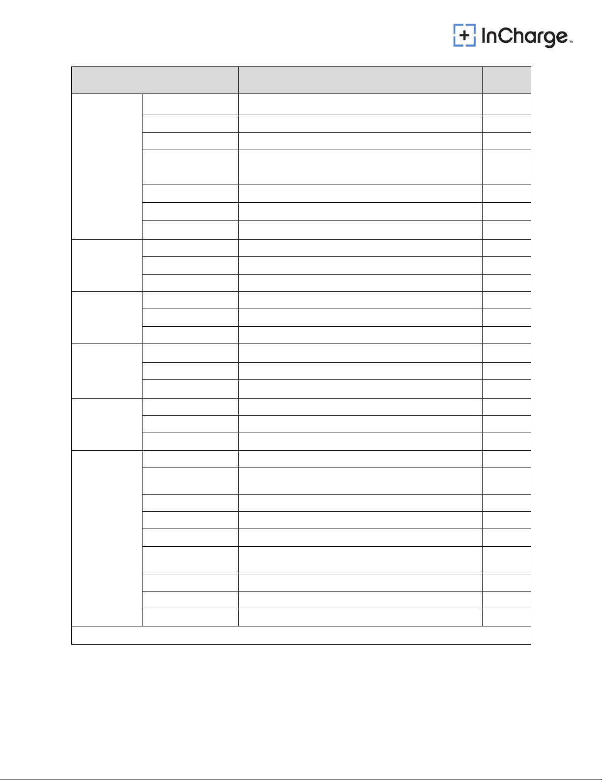
Ordering Information
Configuration SKU
ICE-180kW DC Fastcharger - Dual CCS1 ADC-180- 480-C1C1-AC1R
ICE-180kW DC Fastcharger - CCS1 & CHAdeMO ADC-180- 480-C1CH-AC1R
ICE-180 - CC CCR IDC-180-480-C1C1-AC1C
ICE-180 - CC Cold Weather IDC-180-480-C1C1-AC1R-CW
ICE-180 - C1LC1L IDC-180-480-C1LC1L-AC1R
ICE-180 - CJ CCR IDC-180-480-C1CH-AC1C
ICE-180 - CC2 IDC-180-480-C1C2-AC1R
ICE-180HC - CC IDC-180HC-480-C1C1-AC1R

Technical Specifications
Configuration SKU
Voltage 480 Vac +/- 10 %
AC Input Power Connection 3-phase: L1, L2, L3, GND
Frequency 60 Hz
Recommended breaker 300A 3W+G
SCCR 25 kAIC
Max Current Draw 222A
Power factor >0.99
THD - Current < 5%
Output Parameters Value
Voltage 150 - 1000Vdc
Current - Max 300A@300V / 300A@500V / 180A@1000V
Power - Max 180kW
System Effciency - Max >95%
Controls and Interface Value
Charging Connectors CCS1, CHAdeMO
HMI 7” TFT LCD Display
Communication OCPP 1.6J
Network Connection 4G/5G modem; LAN 10/100M
RFID ISO14443 Type A & S50, S70 MIFARE
Language English (others available on request)
Environment Value
Temperature - Operating -4°F to 113°F/ -20°C to +45°C * (Optional: -40°F / -40°C)
Temperature - Storage -40°F to 158°F/- 40°C to +75°C
Humidity 0 - 95%
Altitude - Operating 6560ft (2000 m)
Protection - Intrusion IP54, NEMA 3R; indoor and outdoor rated
General Value
Cable Length 16.4 ft (25ft available upon request)
Safety and EMI UL2202, CE, EN6100-6-3, EN61851-1/-23/-24
Certification Number 72212743
*Derating characteristics apply at extreme temperatures
GET IN TOUCH 818.697.GOEV
1433
Fifth Street, Santa Monica, CA 90401
hello@inchargeus.com | inchargeus.com
©2022 In-Charge US | All Rights Reserved


2
IMPORTANT SAFETY INSTRUCTIONS
Please read the operating instructions and notes carefully before starting operation in order
to prevent accidents. The "Caution, Attention, Warning and Danger" statements in the
products and product manual do not represent all safety matters to be observed and are
intended to supplement various operational safety precautions.
During the various operations of our products and equipment, it is necessary to comply with
relevant National Safety Regulations and strictly observe the precautions and special safety
instructions of the related equipment.
Electrical Safety
High Voltage
Danger
Since some parts of this power system are under high voltage during operation,
direct or indirect contact can be fatal.
It is necessary to comply with relevant National Safety Regulations during the installation of
the Portable DC Charger. Personnel who install and maintain this equipment must be
qualified to work with high DC voltage up to 1000Vdc and 3-phase AC voltage up to 500Vac.
It is strictly forbidden to wear watches, bracelets, bangles, rings and other conductive
objects on the wrist during installation and maintenance.
If there is water inside the DC Charger enclosure, AC power and DC connector must be
disconnected immediately. During operation in a humid environment, water should be strictly
prevented from entering the equipment.
During installation, it is strictly forbidden to operate the DC Charger and an “Operation
prohibited” signboard must be used.
Danger
Construction operation of high voltage lines may cause fire or electric shock.
The wiring area and the area where the line passes through for AC cables must
comply with national and local regulations and norms. As this device utilizes
high voltages do not attempt to install this equipment if you are not a qualified
electrician.
Tools
Warning
Special tools must be used during various operations involving high DC and AC
voltages.

3
Thunderstorm
Danger
It is strictly forbidden to carry out live installation and maintenance work during
thunderstorms.
A strong electromagnetic field will be produced in the atmosphere during a thunderstorm.
Therefore, the equipment should be well grounded to avoid damage to the equipment due
to lightning strikes.
Static Electricity
Caution
Static electricity generated by the human body may damage electrostatic
sensitive components on the circuit boards, such as the large-scale integrated
circuit (IC), etc. Before handling any patch boards, circuit boards and IC chips,
it is necessary to wear an anti-static wrist strap with the anti-static wrist strap
wire connected to Ground to avoid damage to sensitive components due to
static electricity.
Short circuit
Danger
During operation, it is strictly forbidden to short-circuit the positive and negative
of the DC Charger DC distribution or short-circuit any DC distribution polarity to
Ground. The DC Charger is a high voltage DC power supply, and short circuit
may cause damage to the DC Charger and personal safety hazards.
During work with High Voltage DC output, it is necessary to strictly check the polarity of
cables and interface terminals.
The space for DC power distribution work is compact and attention should be paid to
planning cable routing etc. before starting any installation work.
Insulated tools must be used.
During live work, attention should be paid to keeping hands, arms tools etc. away from
live high voltage parts to avoid accidents.
Others
Sharp Corners of Objects
Warning
During the handling of equipment by hand, it is necessary to wear protective
gloves to prevent injuries caused by sharp objects.
Power Cable
Caution
Make sure that the cable label is correct before the connection of cables.
Signal Cables
Caution
Signal cables should be kept away from power cables, with a minimum
distance of 100mm.

4
Table of Contents
1General Product Description ...................................................................................................................... 5
2General Characteristics.............................................................................................................................. 5
2.1 Technical Specification ....................................................................................................................... 5
2.3 Model description ............................................................................................................................... 7
2.4 Standards............................................................................................................................................. 7
3Product Parts Presentation......................................................................................................................... 8
4Installation.................................................................................................................................................. 9
4.1 Grounding instructions........................................................................................................................ 9
4.2 Unpacking and visual inspection ......................................................................................................... 9
4.3 Assembly/placing instructions............................................................................................................. 9
4.3.1 Preparation of concrete foundation........................................................................................... 10
4.3.2 Cabinet Installation..................................................................................................................... 11
4.3.3 Power cables connections .......................................................................................................... 12
4.3.4 Riser Installation
5Start-Up .................................................................................................................................................... 14
5.1 Verification and inspection................................................................................................................ 14
5.2 Switch on .......................................................................................................................................... 14
6User Manual ............................................................................................................................................. 16
6.1 Output connector
.............................................................................................................................. 16
6.1.1 CCS Connector............................................................................................................................ 16
6.1.2 CHAdeMO Connector ................................................................................................................. 17
6.2 Operation instructions....................................................................................................................... 17
Appendix 1 Engineering and Technical Parameters .................................................................................... 19
Appendix 2: Alarm information ................................................................................................................... 21
Appendix 3: Error codes and possible solutions.......................................................................................... 22

5
1General Product Description
The ICE- 60/120/180 is able to fast charge all electric vehicles compliant with Combined
Charging System (CCS) and CHAdeMO charging system standards.
IP55 for use in harsh environments
This charger is rated to charge at full power at the following temperature range: -22°F~122°F
(-30℃~50℃)
LTE wireless modem support, RFID authorization and Mobile App payment support
2General Characteristics
2.1 Technical Specification
The Technical Specifications of the ICE-60/120/180 are shown in Table 1.
This system is intended to have at least one DC output connection (CCS and/or CHAdeMO).
6
Technical Data Description Remarks
Nominal Input
Phases/Lines 3 phases + PE
Voltage
480Vac (+/-10%)
Frequency
45 – 60 Hz
Current 60:86A ;120:150A; 180: 222A
Power
60: 60kW ; 120: 120kW; 180: 180kW
Power factor
≥
0.99
System Efficiency
≥
94.5% (Full load)
DC Output
CCS1
Voltage
150~1000Vdc
Current
60: 60A @ 1000V; 120: 120A @ 1000V; 180: 180A @ 1000V
Nominal Power
180kW
DC Output
CHAdeMO
Voltage
200~500Vdc
Current
125A
Nominal Power
62.5kW
Cabinet
Dimensions(W*D*H)
700*750*1750
(
mm
)
Weight
60: 708lbs / 321kg;120: 804lbs / 364kg; 180: 900lbs / 408kg
Protection Degree
IP55
,
IK10
HMI and
Command Unit
Local interface
TFT Color touch display 7”
Communication
Router 4G/5G (GSM or LTE)
Protocol
OCPP1.6
Environment
conditions
Operating temperature1
-40°F ~ 167°F ( -40°C ~ +75°C), Derating After 131°F (55°C)
Transportation/ Storage
temperature -40°F ~ 167°F ( -40°C ~ +75°C)
Humidity
5%RH~95%RH
Place of installation
Indoor / Outdoor
Altitude
2000m (6561 ft)
Sound Noise ≤
65dB (nominal input/output power, the environment temperature
is 77°F (25°C).)
Atmospheric pressure
80KPa~110KPa
Overvoltage category
II
Protection class
Class I
Note 1:
-40℃~+75℃,derating from 55℃

7
2.3 Model description
NRTL Model Number Model Configuration Remarks
EXP-180K2-FDW-UU2 ICE-180-CC CCS-1 + CCS-1 180kW
EXP-180K2-FDW-UC2 ICE-180-CJ CCS-1 + CHAdeMO
180kW
EXP-120K2-FD-UU2
ICE-120-CC
CCS-1 + CCS-1
120kW
EXP-120K2-FD-UC2
ICE-120-CJ
CCS-1 + CHAdeMO
120kW
EXP-60K2-FD-UU2
ICE-60-CC
CCS-1 + CCS-1
60kW
EXP-60K2-FD-UC2
ICE-60-CJ
CCS-1 + CHAdeMO
60kW
2.4 Standards
The EVSE (Electric Vehicle Supply Equipment) complies with the following standards:
Table 2 Applicable Standards
Technical Data Norm Remarks
Applicable
Standards
IEC 61851-11
IEC 61851-232
IEC 61851-243
1 IEC 61851-1 2017: Electric vehicle conductive charging system. Part 1: General
Requirements
2 IEC 61851-23 2014: Electric vehicle conductive charging system - Part 23: DC electric vehicle
charging station
3IEC 61851-24 2014: Electric vehicle conductive charging system - Part 24: Digital
communication between a DC EV charging station and an electric vehicle for control of DC
charging
8
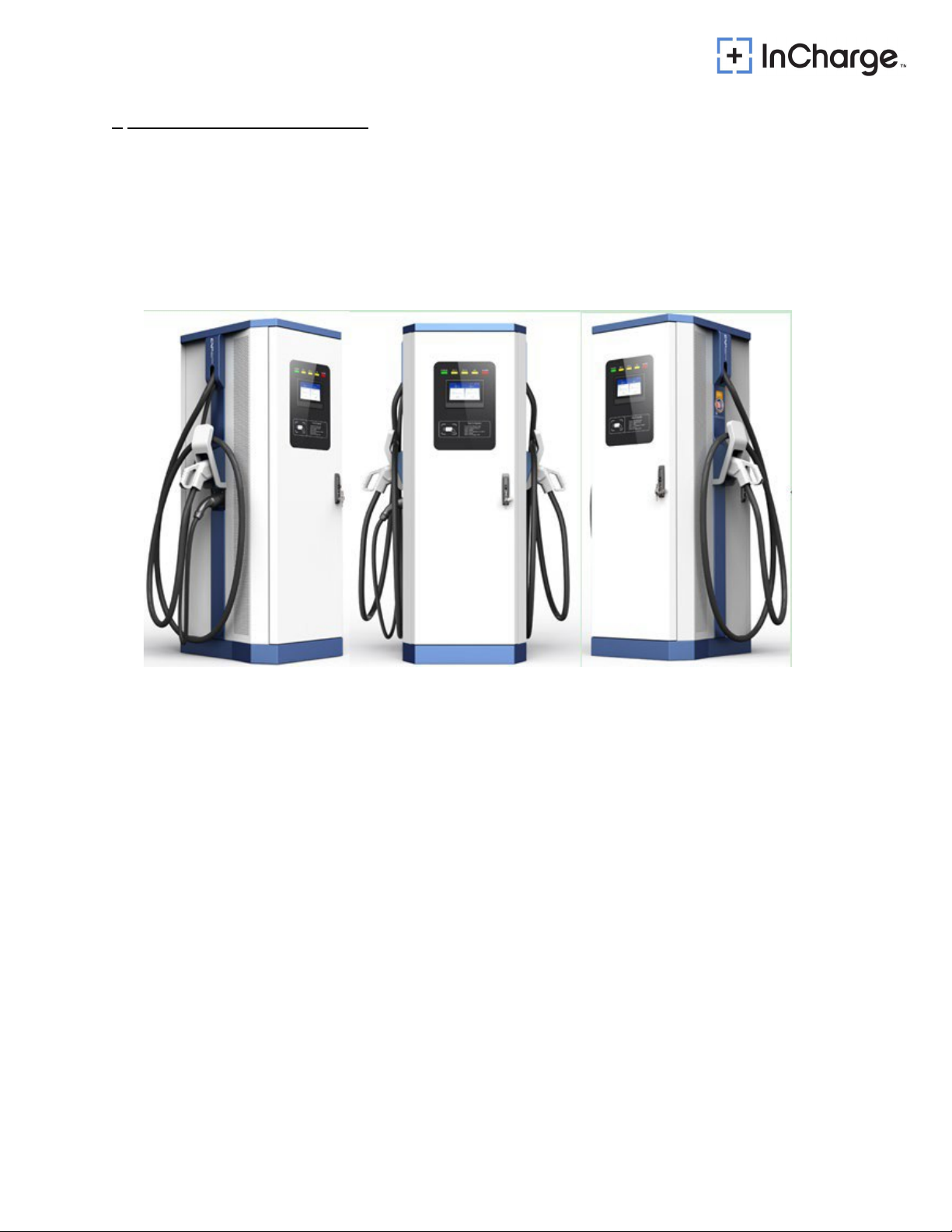
3Product Parts Presentation
The charging system is composed of DC charging cabinet and DC charging connector. The
System can be installed outdoors.
The ICE-60/120/180 series fast DC Charger has various possible output combinations as shown in
section 2.3 Model description:
Figure 1: External View of ICE-60/120/180
9
4Installation
4.1 Grounding instructions
An equipment grounding conductor or a grounded, metal, and permanent wiring system is required
for the EVSE charger connection. This should be run with circuit conductors and connected to the
equipment grounding bar or lead on the EVSE.
4.2 Unpacking and visual inspection
Check that the exterior packaging has been damaged by mechanical impacts or any accidents
during transportation
If applicable, check that the exterior panels of the ICE Charger are in perfect condition
Check that the interior of the Charging Station is clean
Check that the door of the Charging Station is working properly
Check for proper Charging Station protective ground connection point, which should be
interconnected with the low voltage switchboard ground connection during the installation
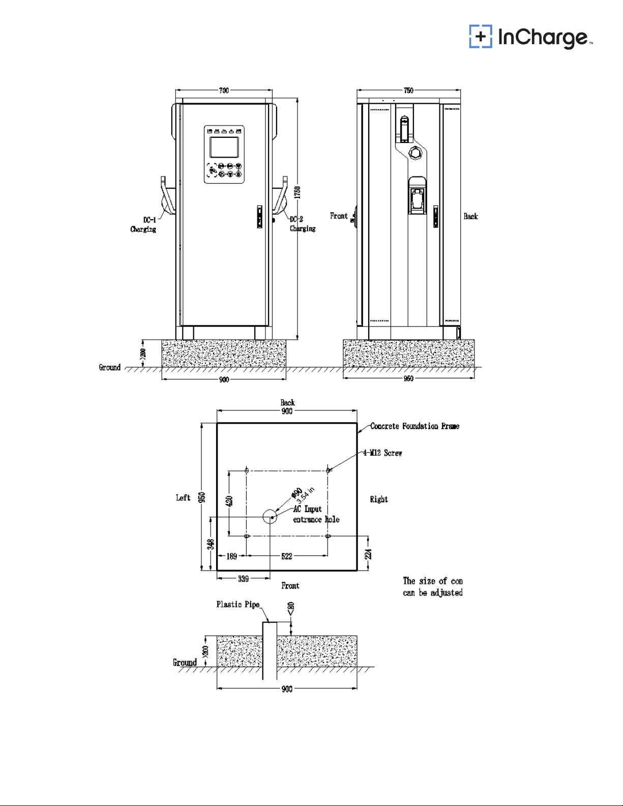
4.3 Assembly/placing instructions
As shown in the figure below, the concrete foundation should be made, and the height of the
base should not be less than 8in (200 mm) above grade.
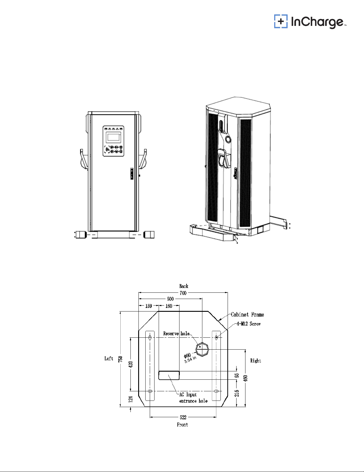
It is recommended to reserve a Φ3.5in (90mm) plastic pipe at the cable entrance, and the height
of the pipe extending out of the foundation horizontal plane shall not be more than 3.15in
(80mm).
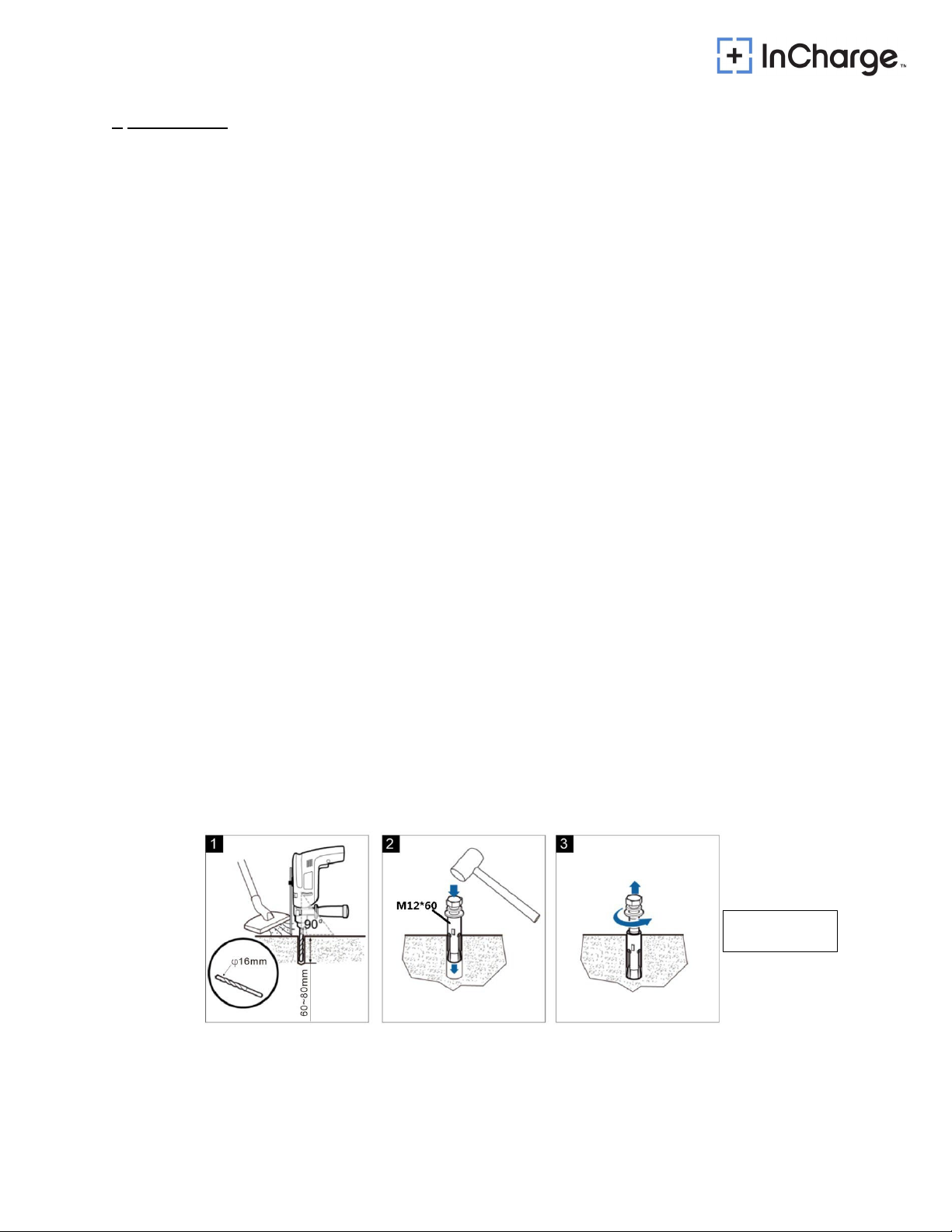
As shown in the figure below, mark the installation holes of four M12 expansion bolts on the
concrete foundation.
Open 4 holes on the concrete foundation, select the percussion bit of Ф 0.63in (16mm) type,
and use the percussion drill to drill the holes perpendicular to the ground at the above marked
hole position, with the drilling depth of 2.36in~3.15in (60mm ~ 80mm).
Use four M12 × 60 expansion bolts equipped with attached accessories, slightly tighten the
bolts, vertically put them into the hole, and knock them with a rubber hammer until all the
expansion pipes enter the installation hole.
Screw off the bolt, spring pad and flat pad in turn counterclockwise.
Figure 2: Anchor Installation
M12 Bolt: 12mm
or ½ in
10
4.3.1 Preparation of concrete foundation
Figure 4: Concrete Pad
Figure 3: Concrete foundation top view
27.56 in
68.90 in
29.52 in
35.43 in
37.40 in
>7.87 in
35.43 in
37.40 in
37.40 in
13.35 in
13.70 in
7.44 in
20.55 in
8.82 in
>7.87 in
35.43 in
3.15 in
11
4.3.2 Cabinet Installation
As shown in the figure below, the protective covers on both sides of the steel base of the
cabinet can be removed, and the cabinet can be transported to the concrete foundation by
forklift.
Align the installation hole of the cabinet base and fix the cabinet to the concrete foundation with
expansion bolts.
Figure 5:EVSE cabinet installation
27.56 in
19.69 in
6.26 in
6.30 in
29.52 in
37.40 in
4.88 in
20.55 in
8.46 in
17.72 in
2.56 in

12
Table 4-AC input wiring cables
EVSE Top View
4.3.3 Power cables connections
End terminals for input wiring: 4 (four) end terminals for 3 phases + protective ground.
Figure 6: AC Input Wiring
Max. Power of
charger
The section for AC
feed cables AWG
Amperage
Specification of
terminal screw
180kW 3*185+2*95mm23/0 320A
L1/L2/L3 is M10 PE is
M8
120kW 3*120+2*70mm22/0 224A L1/L2/L3 is M10 PE is
M8
60kW 3*95+2*50mm21 115A
L1/L2/L3 is M10 PE is
M8
Notes:
The AC feed power cables to the charger are not included.
The AC feed power cables should be no less than 90℃temperature resistant grade.
The protective MCCB must be installed on the customer's distribution cabinet, and the upper
MCCB capacity shall not be less than 1.25 times of the input current.
It is recommended that the upper MCCB should not be equipped with RCD function.
This system is to be connected to a grounded, metal, permanent wiring system; or an
equipment-grounding conductor is to be run with circuit conductors and connected to
equipment-grounding terminal or lead on battery charger.

13
Figure 7: UL Wiring Diagram

14
4.3.4 Riser Required Installation
A riser is required to be installed if the installation location has a preexisting
concrete foundation.
A riser is required to be used if the customer does not want to break ground to run
the power wires.Therefore, any modifications to the chargers housing, such as
cutting holes into the unit, will void all warranties.
The riser places the ICE-60, ICE-120, ICE-180 up six inches.
Using a riser will still allow the charges HMI to still be ADA compliant.
Comes with three plates to cover the side wall holes. All plates are the same, but holes
can easily be punched out of the side wall cover for the power lines at the desired entry
point.
Name
SKU
Rapid Base Platform RMA-DP-FD

15
5Start-Up
5.1 Verification and inspection
Check if the bolts of the AC and protective ground cables of the EVSE are correctly tightened to
the specified torque. The torque values are as follows:
M8: 20ft-lbs (15ft-lbs on M8 Ground screws)
M10: 40ft-lbs
Check the resistance between the EVSE protective ground and the low voltage switchboard
ground connection; the value must be according to local codes.
Check the resistance on the Grid AC between phases and between phase and PE. Also check
resistances between DC+/DC-/PE to ensure no dead shorts.
Check that power modules panel address setting is correct.
Before switching ON all the fuses and circuit breakers, check the supply voltage between lines:
it must be 380Vac-520Vac. Also check between phases and phase to ground. Voltage should
be 480V +/- 5% P to P and 277V +/- 5% P-PE for a 480V feed
5.2 Switch on
Switch on the circuit breakers in the charging pile, Q1 and Q2 in turn.
AC Input MCB For Rectifier Module (Q1) AC Input RCD For Auxiliary Power(Q2)

16
Wait for a few seconds. The display will present a picture as below:
Figure 8: Loading Screen
Finally, the display will present the following charging screen
CCS1+CHAdeMO Units:
Figure 9: Charging screen
Before attempting to install or start up the charger must ensure that the safety instructions in
this manual have been carefully read and observed by trained personnel. Keep this manual with
the charger for future reference.
This manual suits for next models
2
Table of contents
Other InCharged Batteries Charger manuals


