MidNite Solar Classic 150 User manual

1 | P a g e
MidNite Solar Classic
Owner’s Manual
Standard Classic Classic Lite
This Manual covers models Classic 150, 200, 250 &
250KS as well as the Classic 150, 200, 250 & 250KS LITE

2 | P a g e
The MidNite Solar Classic charge controller conforms to UL 1741, Safety for Inverters, Converters,
Controllers and Interconnection System Equipment for Use With Distributed Energy Resources,
Second Edition, May 7, 1999 with revisions through January 28, 2010 and
CAN/CSA C22.2 No. 107.1: 2001/09/01 Ed: 3 (R2006)
Notice of Copyright
MidNite Solar's Classic charge controller User’s Manual
Copyright ⓒ 2010 all rights reserved.
MidNite Solar Inc. reserves the right to revise this document and to periodically make changes to the
content hereof without obligation or organization of such revisions or changes unless required to do so
by prior arrangement.
Disclaimer
Unless specifically agreed to in writing, MidNite Solar Inc.
(a) Makes no warranty as to the accuracy, sufficiency or suitability of any technical or other
information provided in its manuals or other documentation.
(b) Assumes no responsibility or liability for loss or damage whether direct, indirect, consequential or
incidental, which might arise out of use of such information. The use of any such information will be
entirely at the user's risk.
Contact Information
Telephone: 360.403.7207
Fax: 360.691.6862
Email: customerservice@midnitesolar.com
Web: www.midnitesolar.com
YOUR MIDNITE SOLAR DISTRIBUTOR
SOLIGENT
800-967-6917
www.soligent.net

3 | P a g e
Table of Contents
Glossary of Terms.....................................................................................................................................5
Scope..........................................................................................................................................................7
Introduction..............................................................................................................................................7
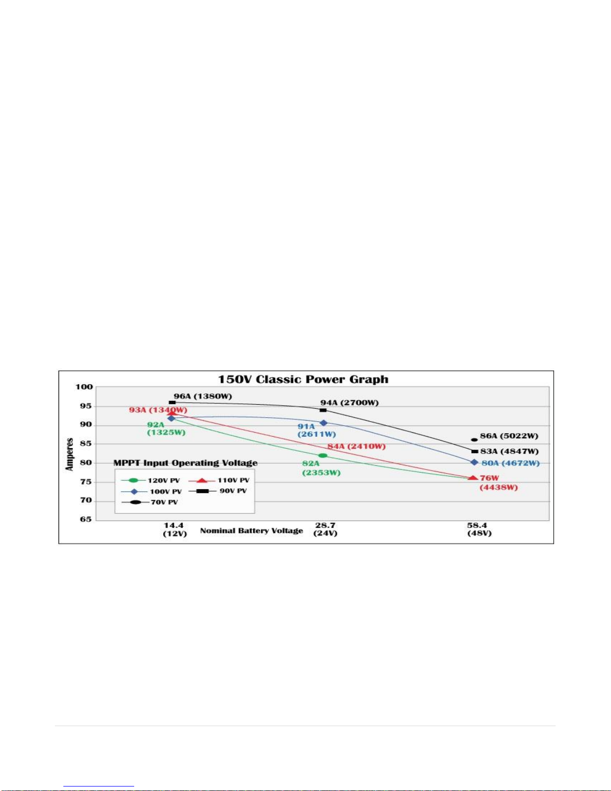
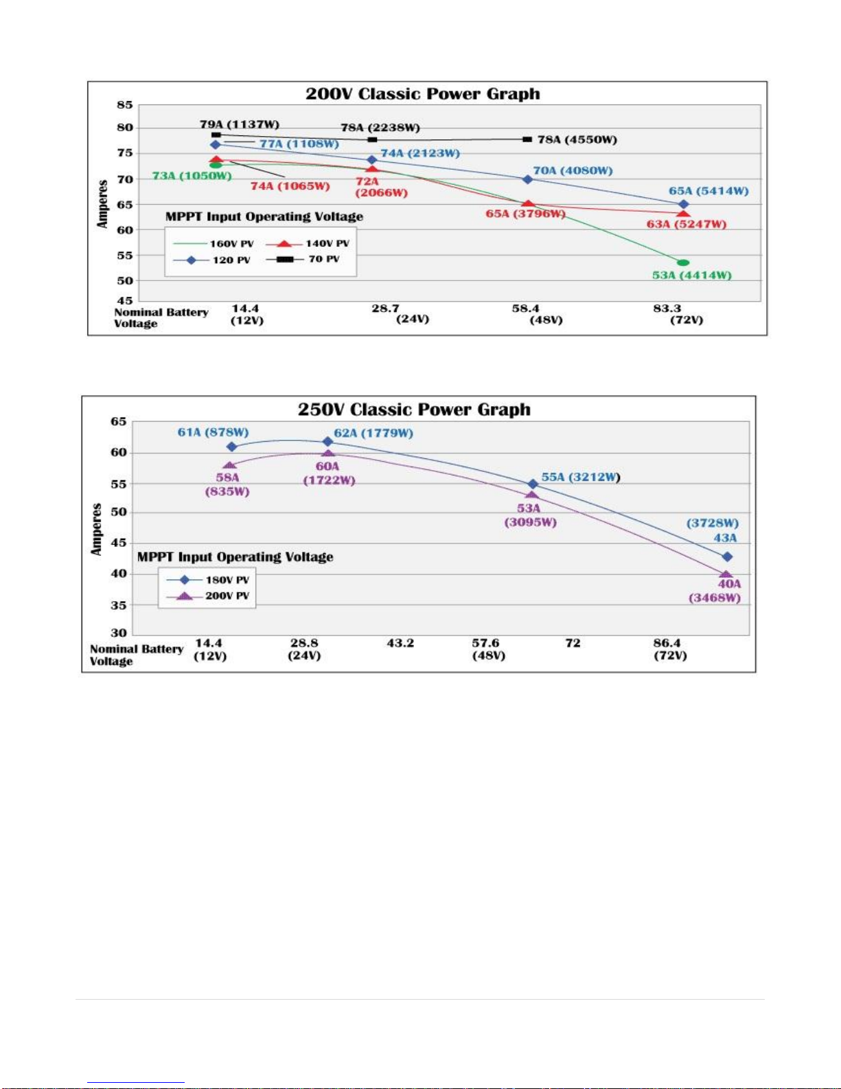
Classic Power Curves...............................................................................................................................9
Unpacking the Classic............................................................................................................................11
Removing and installing the front cover on the Classic .....................................................................12
Mounting the Classic .............................................................................................................................13
Alternative Mounting.......................................................................................................................... 15
Dimensions...................................................................................................................................... 15
Sealed or Vented.................................................................................................................................. 16
Battery Temperature Compensation ....................................................................................................16
Classic Stacking Cable Routing and Installation Guidelines.............................................................17
Battery Temperature Sensor Installation.............................................................................................18
Chassis Grounding.................................................................................................................................20
DC System Grounding........................................................................................................................ 20
DC GFP (Ground Fault Protection) .....................................................................................................21
Disabling GFP..................................................................................................................................... 21
Wiring the Classic ..................................................................................................................................22
DC Terminal Connector ...................................................................................................................... 25
Over Current Protection and Wire Size Requirements......................................................................25
Current Rating..................................................................................................................................... 25
Over Current Protection ...................................................................................................................... 26
Long Distance Wire Runs ................................................................................................................... 26
Connecting the Classic to the Clipper................................................................................................. 26
Maximum and Minimum Wire Size.................................................................................................... 27
Equalization Manual and Auto.............................................................................................................28
Equalization with the Classic Lite ...................................................................................................... 28
Equalization with the standard Classic ............................................................................................... 29
Standard Classic programming ............................................................................................................30
Commissioning the Classic (Quick Start)........................................................................................... 30
Battery Charge Stages and Meanings ................................................................................................. 30
Resting ............................................................................................................................................ 30
Mode is OFF ................................................................................................................................... 31
Adjusting Absorb, Equalize and Float Voltages.................................................................................. 31
Current Limit....................................................................................................................................... 31
LED Modes and the “Blinking Red LED”.......................................................................................... 31
Calibrating Battery and PV Voltage .................................................................................................... 32
Configuring DC Input Source............................................................................................................. 32
Configuring the Classic for Wind Input Source.................................................................................. 34
Setting the Date and Time................................................................................................................... 35
Setting Longitude and Latitude........................................................................................................... 35
Configuring Auxiliary Input/Output ................................................................................................... 35
Aux 1 Function................................................................................................................................ 39
Aux 2 Function. Output/Input......................................................................................................... 40
Setting the MNGP features ................................................................................................................. 41
Navigating the Menu's ........................................................................................................................ 41

4 | P a g e
Viewing Other MidNite Products on the Display ............................................................................... 42
Connecting Classic to Two MNGPs/Network cable........................................................................... 42
Arc Fault ............................................................................................................................................. 43
View Faults and Warning's.................................................................................................................. 44
View Logged Data .............................................................................................................................. 44
Graphical Logging Display modes ..................................................................................................... 47
Dealer Information Screen .................................................................................................................. 49
Classic Lite Programming.....................................................................................................................50
LED explanations................................................................................................................................ 50
Programming....................................................................................................................................... 51
Dip Switches ....................................................................................................................................... 51
Section 1 Switch settings explained................................................................................................. 53
Section 2 Switch settings explained................................................................................................. 54
Battery voltage and time settings.................................................................................................... 57
Using MNGP Remote to program a Classic Lite................................................................................ 58
Programming the Lite with a Networked Standard Classic................................................................ 58
Programming the Lite with the Local App.......................................................................................... 59
Clearing Faults .................................................................................................................................... 59
Notes on the Lite................................................................................................................................. 59
Explanations of Solar and Legacy ...................................................................................................... 59
Uploading New Firmware to the Classic..............................................................................................60
Connecting the Classic to the Internet .................................................................................................63
Networking.......................................................................................................................................... 63
Network Setup Through the MNGP ................................................................................................... 64
Web Access ......................................................................................................................................... 66
Local Network..................................................................................................................................... 66
Positive Ground systems........................................................................................................................66
HyperVOC ™.........................................................................................................................................67
Troubleshooting......................................................................................................................................68
Specifications Electrical.........................................................................................................................69
Specifications Mechanical .....................................................................................................................70
Default Battery charge set points .........................................................................................................71
Optional accessories...............................................................................................................................71
Regulatory Approval..............................................................................................................................71
Warranty.................................................................................................................................................72
Appendix .................................................................................................................................................73
Aux 1 and Aux 2 Graphs/Jumpers ...................................................................................................... 73
Aux 1 Voltage-Time Relation (Relay/12v) ......................................................................................... 74
............................................................................................................................................................. 74
Aux 2 Voltage-Time Relation (PWM) ................................................................................................ 74
Classic Breaker sizing......................................................................................................................... 75
Label Set from Classic ........................................................................................................................ 77
MODBUS............................................................................................................................................ 78
RS232 Jack Pin Out .......................................................................................................................... 102

5 | P a g e
Glossary of Terms
Absorb –Constant voltage charge stage to fill the batteries. The controller is regulating so maximum power will
not be seen at this time. The Absorb timer is also counting down to the switch to Float.
A-EQ-R –This will reload the Auto Equalize counters, basically it will start the counters from day 1.
AF –Arc Fault, See page 43 for more info on arc fault protection.
Arc Adjust –This menu is where you adjust the Arc Fault sensitivity. For info on Arc Fault see page 43.
A-RST –Auto reset of the Classic controller, The Classic will reboot around Midnight every night when this is
enabled. This is useful for very remote sites where a loss of internet capability for example would be a hard ship.
Aux –Auxiliary relays. The Classic has 2 relays: Aux 1 can be configured as a 12 volt signal or a dry relay, Aux
2 can be used as a PWM signal output. Refer to page 35 for more Aux info.
BLK –Bulk MPPT Mode. By using the up arrow in Tweaks under BLK you can force the Classic into Bulk
mode.
Bulk MPPT - Maximum current charge stage, the Classic is trying to bring the batteries to the Absorb voltage
set point. We are basically putting all available power into the batteries.
Comm –This Menu allows adjustment of things like Mod Bus port, USB Mode and MNGP address.
DvrtCnt –When enabled, allows the charge stage timers to continue to run when the diversion modes are hold-
ing the battery voltage just below the actual set point.
Equalize - Constant voltage charge stage to equalize the batteries. The controller is regulating so maximum
power will not be seen at this time. The Equalize timer is also counting down to the switch to Float.
EQ MPPT - Maximum current charge stage, the Classic is trying to bring the batteries to the Equalize voltage
set point. We are basically putting all available power into the batteries.
Float –Constant voltage charge stage with a lower voltage than the Absorb charge point. The controller is regu-
lating so maximum power will not be seen at this time.
Float MPPT –Maximum current charge stage, the Classic is trying to bring the batteries to the Float voltage set
point. We are basically putting all available power into the batteries.
FLT –Float mode. By using the up arrow in Tweaks under FLT you can force the Classic into Float mode.
GF –Ground Fault, See page 21 for more info on ground fault protection.
Got Comm –Indicates a lack of communication between the display and the Classic. Consult Troubleshooting
for information page 68.

6 | P a g e
Insomnia –This when enabled, will keep the Classic from going to Resting. This is intended for hydro mode
only where you may need time to open water valves and do not want to wait for the Classic to wake up.
LED-MODE –This selection lets you pick the function of the 6 visible LED’s on a standard Classic.
LMX –LoMax, This enables the Classic to track the input voltage all the way down to Battery voltage. When
disabled the Classic will stop tracking the input around 5 volts above the battery voltage. When the input voltage
is within a couple volts of the battery voltage the inductors can “Sing” this is usually not very loud and will do
no harm.
Local App –Monitoring software included with the Classic for monitoring over the Local Network or Internet.
MNGP –Midnite Graphical interface Panel. This is the graphical display included with the standard Classic
controller.
MNLP –MidNite LED interface Panel. This is the LED display that comes standard with the Classic Lite.
Mode –This menu lets you turn the charging ability of the controller On / Off as well as lets you select the DC
input source. See page 30 for info on the Mode menu.
Mod Bus –a standard protocol used for communications. We have published our protocol to allow users to in-
terface with the Classic. See page 78 for our Mod Bus protocol.
My MidNite –Web based monitoring for the Classic. (Not available yet)
NiteLog –When enabled allows the Classic to log data in the evening when the Classic is Resting.
PV Shading –This indicates the Maximum power point voltage is less than half the open circuit voltage.
Pwr Save –Allows you to adjust the time the Backlight stays on.
Resting –The Classic is not charging the battery due to low light. For reasons Resting will appear please see
page 30.
Shade –When enabled the Classic will show PV Shading on the display when the Maximum power point volt-
age is less than half the open circuit voltage.
T-Comp –Temperature compensation using a temperature sensor to measure the ambient temperature of the
battery bank and will adjust the voltage set points up or down accordingly to ensure a full battery. There are 3
parameters to set Minimum and Maximum adjusted voltage as well as volts per degree C per Cell. Typically this
is -.05 mV but please consult your battery manufacturer. See page 16 for Temperature compensation info.
Tweaks –This menu has all the advanced adjustments for the Classic. For example: Voltage off set adjustments
etc.
VBatt –Battery voltage, measured at the battery terminals of the Classic.
VOC –Open Circuit Voltage, unloaded voltage measurement.
Vpv –Input voltage, measured at the input terminals of the Classic.

7 | P a g e
Web Access –When enabled allows the Classic to send data over the internet to My MidNite’s Server for you to
view when wanted.
Scope
This Manual provides safety guidelines and installation information for the Classic charge controller. It
does not provide brand specific information about photovoltaic panels, batteries etc. Contact the
manufacturer of other components in the system for relevant technical data.
Introduction
The MidNite Classic charge controller is unique in its ability to be used for a great variety of DC input
sources. The Classic is designed to regulate DC input from PV, and Approved Hydro and Wind turbines
for other DC sources please contact MidNite Solar tech support.. The Classic 150, 200 and 250 are
designed to work with 12, 24, 36, 48, 60 and 72 volt battery banks.
The Classic250KS is designed to charge up to a 120V nominal battery bank.
The Classic can be installed stand alone or as a multi-unit networked installation.
Standard features of the Classic charge controller include:
*3 input operating voltage ranges 150, 200 and 250 VDC
*Multiple DC input options (example Solar, Wind or Hydro)
*Wizard driven setup interface including voice and help screens
*Graphical display
*Previous 180 days of operational data logged
*Internet ready
This Manual covers Classic 150, Classic 200 Classic 250 and the Classic 250KS. It covers the
installation, wiring and use of the Classic charge controller.
WARNING Warnings signs identify conditions or practices that could result in personal injury or loss of
life.
CAUTION Cautions identify conditions or practices that could result in damage to the unit or other
equipment.
MIDNITE SOLAR CHARGE CONTROLLER INSTALLATION GUIDELINES AND SAFETY
INSTRUCTIONS
This product is intended to be installed as part of a permanently grounded electrical system as shown in the
system configuration sections. The following important restrictions apply unless superseded by local or national
codes:

8 | P a g e
•The System's DC Negative conductor must not be bonded to earth ground. The Classic does this with its
internal Ground Fault Protection circuitry. The battery negative and ground are not bonded together directly but
are connected together by the Classic’s internal GFP device. All negative conductor connections must be kept
separate from the grounding conductor connections. The equipment ground terminal inside the Classic must be
connected to Earth Ground for the internal DC-GFP to work. Continue
• With the exception of certain telecom applications, the Charge Controller should never be positive grounded.
• The Charge Controller equipment ground is marked with this symbol:
• If damaged or malfunctioning, the Charge Controller should only be disassembled and repaired by a qualified
service center. Please contact your renewable energy dealer/installer for assistance. Incorrect reassembly risks
malfunction, electric shock or fire.
• The Charge Controller is designed for indoor installation or installation inside a weatherproof enclosure. It
must not be exposed to rain and should be installed out of direct sunlight.
For routine, user-approved maintenance:
• Turn off all circuit breakers, including those to the solar modules, batteries and related electrical connections
before performing any maintenance.
Standards and Requirements
All installations must comply with national and local electrical codes; professional installation is recommended.
The NEC in the USA requires a DC ground fault interrupter for all residential PV installations. NEC2011
requires an ARC FAULT detector on all charge controllers and inverters operating above 80VDC. Both of these
devices are built into the Classic.
DC and Battery-Related Installation Requirements:
All DC cables must meet local and national codes.
Shut off all DC breakers before connecting any wiring.
Torque all the Charge Controller’s wire lugs and ground terminals to the specs found on page 19.
Copper wiring must be rated at 75° C or higher.
Keep cables close together (e.g., using a tie-wrap) as much as possible to reduce inductance.
Ensure both cables pass through the same knockout and conduit to allow the inductive currents to
cancel.
DC battery over-current protection must be used as part of the installation on the input and output.
Breakers between the battery and the Classic must meet UL489 standards.
Breakers between the DC source and the Classic must meet UL1077 or UL489 standards.
Design the battery enclosure to prevent accumulation of hydrogen gas at the top of the enclosure. Vent the
battery compartment from the highest point to the outside. A sloped lid can also be used to direct the flow of
hydrogen to the vent opening. Sealed (AGM, Gel etc) batteries do not normally require ventilation. Consult your
battery manufacturer for details.
WARNING: PERSONAL PRECAUTIONS DURING INSTALLATION
WARNING BATTERIES PRESENT RISK OF

9 | P a g e
ELECTRICAL SHOCK, BURN FROM HIGH SHORT CIRCUIT CURRENT, FIRE OR
EXPLOSION FROM VENTED GASES. FOLLOW PROPER PRECAUTIONS.
Someone should be within range of your voice to come to your aid if needed.
Keep plenty of fresh water and soap nearby in case battery acid contacts skin, clothing, or eyes.
Wear complete eye protection. Avoid touching eyes while working near batteries. Wash your hands with
soap and warm water when done.
If battery acid contacts skin or clothing, wash immediately with soap and water. If acid enters an eye,
flood the eye with running cool water at once for at least 15 minutes and get medical attention
immediately following.
Baking soda neutralizes lead acid battery electrolyte. Keep a supply on hand in the area of the batteries.
NEVER smoke or allow a spark or flame in vicinity of a battery or generator.
Be cautious to reduce the risk of dropping a metal tool onto batteries. It could short the batteries or other
electrical parts that can result in fire or explosion.
Never wear metal items such as rings, bracelets, necklaces, and watches when working with a battery or
other electrical circuits. A battery can produce a short circuit current high enough to weld a ring or the
like to metal, causing severe burns.
Classic Power Curves
Figure 2.1
Figure 2.2

10 | P a g e
Figure 2.3
Figure 2.4

11 | P a g e
The graphs above represent the max power output for a given input for each Classic. Using and understanding
these power graphs will help maximize Classic’s output power and aid in selecting wire and breaker/disconnects.
The built in set up wizard also helps select breakers and wire sizes. Notice that lower battery voltages and lower
PV input voltages result in higher continuous output power. The PV voltages listed are for reference and are not
intended to be the only PV voltages supported. The battery voltages listed show the most used battery bank
configurations. Other voltages are also supported. The Classic battery voltage parameters are fully user
adjustable.
For example: if you are using a Classic 250 and 48v battery bank, the maximum continuous output power
based on 25 degree C ambient is 55 amps when using a PV array that yields a Maximum Power Voltage of 180
volts. The same set up using a bit higher voltage modules that result in a 200V Maximum Power voltage will
result in only 53 amps. Although 55 to 53 amps is not a significant change, it does give you the idea that all
things being equal, lower voltages are a bit more efficient.
Unpacking the Classic
When you receive your Classic you will want to unpack it and make sure everything is there and in
good shape. Refer to Figure 1.1. Included in the Classic package should be:
*Classic charge controller
*Battery temperature sensor
*Knock out covers 4 screened
*User’s manual DVD, printed installation instructions
*USB cable for upgrading Firmware
**Snap on upper vent cover
**Knock out covers 4 solid
**Note. These items are optional and do not ship as standard equipment. Email
customerservice@midnitesolar.com for more information or if anything is missing or damaged.

12 | P a g e
Removing and installing the front cover on the Classic
Removing the front art deco cover is required to gain access to the wiring compartment.
Be aware if this is not the first removal of this cover there is a cable connecting the cover to the
electronics. Do not pull hard or fast as damage could occur.
To remove the front cover of the Classic in preparation for installation, remove the 4 Phillips head
screws with a #2 Phillips screwdriver. Lift the front half of the Classic casting off. You will need to
unplug the display cable. It works the same as any phone cable.
To re-install the front cover of the Classic you will need to plug in the display cable and carefully route
it around the components on the circuit board as you set the cover in place. See Figure 1.2 Do not force
the cover if it does not seat into place easily stop and look for any cables or wires that may be
interfering. With the cover seated in place install the four Phillips screws with a #2 Phillips screwdriver.
Figure 1.2

13 | P a g e
Mounting the Classic
The following section covers typical mounting arrangements. If you require additional details that are
not covered here please contact our technical support team. The Classic is designed to be directly
mounted onto the MidNite Solar E-Panel. The Classic can also accommodate other installation methods
as well. Mount in an upright position out of direct sunlight when possible. For your convenience the
Classic has four one inch knock outs that are pre cast. The Classic has mounting locations and conduit
locations are similar to other brands of charge controllers to facilitate ease of upgrading older
technologies.
Mounting the Classic directly to the E Panel:
*Remove the front cover of the Classic.
*Install the mounting bracket on the E Panel and start the upper mounting screw into the bracket
leaving it about half way out so you can hang the Classic on this screw.
*Install the 1 inch close nipple into the E Panel as shown in the E-Panel directions. The 1” close nipple,
3 locknuts and 2 plastic bushings are included with each E-Panel. One locknut acts as a spacer.

14 | P a g e
*Carefully hang the Classic on the screw in the bracket and slide it over the close nipple see figure 1.3.
*Install the lock nut and bushing on the close nipple and tighten the screw in the mounting bracket.
*Don't install the front cover until you complete the wiring of the Classic.
Figure 1.3B Classic Mounted to side of E-Panel Figure 1.3C Nipple, locknuts and bushings
that come with every E-Panel
Figure 1.3D Classic mounted to the side of a MidNite Solar E-Panel
Figure 1.3A Charge controller
bracket mounted to the E-Panel. The
bracket comes with every E-Panel

15 | P a g e
Install locknut here to act as a spacer.
Alternative Mounting
To mount the Classic to a plywood surface use 1 1/2” wood screws in
the top key hole slot hole and the holes in the wiring compartment.
Taking care to make sure the Classic is Plumb and Level.
Dimensions
See page 70 for more details.

16 | P a g e
Sealed or Vented
The Classic has the ability to be sealed for protection from salt air or dust. It comes from the factory
Vented. If you live in a dusty or salt air environment you may wish to seal the Classic. Sealing the
Classic does not make the unit water resistant. To seal the Classic install the solid plastic knock out
covers into any unused knock outs and snap the upper vent cover onto the Classic as seen in the photo
below. Note that the Classic will be slightly de-rated (puts out less power) by sealing it. Refer to the
specifications page of the owner’s manual for the ratings in the sealed mode. To obtain the parts
necessary to seal the Classic please contact our Technical Support Team. Refer to Figure 1.4 and 1.5
Figure 1.4 Figure 1.5
Battery Temperature Compensation
The Classic comes with a battery temperature sensor (BTS). This sensor raises or lowers charge voltage
based on temperature. Connect BTS to the BATT TEMP jack. (Refer to Battery Temperature Sensor
Installation 18) Battery temperature menu appears as T-Comp in the BATTERY MENU. In this menu
you can change the voltage compensation as needed. If the BTS is disconnected or shorted the Classic
will automatically use the default charge voltages non-compensated.

17 | P a g e
Classic Stacking Cable Routing and Installation Guidelines
The Classic uses a 4 conductor phone cable to communicate with other Classic's or other MidNite products. This
cable is a standard 4 conductor phone cable and simply plugs into the jack on the Master Classic labeled slave.
Plug the other end into the master jack on the second device (Slave). There is a plastic clamp located on the
circuit board for routing the network cables above the USB jack so they stay tied down and out of the way.
Refer to figure 1.7A and 1.7B
Figure 1.7A Master / Slave hook up
Master Classic
Slave Classic

18 | P a g e
Figure 1.7B
Battery Temperature Sensor Installation
CAUTION - To reduce risk of injury, charge only deep-cycle lead acid, lead antimony, lead calcium,
gel cell or absorbed glass mat type rechargeable batteries. Other types of batteries may burst, causing
personal injury and damage. Never charge a frozen battery.
WARNING: RISK OF INJURY. To reduce the risk of injury, charge only properly rated (such as 6
V 12 V and 24 V ) lead-acid (GEL, AGM, Flooded, or Nickel Cadmium) rechargeable batteries. Other
battery types may burst, causing personal injury and damage.
WARNING: Explosion hazard during equalization, the battery generates explosive gases. Follow all
the battery safety precautions listed in this guide. Ventilate the area around the battery using
ventilators with brushless motors thoroughly and ensure that there are no sources of flame or sparks in the
Vicinity.
The Classic comes with a Battery temperature sensor which plugs into the jack beside the DC Terminal
connector labeled “Battery Temp”. Refer to Figure 1.8 Route the cable through the E-panel into the
battery box. Pick a battery in the middle of the bank and about half way up the side of the battery
thoroughly clean a spot off on the case. Then remove the protective tape from the sensor and adhere the
temperature sensor to the battery. Some manufacturers use a double wall case on the battery. For
mounting a temp sensor to them please refer to the battery manufacturer's recommended procedure.
Battery Temp Sensor
included
Cable Clamp for
network cables
USB connector
USB cable is included
Ethernet connector

19 | P a g e
Figure 1.8
Insert BTS to the jack labeled BATTERY TEMP on the control board.
Figure 1.9

20 | P a g e
Chassis Grounding
In all installations the Classic chassis should be connected to ground. For systems with a battery
breaker sized 60 amps and smaller 10 AWG (6 mm2) copper is generally sufficient. For systems with a
battery breaker sized 100 amps and smaller 8 AWG (10 mm2) copper is required. For grounding
conductor requirements on your specific installation please consult your local electrical code. The
chassis grounding terminal is in the upper right corner of the electrical connection compartment see
DC System Grounding
The Classic charge controller is designed to work with Negative Ground, Positive Ground or
Ungrounded power systems. In grounded systems, dc negative may be connected to ground either
externally or by using the Classic’s internal grounding jumper, shown on figure 2.1. The internal
grounding jumper should only be installed when the Classic’s GFP is enabled. In a system with
multiple charge controllers the grounding jumper should be installed on every charge controller. In
Positive ground or Ungrounded systems the GFP jumper must be removed. See Figure 2.1 Also note
that with Positive ground there will be items still referenced to battery negative that can complete a
short circuit of the battery bank. These items include but are not limited to the USB Cable and the
Ethernet jack. Please contact Technical support for assistance on Positive ground systems.
Other manuals for Classic 150
3
This manual suits for next models
6
Table of contents
Other MidNite Solar Batteries Charger manuals