Incuvers IRIS User manual

!
USER MANUAL
V1.3.2

1!
!
Index
1 | DELIVERY! 2!
1.1 COMPONENTS! 2!
2 | DEVICE INSTALLATION! 2!
2.1 PLACEMENT! 2!
2.2 TRANSPORT! 3!
2.3 STACKING! 3!
3 | DESCRIPTION OF THE DEVICE! 3!
3.1 INCUBATOR ATMOSPHERE! 3!
3.2 SUPPLY CONNECTIONS! 4!
3.3 INTERNAL WORKING AREA! 5!
4 | GETTING STARTED! 6!
4.1 PREPARING THE INCUBATOR CHAMBER FOR USE: DECONTAMINATION! 6!
4.2 GAS CONNECTION! 7!
! 8!
4.3 POWER SUPPLY CONNECTION! 8!
4.4 SETTING UP IRIS! 9!
4.5 !WORK WITH KNOB AND DISPLAY! 9!
5 | TROUBLESHOOTING!12!
6 | SHUT DOWN!13!
6.1 SHUTTING DOWN THE DEVICE!13!
7 | PARTS AND ACCESSORIES!13!
8 | TECHNICAL DATA!15!
9 | APPENDIX!17!
9.1 ICON LEGEND!17!
9.2 HOW CAN I CUSTOMIZE MY IRIS?!18!
!

2!
!
1 | Delivery
1.1 COMPONENTS
Components delivered
Quantity
Incubator system
1
Shelving parts
2
Water bath tray
1
Power cable
1
User Manual
1
1.2 INSPECTION
Once you have received your device, inspect that all contents are present and
undamaged.
*If damages are detected or any components missing, please contact us
immediately.
2 | Device Installation
2.1 PLACEMENT
To ensure proper functioning and long-term use of the device, it must only be
operated in ambient working conditions including:
● Dry location;
● A level, solid surface capable of sustaining the weight of the device;
An ambient temperature-regulated room with a range of 18 °C to 35°C;
● Maximum relative humidity of 80%;
● Avoid direct exposure to sunlight;
● Devices that produce excessive heat or cooling should not be used near the
IRIS.
It is important to note that this product can consistently release N2, Air, and CO2 to
maintain proper cell culture conditions. As such, do not install this incubator in a room
without proper ventilation as required by the ZH 1/119 (Guidelines for laboratories).

3!
!
2.2 TRANSPORT
*IMPORTANT: Do not lift the device using the door or any external component (e.g.
hose connectors or LCD display) attached to the device
To transport, lift from underneath in an upright position and avoid abrupt shaking.
2.3 STACKING
The IRIS system is fully self-stackable. It is not recommended that you stack more
than 2 IRIS systems at a time. Additionally, the movement or disruption of one could
interfere with the image capture process of the other. During image acquisition, the
incubator should not be disturbed.
3 | DESCRIPTION OF THE DEVICE
3.1 INCUBATOR ATMOSPHERE
The working area within the incubator replicates the physiological conditions needed
for the preparation and cultivation of cells and tissue culture. This atmosphere is
regulated by three factors:
● Temperature;
● Humidity;
● CO2 concentration;
● O2 concentration.
Temperature: To ensure a sustained operating condition, ambient temperature within
the room must be at least 18°C and below the desired temperature of incubation.
Humidity: The water tray for the incubator chamber holds up to 2L of diH2O or dH2O
processed water. The heating of the working area within the incubator causes
evaporation of the water, creating constant humidity within the incubator. Under
working conditions of 37°C, a constant relative humidity of 95% can be achieved. The
water bath tray should be checked every week to ensure the presence of water.
*IMPORTANT: DO NOT USE regular tap or bottled water to refill the water tray
For humidification of the incubator, the following water quality is required:
● dH2O - Distilled water and autoclaved for sterilization
● diH2O- Deionized water and autoclaved for sterilization

4!
!
CO2concentration: The CO2 of the working atmosphere within the incubator can be
regulated between 0-20%. The CO2 gas supply must be of 99.5% purity or medical
grade.
O2Concentration: The O2 of the working atmosphere within the incubator can be
regulated between 0.5-21%. The N2 gas supply must be of 99.5% purity or medical
grade.
*IMPORTANT: When connecting the CO2 / N2 tubing to the supply valve, ensure that
the pressure does not exceed 10 psi or inner component pressure may burst.
3.2 SUPPLY CONNECTIONS
All supply connections are installed at the rear of the incubator.
Gas connection: The gas supply line between the tank and the incubator is
connected using a ¼’’ NTP connecting valve as shown in Figure 1.
*IMPORTANT: When connecting the N2/CO2/Air tubing to the supply valve, ensure
that the pressure does not exceed 10 psi or inner component pressure may burst.
Electrical Connection: The incubator is powered by a 12v, 10A power supply that
connects into the power jack shown in Figure 1.
Figure 1. The rear of the incubator, where the power jack and power switch are
located at the bottom right corner.

5!
!
3.3 INTERNAL WORKING AREA
The inner chamber of the incubator is a fully enclosed stainless-steel body.
*IMPORTANT: Certain internal components of the incubator may be sensitive to
strong acids/base. Do not use bleach-based cleaning products with a concentration
above 10%. We recommend cleaning the incubator with 70% ethanol and wiping down
with a paper towel.
Do not spray directly up to the imaging area. Doing so may cause irreversible damage
to the optical components.
Water bath tray: As shown in Figure 2, the water tray is positioned underneath the
lower shelving unit. This water tray should be filled at a maximum of 2L and
periodically checked to ensure water is always present.
Heating system: Heating elements are located at the back of the incubator behind
the protective shield. An internal fan ensures an even and cyclical distribution of
heat and humidity within the inner chamber.
Figure 2: Right-hand side cross-section of the incubator for movable components
positioning!

6!
!
4 | GETTING STARTED
4.1 PREPARING THE INCUBATOR CHAMBER FOR USE: DECONTAMINATION
NOTE!
Certain internal components of the incubator may be sensitive to strong acids/base.
Do not use bleach-based cleaning products with a concentration above 10%. We
recommend cleaning the incubator with 70% ethanol and wiping down with a paper
towel.
Do not spray directly into the imaging area. Doing so may cause irreversible damage
to the optical components.
The incubator is not delivered in a sterile state. Before use, the device must be
decontaminated. Prior to decontaminating the chamber:
● Remove the inner shelving components and the water bath tray from the
incubator. These can be cleaned with 70% ethanol or other non-corrosive
cleaning products.
To clean the inner chamber, perform the wipe/spray disinfection protocol as per
recommended by your surface cleaner. This is carried out in three stages:
● Pre-disinfection;
● Cleaning;
● Final disinfection.
Pre-disinfection:
1. Spray disinfectant onto the surfaces of the working area and of the
accessories located inside the chamber;
2. Allow disinfectant to react as specified by the disinfectant manufacturer.
NOTE!
CO2 / O2 sensor: Do not spray disinfectant directly into the ventilation areas. Doing
so may damage the electronic sensors.
Cleaning:
1. Thoroughly remove any residues and deposits using a solution of tepid water
and dishwashing agents;
2. Wipe surfaces cleaning using a clean cloth;
3. Remove cleaning liquid from water tray and wipe all surfaces of the work area
dry;
4. Wipe accessories dry.

7!
!
Final disinfection
1. Re-install shelving system;
2. Spray the disinfectant onto the surfaces of the working area and the
shelving once more. Wipe down dry;
3. Allow disinfectant to react as specified by the
manufacturer.
4.2 GAS CONNECTION
*IMPORTANT: CO2/N2 gas quality must be of 99.5% purity or medical grade.
*CAUTION
Overpressure: The operating pressure of the gas supplied to IRIS cannot exceed 10
psi. Over-pressurization may result in regulation failure and bursting. It is
recommended to set the gas supply level to 10 psi before connecting any supply to
the device.
Connecting CO2 supply:
The CO2 valve is located at the back of the incubator as shown in Figure 3. Firmly slide
your 1/4” tubing over the barbed valve until all barbed edges are within the tube. Lightly
pull on the tubing to ensure a tight fit. If tubing appears loose, or unsecure, ensure
proper 1/4" PVC sizing and repeat.
Connecting N2 supply:
The N2 valve is located at the back of the incubator as shown in Figure 3. Firmly slide
your 1/4” tubing over the barbed valve until all barbed edges are within the tube. Lightly
pull on the tubing to ensure a tight fit. If tubing appears loose, or unsecure, ensure
proper 1/4" PVC sizing and repeat.
Connecting Air/Additional CO2 supply:
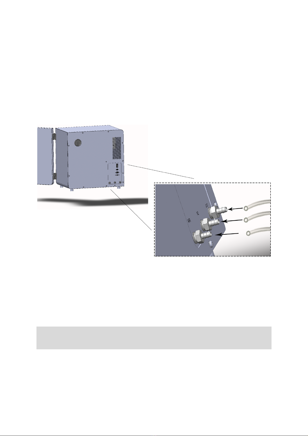
8!
!
The air valve is located at the back of the incubator as shown in Figure 3. Firmly slide
your 1/4” tubing over the barbed valve until all barbed edges are within the tube. Lightly
pull on the tubing to ensure a tight fit. If tubing appears loose, or unsecure, ensure
proper 1/4" PVC sizing and repeat.
4.3 POWER SUPPLY CONNECTION
*CAUTION: Contact with current-carrying components may cause lethal electric
shock. Before connecting IRIS to the power supply, inspect the plug and connection
line for damages. Do not connect or use power supply if damages are found.
Connecting Power supply:
Plug power supply into a voltage appropriate socket. Connect the power jack into the
power socket of IRIS as shown in Figure 1. Turn on the device by flipping the power
switch located at the back.
Figure 3: PVC tubing installation at the back of the incubator; air nozzle from
left to right is for: AIR, N2, and CO2 supply, respectively.!

9!
!
4.4 SETTING UP IRIS
Please refer to
IRIS Quick Start Up Guide
for
detailed installation guide.
4.5 WORK WITH KNOB AND DISPLAY
Upon the successful registration of IRIS, the display and knob located at the bottom right
corner of the front can be used for setting up and monitoring experiments locally along with
adjusting the optical parameters.
On the upper left corner of the screen is where the device image is displayed (Figure 4). if no
image has been previously chosen, the default Incuvers image will be present until the user
uploads a new one on the online console (See
How can I customize my IRIS
.) Likewise, users
can also customize the default name of their IRIS (See
How can I customize my IRIS
.)
Figure 4. Incubator UI in Idle State
Table of contents


