Actulux BVT IP40 User manual

1
Chain drives
Kædemotorer
Kettenantrieben
Accessories
Opérateurs de la chaîne

2
Table of Content
PAGE
Fire Switch BVT IP40 4
Fire Switch BVSA IP65 5
Wind & Rain Sensor 6
Remote Control 7
Smoke Detector 8
Thermal Differential Detector 8
Room Thermostat 9
Comfort Switch - OPUS 10
Comfort Switch - FUGA 10
HOC - Extended features for chain drives 11
LIP5 - Current Limiter and Overload Interrupter 12
LIP6 - Current Limiter and Overload Interrupter 13
LIP7 - Current Limiter and Overload Interrupter 14
Flex1 ACDC - AC Power Supply for LIP or Chain Motor 15
GSM Modem - Module for Control Panels 16
Add-On Relay PCB for indication of window position 17
Alarm / Failure Add-on Relay PCB for SV control panels 18
Actulux offers a wide range of accessories for electrical control panels and opening systems.
Accessories include among others Control Panels, Sensors, special ttings and expansion modules
allowing for additional features.

3
Accessories
Wind & Rain SensorFire Switch BVT IP40
Actulux Products
Smoke Detector Heat DetectorRemote Control
Room Detector
LIP5 LIP6
Add On - Relay PCBFlex1 GSM Modem
Comfort Switch - OPUS / FUGA HOC
LIP7
Alarm / Failure
Add On - Relay PCB
Fire Switch BVSA IP65
4
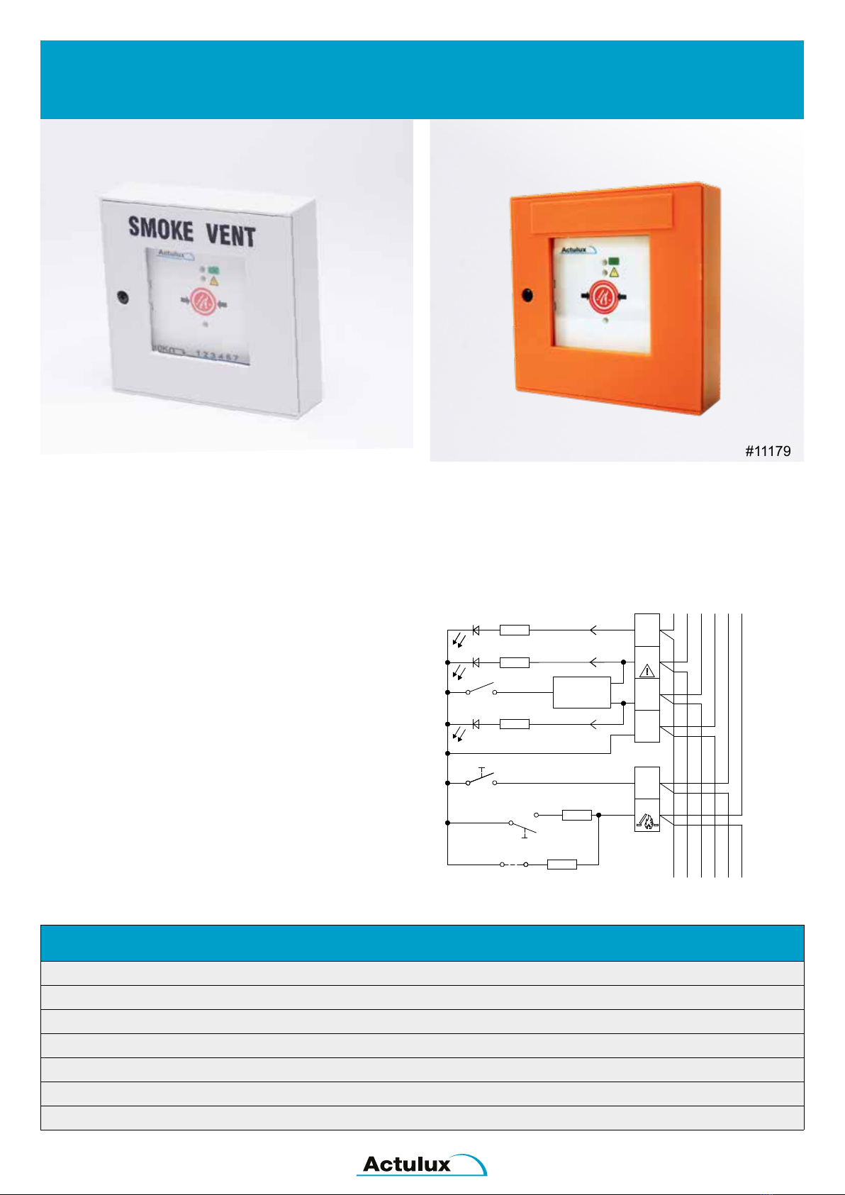
Fire Switch BVT for Smoke Ventilation Systems, IP40
for Actulux smoke ventilation systems
FEATURES
Function: Alarm (open), reset and off, sound indicator
LED indication: ’’ok”, “error” (yellow), “alarm activated’’ (red)
Size: 125 mm x 125 mm x 36 mm (W x H x D)
Colour: Grey (can be delivered in orange on request)
Protection degree: IP40
Consumption on error: 2.2 mA
Item no.: 111789 (GREY) / 111790 (ORANGE)
EASY INSTALLATION AND OPERATION
The re switch is developed to be used together with the
Actulux smoke ventilation system.
OPERATION INSTRUCTIONS
During re: Break the glass and activate the red button.
During test open the lid and activate the red button.
Closing and alarm reset: Open the lid - activate the black
reset button, alarm is reset and skylights are closed.
Connection diagram for BVT
Terminals:
1. green LED OK, lights when closing
2. Yellow LED, lights on error
3. red LED alarm, lights on emergency opening
4. ground (-)
5. -
6. re switch emergency closing (reset)
7. re switch emergency opening (re)
Jumper J1 must only be set in the last or only re switch
Denmark
111700 B
SIZE:
www.actulux.com
DWG NO.:
DRAWN BY: PSP
DATE: 07-02-17
TITLE:
SCALE:
DK 9560 Hadsund
Haandvaerkervej 2
REV:
A4 1 OF 2 2:1
Diagram BVT fireswitch
SHEET:
Actulux A/S Phone int.: +45 98 57 40 90
Fax int.: +45 96 15 28 00
e-mail: info@actulux.com
111693 Fireswitch 111784
Reset
Alarm
2
4
10 KΩ
3
OK
24V
LED
LED
Reset
7
Buzzer
2,2 KΩ
GND
6
J1
Buzzer
24V
Jumper
Alarm
1
LED
24V
Rød/Red
Rot/Rouge
Gul/Yellow
Gelb/Jaune
Grøn/Green
Grün/Vert
#111789 #111790
5
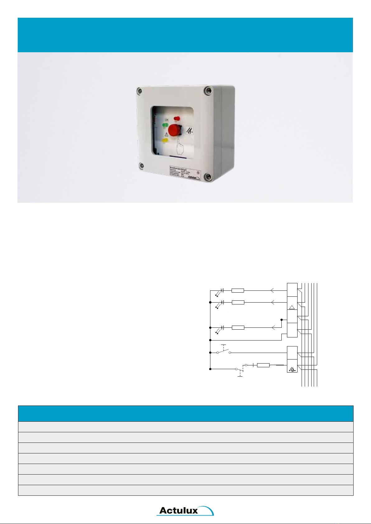
Fire Switch BVSA for Smoke Ventilation Systems, IP65
for Actulux smoke ventilation systems
FEATURES
Function: Alarm (open), reset and off
LED Indicator: ’’ok”, ’’error’’ (yellow), ’’alarm activated’’ (red)
Size: 125 mm x 125 mm x 75 mm (W x H x D)
Temperature range: (-5°C to + 40°C)
Colour: Grey
Protection degree: IP65
Item no.: 111626
EASY INSTALLATION AND OPERATION
The re switch is delivered in a IP65 box for e.g. outdoor
installation and is developed to be used together with the
Actulux smoke ventilation system.
Connection diagram for BVSA
#111626
Ω
Ω
2
6
4
13
15
11
Terminals:
2. green LED OK, lights when OK and while closing
6. yellow LED, lights on error
4. red LED alarm, emergency opening
13. ground (-)
15. re switch reset
11. re switch emergency opening
6
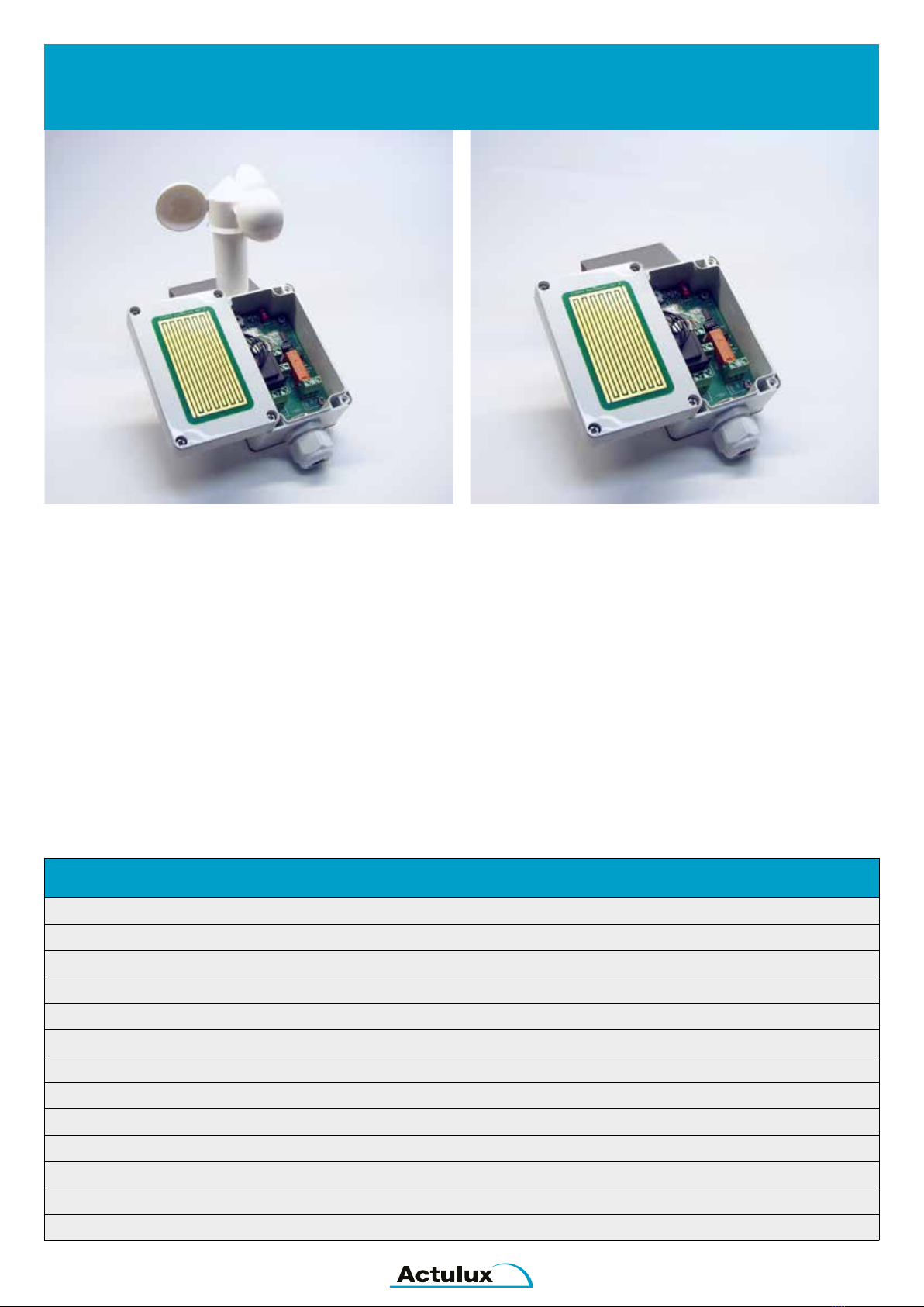
Wind & Rain Sensor, type AR/AWR 24/250
automatic control of smoke, re & comfort ventilation systems
INTELLIGENT AND ADVANCED PRODUCT
Wind and Rain Sensor #111961 consists of a wind wheel
and a rain sensor surface. It is developed for automatic
control of smoke and comfort ventilation system.
Rain Sensor #111960 consists a rain sensor surface.
Both sensors are equipped with a potential free relay with
a contact rating of 250VAC / 8A or 24VDC / 8A.
In case of wind and / or rain the relay is activated. The
settings for the wind trigger point is adjusted using rotary
switch on the main PCB.
WIRELESS CONNECTION
It is possible to connect Actulux Weather Sensor
wireless to Actulux SV/SVM Control Panel or to
Actulux Flex1 ACDC using a RF-transmitter #111892 tted
into the sensor.
Range: Line of sight approx. 400 meters.
Actulux Control Panels have to be equipped with
RF-receiver PCB:
#111894 for SVM Control Panels
#111895 for SV Control Panels
FEATURES
Power supply: 18V til 35VAC / 20V til 35VDC / 200V til 250VAC
Output contact: NO-NC 1 x potential free change-over contact
Contact rating: 250VAC / 8A or 24VDC / 8A
Dimensions: 80 x 160 x 55 mm (WxHxD / without wind wheel)
Weight: Approx. 0,7 kg
Protection class: IP65
Setting of the wind mode: Approx. 1 til 9 m / s ( 20%)
CE-marking: in accordance with the EMC-directive and low voltage directive
Connecting the controller has to be carried out by professionals
The sensor must be cleaned regularly, depending on soil degree, with a wet cloth with water - no abrasive
RF-Transmitter #111892 (optional)
Brackets for roof mounting #99600024
Brackets for wall mounting #99600025
#111961 #111960
+
-
7
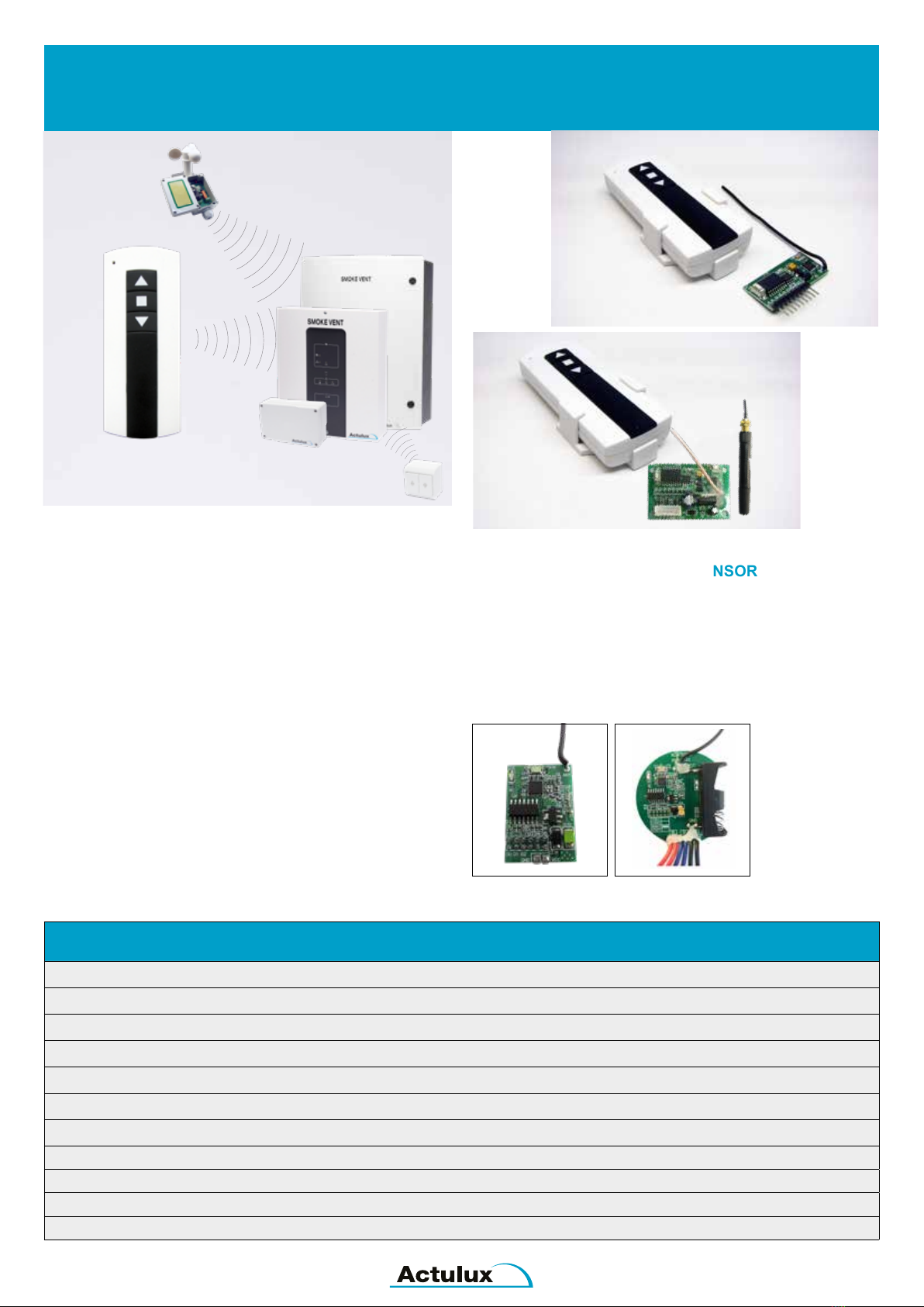
REMOTE FOR COMFORT
Enabling wireless comfort control of Actulux Control Panels
and Actulux Flex1 ACDC.
Simply t the RF-reciever PCB into the socket.
The remote control is paired with the RF-receiver PCB
from factory, but it is possible to connect more remote
controls.
HOW TO PAIR
1) Press ”program button” on the RF-receiver PCB and
hold on for 3 sec. for conrmation the LED indicator
illuminate.
2) Press the “UP-button” on the remote control
and this LED-indicator will illuminate.
3) The LED indicator will be OFF after one blink =
remote transmitter and receiver is now paired.
WIRELESS CONNECTION OF SENSOR
It is possible to connect Actulux Weather Sensor
wireless to Actulux SV/SVM Control Panel or to
Actulux Flex1 ACDC, using a RF-transmitter #111892 tted
into the weather sensor.
Range: Line of sight approx. 400 meter.
Remote Control
wireless comfort control
FEATURES
Battery: 12V/33 mAH type LRV08L
Battery lifetime: app. 2000 of 1 sec. operate function
One receiver can memorize maximum 20 transmitters / remote controls
Carrier frequency: 868.915 MHz
Range: Line of sight approx. 400 meters
Product no.: #111895 for SV Control Panel
Product no.: #111894 for SVM Control Panel and Flex1 ACDC
Product no.: #111892 RF-transmitter for weather sensor
Product no.: #111899 Transmitter for comfort (Ø50x13 mm)
Product no.: #111890 Remote control w/holder
Product no.: #111891 Reciever for SVM Control Panel and Flex1 ACDC
Set #111895
Set #111894
#111890
#111891
RF-Transmitter #111892 Transmitter #111899
8
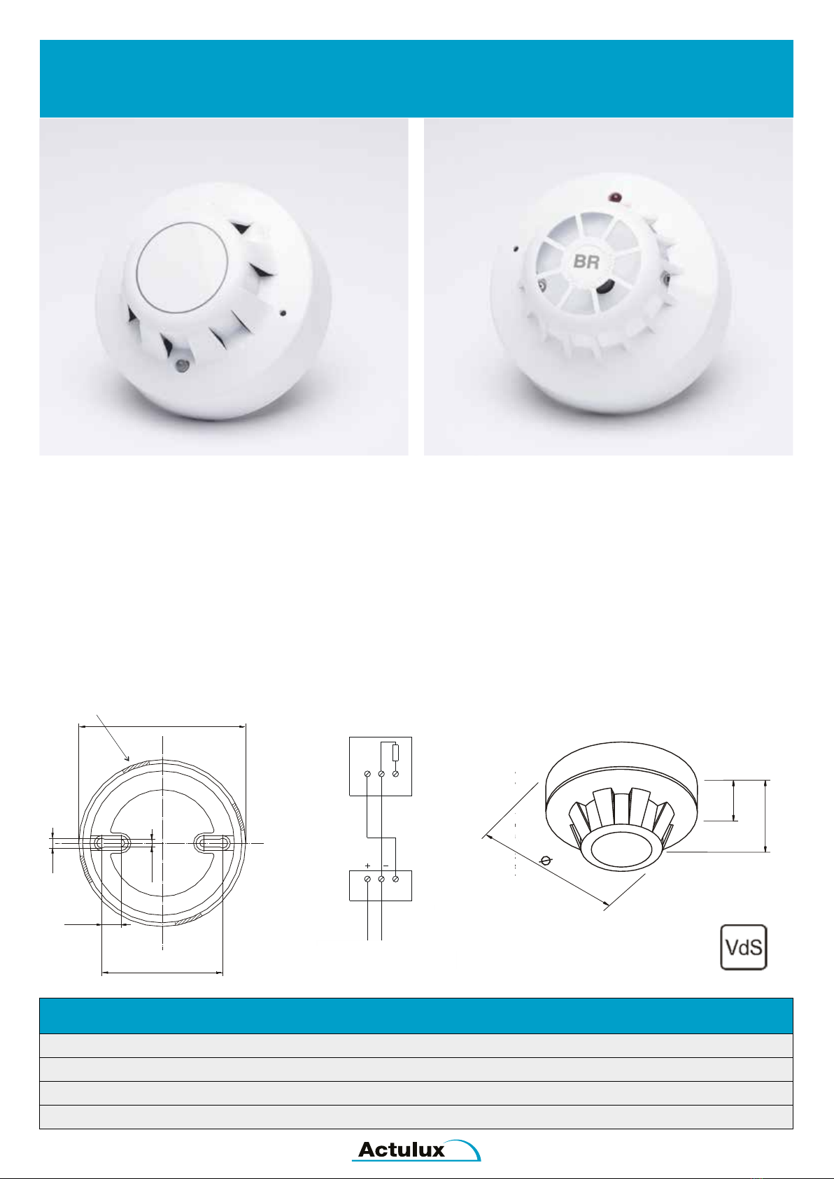
Smoke Detector / Heat Detector
detection of re
SMOKE DETECTOR
Smoke detector for early re detection with visual “release”
display. The smoke detector is including mounting base
and installation must always be horizontally beneath the
ceiling.
If automatic detectors are used, the end module
must be dismantled from connection terminal 4 and 5 at
WSC 3xx or connection teminal 15 and 16 at WSC 4xx and
mounted in the last/only smoke detector. The end module
should only be mounted here if smoke detectors are not
mounted.
THERMAL DIFFERENTIAL DETECTOR
Thermal Differential Detector for early re detection.
Alarm release in case of fast temperature increase.
Max. 75oC with visual “release” display, including
mounting base.
FEATURES
Connection voltage: 24V DC
Current consumption (rest): 0.1 mA
Colour: White
Operating temperature: -20oto 60oC
CABLE OUTLET ELECTRICAL CONNECTION
Approval no.: G200017
Varmedifferential-melder WSA 310
(Apollo 55000-127)
Teknisk Information
26
50
100
Beskrivelse:
Varmedifferential-melder til
tidlig branddetektering.
Udløsning ved hurtig temperaturstigning
samt ved maksimal temperatur på ca. 75
med optisk indikator ved udløsning,
inkl. Montagesokkel.
°C,
Tekniske data:
Forsyningsspænding:
Strømforbrug (hvile):
Kabinet:
Driftstemperatur :
24V DC
0,1 mA
Plastik,
rund, hvid
-20° til +90°C
Godkendelses-
11,5
72,5
100
6
4,5
Kabelgennemføring
x Anvendes der automatiske
meldere, skal endemodulet
afmonteres fra hhv.
Tilslutningsklemme 4 og 5 ved
WSC 3xx eller tilslutningklemme 15
og 16 ved WSC 4xx, og indsættes i
den sidste/eneste automatiske
melder!
Endemodulet skal kun monteres
her, hvis der ikke tilsluttes
automatiske meldere!
Elektriske tilslutning:
45
Tilslutning ved
WSC 3xx
Sidste automatiske melder
Første
automatiske melder
aktivt
Ende-
modul!
x aktivt
endemodul
15 16
Tilslutning ved
WSC 4xx
X Endemodul
blau
rot
Blå
Rød
L1 L2
L1 L2 L1
IN OUT
L1 L2 L1
IN OUT
CH: WindowMaster AG
(
062/289 22 22
D: WindowMaster Fenstertechnik GmbH
(
040/54 73 85-85
GB: WindowMaster Control Systems Limited
(
01 536 510 990
Head office: WindowMaster A/S
(
+45 45 67 03 00
Skelstedet 13
2950 Vedb k
Denmark
æ
www.WindowMaster.com
Første
automatiske melder
Tilslutning til brandcentral
Last smoke detector
First smoke detector
Active
end
module
Connection to control panel
#111740 #111735
Varmedifferential-melder WSA 310 (Apollo 55000-127)
Teknisk Information
26
50
100
Beskrivelse:
Varmedifferential-melder til
tidlig branddetektering.
Udløsning ved hurtig temperaturstigning
samt ved maksimal temperatur på ca. 75
med optisk indikator ved udløsning,
inkl. Montagesokkel.
°C,
Tekniske data:
Forsyningsspænding:
Strømforbrug (hvile):
Kabinet:
Driftstemperatur :
24V DC
0,1 mA
Plastik,
rund, hvid
-20° til +90°C
Godkendelses-
11,5
72,5
100
6
4,5
Kabelgennemføring
x Anvendes der automatiske
meldere, skal endemodulet
afmonteres fra hhv.
Tilslutningsklemme 4 og 5 ved
WSC 3xx eller tilslutningklemme 15
og 16 ved WSC 4xx, og indsættes i
den sidste/eneste automatiske
melder!
Endemodulet skal kun monteres
her, hvis der ikke tilsluttes
automatiske meldere!
Elektriske tilslutning:
45
Tilslutning ved
WSC 3xx
Sidste automatiske melder
Første
automatiske melder
aktivt
Ende-
modul!
x aktivt
endemodul
15 16
Tilslutning ved
WSC 4xx
X Endemodul
blau
rot
Blå
Rød
L1 L2
L1 L2 L1
IN OUT
L1 L2 L1
IN OUT
CH: WindowMaster AG
(
062/289 22 22
D: WindowMaster Fenstertechnik GmbH
(
040/54 73 85-85
GB: WindowMaster Control Systems Limited
(
01 536 510 990
Head office: WindowMaster A/S
(
+45 45 67 03 00
Skelstedet 13
2950 Vedb k
Denmark
æ
www.WindowMaster.com
Første
automatiske melder
Tilslutning til brandcentral
9
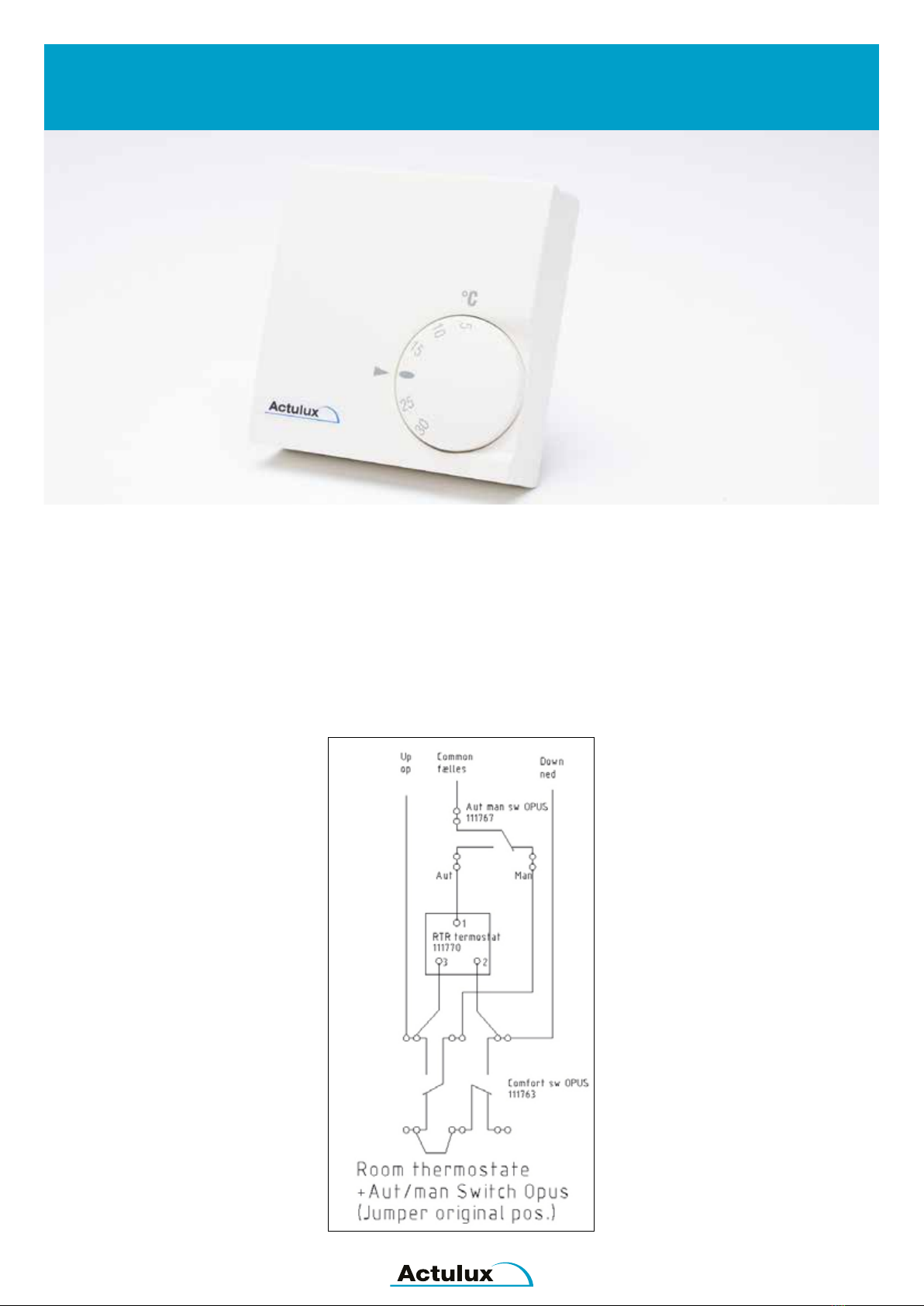
Room Thermostat
automatic opening and closing of skylights and windows
AUTOMATIC OPENING AND CLOSING OF SKYLIGHTS
The room thermostat can be used for automatic opening
and closing of skylights when the temperature in the room
exceeds the set temperature. There is approx. 1 degree
between the open and close limit.
The room thermostat is often connected with an
AUT-MAN switch so the opening can be controlled
automatically or manually.
The room thermostat can also be connected with a
weekly timer which makes sure that the window is closed
automatically, e.g. during the night. Should be used
together with a weather sensor in order to protect against
opening in bad weather.
Dimensions: 75 x 75 x 25 mm
Colour: White
#111778
10
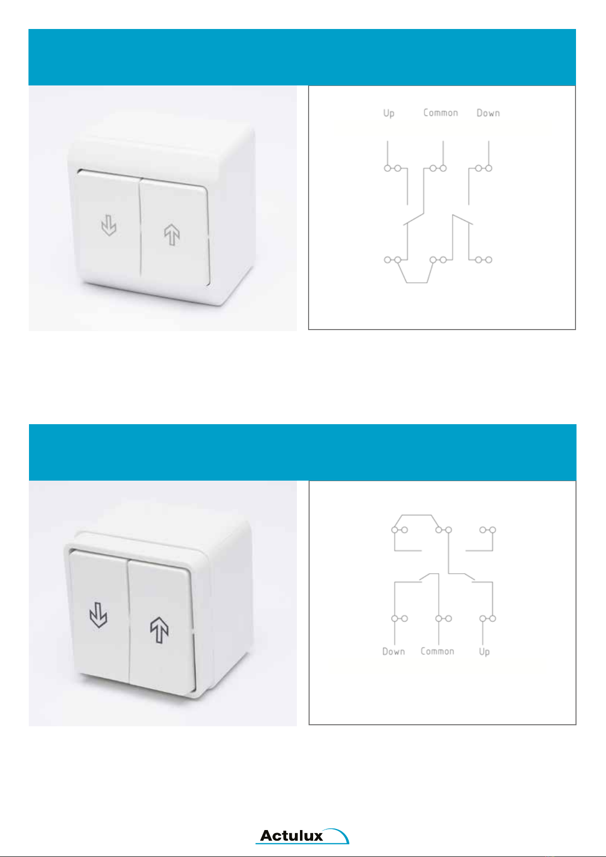
Comfort Switch, Type OPUS
manual control of comfort ventilation
MANUAL CONTROL OF COMFORT VENTILATION
Up/down switch for manual control of comfort ventilation,
e.g. in connection with 24V re and smoke ventilation
systems.
The up/down switch is delivered with housing for wall
mounting.
Dimensions: 65 x 65 x 45 mm
Please remember to mount return springs behind both
arrow keys
Comfort Switch, Type FUGA
manual control of comfort ventilation
MANUAL CONTROL OF COMFORT VENTILATION
Up/down switch for manual control of comfort ventilation,
e.g. in connection with 24V re and smoke ventilation
systems.
The up/down switch is delivered with housing for wall
mounting.
Dimensions: 50 x 50 x 40 mm
#111753
#111758
Please remember to mount return springs behind both
arrow keys
11
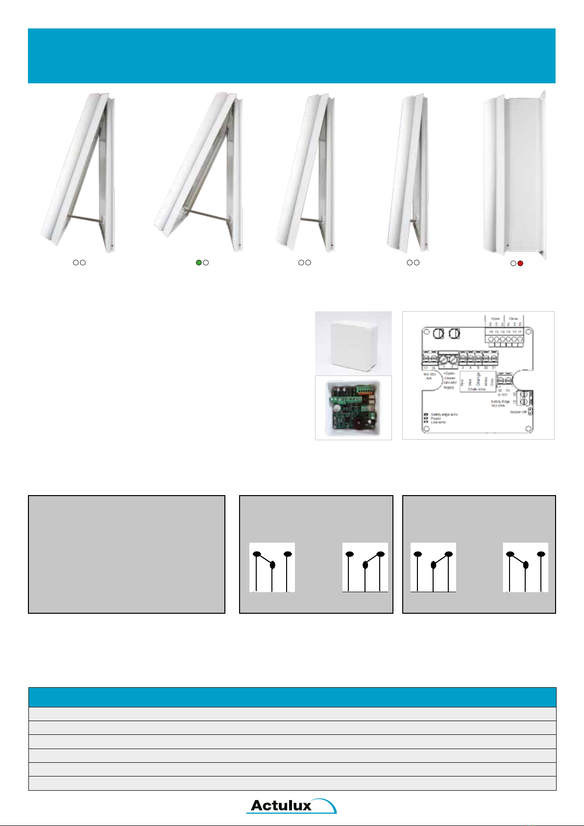
Extended features for chain drives - Type HOC
compatible with Actulux series HCM and HCV
EXTENDED FEATURES FOR CHAIN DRIVES
HOC is an advanced electronic product, which is used to
add features in new, but also already installed chain drives
(contact Actulux sales department for further information)
● Open / Close indication (bistable relays)
● Building Management System (BMS) 0-10V control
● Interface for MAYSER Safety Edge (true Anti-Pinch)
HOC is compatible with 3. generation of Actulux chain drives.
FEATURES
Power Supply: 24-36-48VDC +/- 15% Max. Ripple: 2 Volt PP
Max. power in the position relay: 30VDC / 2A
Dimensions (L x W x D): 86 x 86 x 39 mm
Colour: White / Density: IP65
Meets requirements: EN12101-2 / EN60335-1 / EN50130-4 / Marking: CE
Product number: 390420 (Standard) / 390421 (BMS 0-10V control)
INPUT = STROKE LENGTH INDICATION FOR OPEN / CLOSE
EXTERNAL CONTROL
0 - 10V = 0% - 100% (stroke length)
--------------------------------------------------
Min. 10% interval
Status Status
CLOSED +15mm NOT CLOSED
Status Status
OPEN -15mm NOT OPEN
-15 mm inwards 100% +15 mm outwards 0%
Not Open Open Not Open or Closed Not Closed Closed
NO CO NC NO CO NC NC CO NO NC CO NO
16 15 14 16 15 14 13 12 11 13 12 11
12
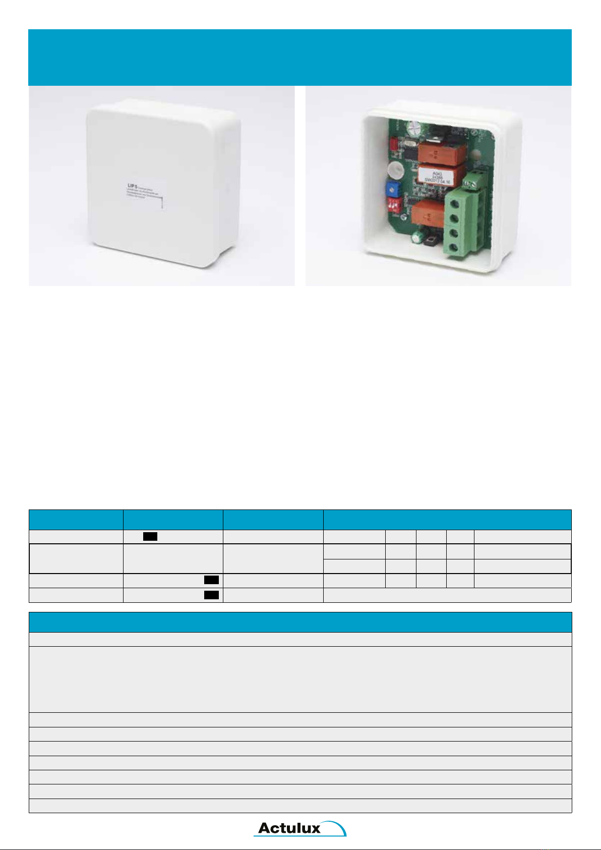
Current Limiter and Overload Interrupter - Type LIP5
intelligent and electronic current limiter
ADVANCED ELECTRONIC CURRENT LIMITER
LIP5 is an advanced electronic product that is used as current
limiter between a 24V DC or 48V DC supply
and 1 actuator.
When the adjusted current limit is reached because of the
load of the actuator, and the load of the actuator hereby
increased further, the speed of the actuator will be
atuomatically reduced.
This way the consumption will not exceed the adjusted level,
e.g. 4 amp. for 24V and 2 amp. for 48V.
BUILT IN ACTUATOR PROTECTOR
LIP5 has a built in actuator protector. This means that the
voltage will automatically be interrupted if the speed of the
actuator gets relatively very low or stops completely because
of a mechanic locking or end stop.
LIP5 is delivered in a discreet plastic box, which also functions
as a link between the supply and the actuator.
FEATURES
Supply: 24V DC eller 48V DC +/- 15%, Ripple 2 Volt PP
Current limiter: Adjustment possibilities for max. current consumption by means of a switch on the board:
Type of opening system 24V 48V
SA Power 3,0A 1,5A
SA Power 4,0A 2,0A
SA Power Mini 2,5A 1,25A
Rotary 100 2,5A 1,25A
Input resistance: Possibility to connect a 27K ohm resistance over the input clamp connection for monitoring of the line
Size (l x w x h): 100 x 100 x 50 mm
Colour: White
Density: IP54
Terminals: 16 mm²
Approved acc. to: EN60335-1
Marking: CE
CONNECTION & SETTINGS
SW off on Function Settings
1 OFF ON OFF ON
4A Max. current
Motor output
24VDC supply N/A 3A 4A 2,5A Rotary 100 / SA Mini
48VDC supply N/A 1,5A 2A 1,25A Rotary 100 / SA Mini
2 OFF OFF ON ON
3 Input resistance on = 27Kohm connected / off = 27Kohm disconnected
#121326

13
Current Limiter and Overload Interrupter - Type LIP6
intelligent and electronic current limiter
#121333
ADVANCED ELECTRONIC CURRENT LIMITER
LIP6 is an advanced electronic product, which is used as a
current limiter between a 24V DC or 48V DC supply and 1 or
2 actuators.
When the adjusted current limit is reached because of
the load of the actuator(s), and the load of the actuator(s)
hereby increased further, the speed of the actuator(s) will
be automatically reduced. This way the consumption will not
exceed the adjusted level, e.g. 3 amp. for 24V or 1,5 amp. for
48V
LIP6 can work both as single operation, i.e. connected to 1
actuator or as tandem operation i.e. connected to 2 actuators
in parallel operation.
LIP6 has a built in actuator protector. This means that the
voltage will automatically be interrupted if the speed of the
actuator gets relatively very low or stops completely because
of a mechanic locking or end stop. LIP6 is delivered in a
discreet plastic box, which also functions as a link between
the supply and the actuator(s).
FEATURES
Supply: 24VDC or 48VDC +/- 15%
Output: 2 outputs which can function independently (individually in single operation) or or in joint operation (tandem)
Current limiter: Adjustment possibilities for max. current consumption by means of a switch on the board:
Type of opening system: 24V 48V
SA Power 3,0A 1,5A for each actuator output
SA Power 4,0A 2,0A for each actuator output
2,5A Rotary 100 / SA Mini 2,5A 1,25A for each actuator output
Tandem operation: If one actuator fails, the other one stops shortly after (maximum 3 seconds)
Input resistance: Possibility to connect a 27K ohm resistance over the input clamp connection for monitoring of the line
Dimensions (l x w x h): 100 x 100 x 50 mm
Colour: White RAL 9010 / Density: IP54
Approved according to: EN60335-1 / Marking: CE
CONNECTION & SETTINGS
SW off on Function Settings
1 OFF ON OFF ON
4A Max. current
Motor output
24VDC supply N/A 3A 4A 2,5A Rotary 100 / SA Mini
48VDC supply N/A 1,5A 2A 2,5A Rotary 100 / SA Mini
2 OFF OFF ON ON
3 No function
4 Operation mode on = 2 x Single / off = Tandem
5 Input resistance on = 27Kohm connected / off = 27Kohm disconnected
6 Delay between M1 and M2 on = delay on / off = delay off

14
Current Limiter and Overload Unit - Type LIP7
intelligent and electronic current limiter
ADVANCED ELECTRONIC CURRENT LIMITER
LIP7 is an advanced electronic product that is used as current
limiter and overload unit between a 24 -36 - 48 VDC supply and
for 1 actuator (motor).
When setting for the current limiter is reached because of the
actuator load, and the load on the actuator is further increased,
then the actuator speed is automatically reduced, so that the
current consumption does not exceed the set level.
A heat resistant silicone cable is mounted as supply line.
LIP7 is available in 3 versions:
LIP7 Basis, LIP7 Tandem and LIP7 Open / Close.
LIP7 BASIS #121305
1 channel actuator protector - replaces LIP5.
LIP7 TANDEM #121306
1 channel but now with the opportunity to operate in
Tandem / Synchro mode with another LIP7 if 2 pcs. of opening
systems are mounted in the same window or skylight to prevent
damage to the window or skylight. The system stops if power to
one motor disappears.
There is also an opportunity to operate in Synchro mode where
both systems are running exactly with the same speed without
delay.
Synchro mode requires that the electrical actuators in the opening
system is mounted with “reed switches” for speed / position
indication.
LIP7 OPEN/CLOSE #121308
Same features as the LIP Tandem but also with clamps for
Open / Close indication of the window or skylight.
Open / Close indication and Synchro mode requires that the
electrical actuators in the opening system is mounted with “reed
switches” for speed / position indication.
LIP7 TA (tandem) #121306 LIP7 OC (open / close) #121308
LIP7 BA (basis) #121305
FEATURES
Power supply: 24 - 36 - 48 VDC +/- 15%, Max. Ripple: 2 Volt PP
Input resistance: Using switch on the PCB a 27kΩresistor can be engaged
over the input terminals of the supply to the line monitoring
Max. power in the position relay: 30 VDC / 2A
Size (l x w x h): 100 x 100 x 50 mm
Material: White plastic box
Compatible with previous LIP editions
Density: IP54
Silicone cable length: Standard 85 cm
Meets requirements: EN12101-2 / EN60335-1 / EN50130-4 Marking: CE
Product number: 121305 (Basis) / 121306 (Tandem) / 121308 (OC Open / Close)
CONNECTION AND SETTINGS
(*) Please note that the above power settings are standard - can also be customized to specic Actulux actuator types
DIP switch off on Function Settings*
1 OFF ON ON OFF
4A / 24VDC
Max. average current.
(Please note this is only an example - may
vary in diff. types of Opening Systems)
24V 2A 3A 2,5A 4A
36V 1.5A 2.25A 1.9A 3A
48V 1A 1.5A 1,25A 2A
2 OFF OFF ON ON
3 OFF = No 27kΩfor line detection ON = 27kΩfor 2 wire line detection (terminal 1 and 2)
↓ Only available in LIP7 TA and LIP7 OC ↓
4 OFF = Stand Alone mode (only 1 system / LIP) ON = Communication mode (set ON in both systems / LIPs)
5 OFF = Slave ON = Master (set ON only in one system / LIP)
6 OFF = Sync mode = 3 wire actuator (motor) ON = Tandem mode = 2 wire actuator (motor)
7 OFF = No delay between Master and Slave ON = 7 seconds delay between Master and Slave
8 Not in use
15
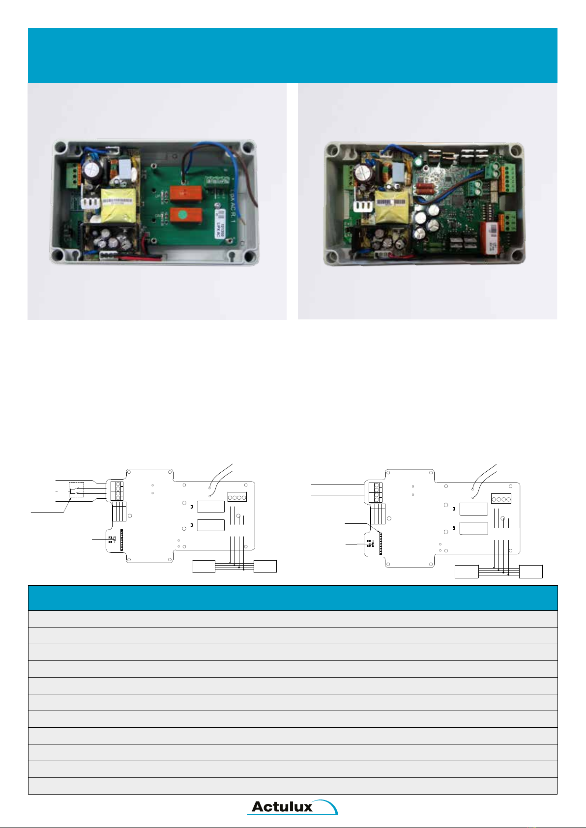
POWER SUPPLY FOR LIP OR CHAIN MOTOR
The Flex1 ACDC consists of an electrical high performance
230VAC / 24VDC Switch Mode Power Supply.
It is possible to mount LIP5, LIP6 or LIP7 from the traditional
Actulux Opening System enabling them to be supplied by
230V.
As additional it can also be used as a 230VAC supply for ex.
24VDC Chain Drives HCM / HCV or Spindle Drives.
In both options it is possible to congure the Flex1 ACDC with
a RF-receiver PCB #111894 to make remote control possible
for comfort ventilation use and for the Actulux Weather
Sensors.
www.actulux.com
Denmark
DK 9560 Hadsund
Haandvaerkervej 2
Actulux A/S Phone int.: +45 98 57 40 90
Fax int.: +45 96 15 28 00
e-mail: info@actulux.com
Power to Actulux LIP module
2
Blue
To be cut if DCR is going to be used
Sync 1
Sync 2
HTRW
Jumper
HCM
Grey
White
Blue
Red
DOWN
if mounted.
1
Neutral
Earth
Phase
UP
ON
UP
318001504230
LipX AC R. 1
1
2
HCV
HCM
without LIP
Brown
HTRW
HCV
Comfort Switch
OPUS part no. 111753
Actulux A/S
Denmark
DK 9560 Hadsund
Haandvaerkervej 2
www.actulux.com
Phone int.: +45 98 57 40 90
Fax int.: +45 96 15 28 00
e-mail: info@actulux.com
ON
1
318001504230
N NEUTRAL
2
HCV
Sync 1
UP
LipX AC R. 1
Brown
To be cut if DCR is going to be used
Mount 111894
Jumper
Blue
Blue
Sync 2
1
2
Red
Neutral
Earth
PD DOWN
HCM
White
PD
HCM
without LIP
Grey
Phase
if mounted.
PE EARTH
HTRW
Power to Actulux LIP module
HCV
HTRW
PU UP
Flex1 ACDC - AC controlled Flex1 ACDC - RF controlled
Flex1 ACDC as supply for motors with own
overload protector. (Chain & Rack Drives)
Box size (LxWxH): 180 x 110 x 63 mm
Flex1 ACDC as supply for build in
overload protector ex. LIP7 OC #121308
Box size (LxWxH): 180 x 110 x 63 mm
FEATURES
Power supply: 230VAC - max. 1.5A
Output: 24VDC
Can be used with all kinds of 24VDC motors with own overload protection
Max. operation time 120 sec. Duty cycle 10% 2 min. / 18 min.
IP class: IP66
Operating temperature: -15°C - +40°C
Product no.: #121370 3A / 65W
Product no.: #121380 4A / 80W
Product no.: #121390 6A / 150W
Product no.: #121360 8A / 200W
Option: RF control by use of #111894
Flex1 ACDC
AC Power Supply for LIP or Chain Motor
16
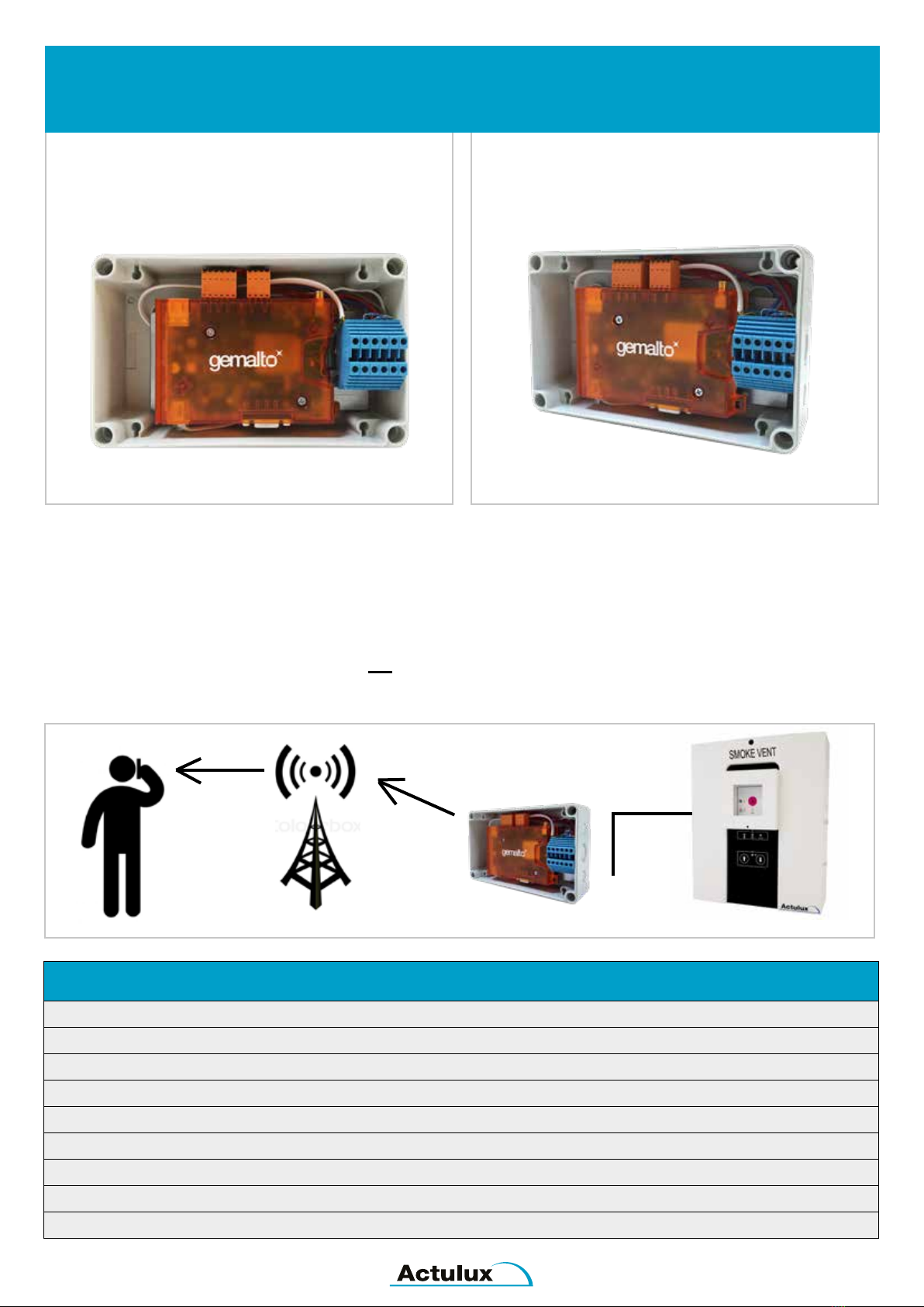
Actulux GSM Modem
Module for Control Panels
FEATURES
Power: 12V to 30VDC (300mA at 24V)
Dimensions (HxWxD): 180x110x60 mm
Weight: 0.6 kg
Protection class: IP65
Operating temperature: -10° to +45° C
CE-marking: in accordance with the EMC-directive and low voltage directive
Connection of unit has to be carried out by professionals
Product no.: #111950
Optional: Actulux battery box 12Ah - for 72 hours backup (Product no. #216000)
MODULE FOR CONTROL PANELS
Actulux GSM Modem is an advanced module for new and
existing installations.
This GSM Modem texts a pre-dened mobile no. if one of
the inputs is activated.
The unit is intended for information about e.g. an open roof
light and other relevant information. The unit is not to be
considered as an alerting system in case of re, but solely
as an information unit.
The installation is simple, as the unit only needs to be
connected to the fail- and alarm output in the control panel
as specied in the documentation.
The software in the unit can be set to any mobile no.
to receive an SMS. All you need is a computer, a USB
cable and software in order to take advantage of this
advanced unit.
GSM Modem Control panel
SMS

17
“Add on” Relay PCB
heat control, indication on BMS controls, intruder alarms
PCB FOR INDICATION OF WINDOW POSITION
This “Add on“ relay PCB can be used where indication
about opened windows on the comfort or alarm function
is needed.
The “Add on“ relay PCB is going to be connected through
a at cable to the SV control unit and the indication LED
display in the front.
FEATURES
Supply: 24V DC
Contact function: 2 pcs. NO/NC contacts
Load on contacts: 230V / 2A
LED1 / LED2: Indication about open
Can also be used for indication of active weather sensor (requires special software in control panel)
Part no.: #111690 (SV Control Panels)
Connection
18
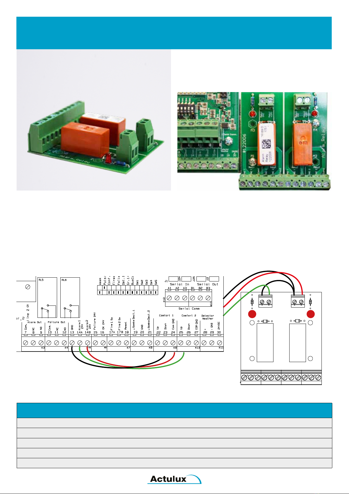
Alarm / Failure Add-on Relay PCB
extra potential free NO / NC contact for SV control panels
SV24-48 Conn. diagram extra Alarm
relay PCB 122006
Drawing: 111968
30A Green 3A Violet
ON ®
No. of
terminations
Actuator 1
Motor line monitor
Ext 3 wire monitor
FUSE F3
LD1. Aktuator 1 åben (rød). Lyser når aktuator 1 åbner.
LD2. Aktuator 1 lukke (grøn). Lyser når aktuator 1 lukker.
LD3. Aktuator 2 åben (rød). Lyser når aktuator 2 åbner.
LD4. Aktuator 2 lukke (grøn). Lyser når aktuator 2 lukker.
LD5. Vejrsensor aktiv (rød). Lyser ved aktiv vejrsensor.
LD6. Liniefejl aktuator 1 (rød). Lyser ved aktuator 1 liniefejl.
LD7. Liniefejl aktuator 2 (rød). Lyser ved aktuator 2 liniefejl.
LD8. Liniefejl brandtryk (rød). Lyser ved brandtryk liniefejl.
LD9. Liniefejl røgdetektor 1 (rød). Lyser ved røgdetektor 1 liniefejl.
LD10. Liniefejl røgdetektor 2 (rød). Lyser ved røgdetektor 2 liniefejl.
LD11. BUS fejl (rød). Lyser når lokal enhed ikke modtager BUS signal
FUSE F4
No. of
terminations
Actuator 2
Motor line monitor
Ext 3 wire monitor
Input
J29
SV XX/24A XX/32A
5A YELLOW
SV XX/8A
15A BLUE
F3+F4
fejl relæ
trukket ved
OK drift
= com+NO
er sluttet
+24V
0V
-Bat1
-PS1
+PS2
-PS2
+PS1
+Bat2
+48V 24V-Gnd
-Bat2 +Bat1
DIP NO1 2345678910111213
GND
Relay2
#122006
NO 1
NC 1
Com1
Com2
NC 2
NO 2
NO 1
NC 1
Com1
NO 2
NC 2
Com2
Relay1 Relay1 Relay2 Relay2
Alarm_Relay
Relay1
Relay1
GND
+24V
+24V
Relay2
Specifikationer
Forsyningsspænding 24VDC
Kontaktudgang: 4 x potential fri skiftekontakt
Kontaktbelastning: 230V / 2A
Led1 / Led2: Indikation af aktivt relæ
This “Add on“ relay PCB can be used when
more NO / NC contacts are needed.
Each relay has 2 potential free NO / NC contacts.
FEATURES
Supply: 24V DC
Contact function: 2 pcs. NO/NC contacts
Load on contacts: 230V / 2A
LED1 / LED2: Indication of relays ON / OFF
Part no.: 111930
SV Control panel Add-on Relay
SV24-48 Conn. diagram extra Alarm
relay PCB 122006
Drawing: 111968
30A Green 3A Violet
ON ®
No. of
terminations
Actuator 1
Motor line monitor
Ext 3 wire monitor
FUSE F3
LD1. Aktuator 1 åben (rød). Lyser når aktuator 1 åbner.
LD2. Aktuator 1 lukke (grøn). Lyser når aktuator 1 lukker.
LD3. Aktuator 2 åben (rød). Lyser når aktuator 2 åbner.
LD4. Aktuator 2 lukke (grøn). Lyser når aktuator 2 lukker.
LD5. Vejrsensor aktiv (rød). Lyser ved aktiv vejrsensor.
LD6. Liniefejl aktuator 1 (rød). Lyser ved aktuator 1 liniefejl.
LD7. Liniefejl aktuator 2 (rød). Lyser ved aktuator 2 liniefejl.
LD8. Liniefejl brandtryk (rød). Lyser ved brandtryk liniefejl.
LD9. Liniefejl røgdetektor 1 (rød). Lyser ved røgdetektor 1 liniefejl.
LD10. Liniefejl røgdetektor 2 (rød). Lyser ved røgdetektor 2 liniefejl.
LD11. BUS fejl (rød). Lyser når lokal enhed ikke modtager BUS signal
FUSE F4
No. of
terminations
Actuator 2
Motor line monitor
Ext 3 wire monitor
Input
J29
SV XX/24A XX/32A
5A YELLOW
SV XX/8A
15A BLUE
F3+F4
fejl relæ
trukket ved
OK drift
= com+NO
er sluttet
+24V
0V
-Bat1
-PS1
+PS2
-PS2
+PS1
+Bat2
+48V 24V-Gnd
-Bat2 +Bat1
DIP NO1 2345678910111213
GND
Relay2
#122006
NO 1
NC 1
Com1
Com2
NC 2
NO 2
NO 1
NC 1
Com1
NO 2
NC 2
Com2
Relay1 Relay1 Relay2 Relay2
Alarm_Relay
Relay1
Relay1
GND
+24V
+24V
Relay2
Specifikationer
Forsyningsspænding 24VDC
Kontaktudgang: 4 x potential fri skiftekontakt
Kontaktbelastning: 230V / 2A
Led1 / Led2: Indikation af aktivt relæ

19
Notes

20
06.01.2020
This manual suits for next models
20
Table of contents
Popular Accessories manuals by other brands


S+S Regeltechnik
S+S Regeltechnik Thermasgard ALTF 1 Operating Instructions, Mounting & Installation

Lennox EMEA
Lennox EMEA 3C Series installation instructions

Novalynx
Novalynx 200-WS-02 Series user manual

Agreto
Agreto XK3 user manual

Artens
Artens Kano instruction manual

MOBILE-ALERTS
MOBILE-ALERTS MA10101 quick reference

Hytronik
Hytronik HIM31 Installation and instruction manual

elero
elero Unio-868 operating instructions

GRASS VALLEY
GRASS VALLEY LDK 4582 datasheet

Byron
Byron B322 Installation and operation instruction

SENSIT Technologies
SENSIT Technologies RAMP Operation and Configuration Guide

Alnor
Alnor HRQ-PremAIR-GATE user manual