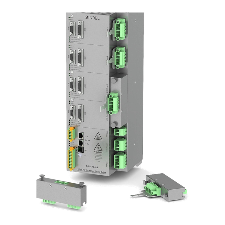
Indel SAC4 series Instructions for use

Version: Rev 1.36
Date: 04.07.2019
Language: English
Issue: Translation
Hardware
User Manual
GIN-SAC4xX


Page 3 of 90 04.07.2019Rev 1.36
Inhaltsverzeichnis
1. General 8
1.1. About this manual 8
1.2. Sales and Service 8
1.2.1. Manufacturer 8
1.2.2. Support 8
1.3. Disclaimer 8
1.4. Copyright 8
1.5. Documentation versions 9
1.6. Used terms 11
1.7. Symbols used 12
2. Safety 13
2.1. Safety instructions 13
2.1.1. Qualiedpersonnel 13
2.1.2. Documentation 13
2.1.3. ESD protection 13
2.1.4. Protection against contact with electrical components 13
2.1.5. Turno 14
2.1.6. High voltage test, insulation resistance test 14
2.1.7. Residual Current Circuit Breaker 14
2.1.8. SafeTorqueo 14
2.1.9. Maximum movement in the event of an error 14
2.2. Safety requirements 15
2.2.1. Risk analysis 15
2.2.2. Checking the safety function 15
2.2.3. Run-on 15
2.2.4. Braking resistance 15
2.2.5. Residual energy in the intermediate circuit 16
2.2.6. Safety covers 16
2.2.7. Protection against dangerous movements 16
2.2.8. Suspended loads 16
2.2.8.1. Loss of the logic power supply 17
2.2.9. Power failure of the mains supply 17
2.2.10. EMC 17
2.2.11. Commissioning 17
2.2.12. Service life 18
2.2.13. Simple protection against bypassing 18

Page 4 of 90 04.07.2019Rev 1.36
2.2.14. Responsibility 18
2.2.15. Defective drives 18
2.3. Intended use 19
3. Handling 20
3.1. Storage 20
3.2. Maintenance 20
3.3. Repair Service 20
3.4. Disposal 20
4. Productidentication 21
4.1. Scope of delivery 23
4.1.1. GIN-SAC4x4 23
4.1.2. GIN-SAC4x3 23
4.1.3. GIN-SAC4x2 24
4.1.4. GIN-SAC4x1 24
4.2. Rating plates 25
4.2.1. SAC4x4 230V 25
4.2.2. SAC4x4 400V 25
4.2.3. SAC4x3 230V 26
4.2.4. SAC4x3 400V 26
5. Stop/EmergencyPowerOfunctionsinaccordancewithEN60204 27
5.1. Emergency stop 27
5.1.1. Implementing emergency stop category 0 27
5.1.2. Implementing emergency stop category 1 28
5.2. Emergency halt 28
5.3. EmergencyPowerO 29
6. Safety functions with the SAC4 30
6.1. Safetorqueo(STO) 30
6.2. Connection example 30
6.2.1. SAC4 drives with STO 31
6.2.2. Diagnostic function in the servo drive 31
6.2.3. Monitoringofthediagnosticpath(K1-K2)bytheuser 31
7. Technical description 32
7.1. SAC4xX option PRO 32
7.2. Rotary option switch 32
7.3. Technicalspecications 33
7.3.1. General 33
7.3.2. Mains connection and intermediate circuit 33

Page 5 of 90 04.07.2019Rev 1.36
7.3.3. Nominal currents of output stages 35
7.3.4. Logic power supply 38
7.3.5. Motor 38
7.3.6. Feedback 39
7.3.6.1. SinCos 39
7.3.6.2. Resolver 39
7.3.6.3. Incremental encoder 40
7.3.6.4. Absolute value feedback 40
7.3.7. Digital IOs 41
7.3.8. Safetorqueo(STO) 42
7.4. Ambient conditions 43
8. Electrical installation 44
8.1. Notes 44
8.2. Pin assignment of SAC4xX 45
8.2.1. GIN-SAC4x4 overview 45
8.2.2. GIN-SAC4x3 overview 46
8.2.3. GIN-SAC4x2 overview 47
8.2.4. GIN-SAC4x1 overview 48
8.2.5. Logic power supply / Digital IOs 49
8.2.6. Mains connection 49
8.2.7. Motor connections 50
8.2.8. Intermediate circuit voltage 50
8.2.9. Braking resistance 51
8.2.10. Feedbacksx 51
8.2.11. STO 52
8.3. Motor connection 53
8.3.1. 3-phase motor on one output stage 53
8.3.2. 3-phase motor on two parallel output stages 53
8.3.3. DC motor at an output stage 54
8.4. Mains connection 55
8.5. Intermediate circuit 56
8.6. Logic power supply 56
8.7. Digital IOs 57
8.7.1. Inputs 57
8.7.2. Outputs 57
8.8. External brake resistance 58
8.9. Feedback 58
8.9.1. SinCo feedback 58

Page 6 of 90 04.07.2019Rev 1.36
8.9.2. Resolver feedback 59
8.9.3. Incremental encoder feedback 60
8.9.3.1. Connection to absolute value interface 60
8.9.3.2. Connection to SinCos interface 61
8.9.3.3. Connection of single-ended incremental encoder 62
8.9.4. Absolute value feedbacks 63
8.9.4.1. Hiperface 63
8.9.4.2. EnDat 2.1 64
8.9.4.3. SSI 65
8.9.5. Temperature sensors 65
8.10. Voltage supply 66
8.10.1. Logic power supply 66
8.10.2. Mains connection 66
8.11. Wiring 67
8.11.1. Conductor cross-sections SAC4x4 67
8.11.2. Routing of motor cables 67
8.11.3. Cable routing of the safety-related cut-out 67
8.11.4. Routing of SinCos, incremental, and resolver lines 68
8.11.5. Potential equalisation 68
8.11.6. Protective earth connection 68
8.12. Motor overload protection 68
8.12.1. I2t cut-out 68
8.12.2. Braking resistance 68
9. Mechanical installation 69
9.1. Notes 69
9.2. Assembly instructions 69
9.3. GIN-SAC4x4 70
9.3.1. Assembly 70
9.3.2. Dimensions 71
9.4. GIN-SAC4x3 72
9.4.1. Assembly 72
9.4.2. Dimensions 73
9.5. GIN-SAC4x2 74
9.5.1. Assembly 74
9.5.2. Dimensions 75
9.6. GIN-SAC4x1 76
9.6.1. Assembly 76

Page 7 of 90 04.07.2019Rev 1.36
9.6.2. Dimensions 77
10. Troubleshooting 78
10.1. Status LED 78
11. Further documents 81
11.1. EC Declaration of Conformity 81
11.2. TypecerticateforSAC4x4 82
11.3. TypecerticateforSAC4x3 84
11.4. TypecerticateforSAC4x2 86
11.5. TypecerticateforSAC4x1 88
12. Standards 90

Page 8 of 90 04.07.2019Rev 1.36
General
1. General
1.1. About this manual
This user manual describes the Indel servo drives of the SAC4 series. This document is the original
edition.
1.2. Sales and Service
1.2.1. Manufacturer
Indel AG
Tüwis 26
CH-8332 Russikon
Switzerland
www.indel.ch
Tel.: +41 44 956 20 00
Fax: +41 44 956 20 09
1.2.2. Support
Indel AG provides you with extensive technical support:
• Engineering for hardware and soware
• Worldwide support via Team Viewer
• Worldwide on-site technical support
• Commissioning of controls and drives on site
1.3. Disclaimer
The documentation was created to the best of our knowledge and belief. However, the products de-
scribed are constantly being developed and improved. The documentation should therefore never be
considered complete. All information in the documentation is without guarantee. We reserve the right
to make changes at any time without notice. No claims can be made regarding changes to products
which have already been delivered.
1.4. Copyright
© Indel AG
Unless specically authorised by Indel, the redistribution and reproduction of this document is pro-
hibited.

Page 9 of 90 04.07.2019Rev 1.36
General
1.5. Documentation versions
Version Date Author Comment
Rev pr M. Suter All dra versions issued before the rst release.
Rev 1.00 26.02.2014 M. Suter • Release
Rev 1.10 19.05.2014 M. Suter • Incorporation of the GIN-SAC4x3
Rev 1.11 20.05.2014 M. Suter • Addition of assembly instructions, rotary option
switch and rotary switch description
Rev 1.12 13.06.2014 M. Suter • Correction GIN-SAC4x3 only 3x output stage
Rev 1.20 09.07.2014 M. Suter • Chapter 6.1 deleted
• Issue: Original added to cover page
• Chapter 2.3 not to be used in explosion hazard
areas
• Chapter 2.3 Only for use in industrial contexts
• Chapter 2.1.1 extended
• Chapter 2.2.2 added
• Chapter 7.3.8, fuse protection of the relay 1A
• Chapters 5.1.1 and 5.1.2 for illustrative purposes
only
Rev 1.21 28.07.2014 M. Suter • Change to interactive PDF format
Rev 1.22 06.08.2014 M. Suter • Various corrections
• Standards updated
Rev 1.23 11.08.2014 M. Suter • Adaptations to EMC standard
Rev 1.24 12.08.2014 M. Suter • Declaration of Conformity added
Rev 1.25 11.11.2014 M. Suter • Chapter 7.3.4, Power consumption of
logic power supply < 2A
Rev 1.26 25.11.2014 M. Suter • Type certicate for SAC4x4 and SAC4x3 added
Rev 1.27 02.04.2015 M. Suter • Status LED chapter 10.1 on page 78 added
Rev 1.28 02.04.2015 M. Suter • Reaction time tOFF of the STO in chapter 7.3.8 on page 42
corrected from 3ms to 15ms
Rev 1.29 15.04.2015 M. Suter • Modication to conductor cross-sections chapter
8.11.1
• Modication to motor overload protection chapter
8.12
• Modication to assembly instructions chapter 9.2
Rev 1.30 31.07.2015 M. Suter • Suva approval on rating plates
• Incorporation GIN-SAC4x1
• Various corrections
Rev 1.31 28.10.2015 M. Suter • PT100 and PT1000 can now also usable as tempera-
ture sensors, chapter 8.9.5
Rev. 1.32 19.04.2016 M. Bleuler • Declaration of Conformity adjusted according to
current guidelines, chapter 11.1
• Intermediate circuit capacity added for SAC4x3,
SAC4x2 and SAC4x1, chapter 7.3.2
Rev. 1.33 17.10.2016 M. Bleuler • D-Sub mating connector corrected in chapters 4.1.1,
4.1.2, 4.1.3 and 4.1.4
• GIN-SAC4x2 in chapter 4, chapter 4.1.3, chapter
6.2.1, chapter 7.3.1, chapter 7.3.3, chapter 8.2.3 and
chapter 9.5 added
• Type-examination certicate GIN-SAC4x2 and GIN-
SAC4x1 added in chapters 11.4 and 11.5

Page 10 of 90 04.07.2019Rev 1.36
General
Rev. 1.34 13.12.2016 M. Bleuler • New sketch added under assembly instructions in
chapter 9.2
• EC Declaration of Conformity adapted only for STO
option in chapter 11.1
Rev. 1.35 15.06.2017 M. Bleuler • Old Indel logo replaced with new Indel logo
• Relinking the URLs
Rev. 1.36 06.02.2018 M. Bleuler • Former Chapter 8.3.3 "three parallel ouput stages"
deleted, as not implemented to date.
• Additional note added under chapter 6.2.2 in con-
nection with internal evaluation.
• Chapter 6.2.3 added for better understanding in
conjunction with Chapter 6.1.
• Overvoltage category standard in chapter 7.3.2
adjusted.
• Overvoltage category standard in chapter7.4 ad-
justed.
• Pin assignment of positions in image in chapters
8.2.2 and 8.2.3 corrected.

Page 11 of 90 04.07.2019Rev 1.36
General
1.6. Used terms
Abbreviation Meaning
GinLink Indel Fieldbus, 1GBit/s Ethernet based
PE conductor Earth conductor
GIN-SAC4xX Designation for entire GIN-SAC4 series
GIN-SAC4 Designation for entire GIN-SAC4 series
GIN-SAC4x4 Designation for GIN-SAC4 with 4 output stages
GIN-SAC4x3 Designation for GIN-SAC4 with 3 output stages
GIN-SAC4x2 Designation for GIN-SAC4 with 2 output stages
GIN-SAC4x1 Designation for GIN-SAC4 with 1 output stage
+DC / -DC- Intermediate circuit tapped onto the servo drives
Fieldbus master Master of the GinLink eldbus

Page 12 of 90 04.07.2019Rev 1.36
General
1.7. Symbols used
Important notice for the user
The symbol indicates important information for the user. All instructions must be ob-
served
ATTENTION
Attention
The symbol indicates information which, if not observed, could lead to damage to prop-
erty and/or personal injury.
DANGER
Danger
This symbol indicates information which, if not observed, could result in personal injury
caused by electricity
WWW. Hyperlink
Indicates a hyperlink to a le or information on the Internet
Reference
Reference to a chapter within the documentation

Page 13 of 90 04.07.2019Rev 1.36
Safety
2. Safety
2.1. Safety instructions
The following safety instructions male no claim to completeness. If you have any questions, uncertain-
ties or problems, please contact us.
2.1.1. Qualiedpersonnel
All work such as transport, installation, commissioning and service may only be carried out by quali-
ed specialist personnel. Qualied specialist personnel are persons who are familiar with the trans-
port, installation, assembly, commissioning and operation of the product and who have the qualica-
tions required for their job. National accident prevention regulations must be observed. The safety
instructions, the information on the connection conditions (rating plate and documentation) and the
limit values specied in the technical data must be read carefully before installation and commission-
ing and must be strictly adhered to.
2.1.2. Documentation
Before installation and commissioning, please read this documentation as well as the documentation
which is referenced in their entirety. Incorrect handling can lead to personal injury or damage to prop-
erty. Be sure to comply with the technical specications, connection conditions and environmental
conditions.
2.1.3. ESD protection
The servo ampliers contain electrostatically sensitive components that can be damaged by improper
handling. Discharge the static your body before touching the servo ampliers.
Avoid contact with highly insulating materials (synthetic bers, plastic lms etc.). Place the servo am-
pliers on a conductive surface in a voltage-free state. Do not touch the contacts of the connector on
the drive and the connected cables or the contact pins on the conductors.
2.1.4. Protection against contact with electrical components
For the operation of the servo amplier it is necessary that certain parts carry voltages of more than
50VAC, i..e extra-low voltages. If such parts are touched, life-threatening electric shocks may occur.
There is a risk of death or serious damage to health.
Before switching on a drive, make sure that the device is properly connected to the PE conductor. The
earth connection must always be connected, even if the drive is only put into operation for a short
time.
Before switching on, live parts with more than 50VAC must be protected against direct contact by
means of suitable measures.
Connections can also carry dangerous voltages when the motor is not turning. Touching the terminals
when they are switched on is therefore prohibited.
Before working on the drive, disconnect it from the mains and secure it against being switched on
again.
Contact with live parts (e.g. terminals) may result in death or serious health or material damage.
Never disconnect the electrical connections of the modules whilst live. In unfavorable cases, arcing
can occur, harming people and hardware such as contacts.
DANGER

Page 14 of 90 04.07.2019Rev 1.36
Safety
2.1.5. Turno
Aer switching o the mains supply, residual voltages can be present for several minutes. Measure the
intermediate circuit voltage and wait until the voltage has fallen below 50V.
2.1.6. High voltage test, insulation resistance test
Do not perform a high voltage test or an insulation resistance test on the mains connection and motor
connection of the drives, otherwise the drive will be destroyed.
2.1.7. Residual Current Circuit Breaker
Only type B universal current-sensitive Residual Current Circuit Breakers may be used.
2.1.8. SafeTorqueo
The safety function STO as described in chapter 6 is designed as a safety pulse inhibitor. The drive may
restart aer resetting the pulse inhibitor, depending on the application.
Activating the safety function is not suitable for de-energising the drive. Activating the safety function
does not provide protection against electric shock.
2.1.9. Maximum movement in the event of an error
It should be noted that a multiple fault in the IGBT bridge could cause th motor to advance for a short
period. The maximum rotational angle of the motor sha occurring when advancing depends on the
number of pole pairs in the motor used.
For permanently activated servo motors:
ϕ=360◦
2
·
pϕ=angle of ratation;p=pole pairs
d=P
2d=linear movement;P=pole pitch
1
For linear motors:
ϕ=360◦
2·pϕ=angle of ratation;p=pole pairs
d=P
2d=linear movement;P=pole pitch
1
DANGER

Page 15 of 90 04.07.2019Rev 1.36
Safety
2.2. Safety requirements
During the installation and operation of Indel Drives in applications with stop category 0 or 1 safety-
related cut-out of the drive according to EN 60204-1 and fail-safe protection against restart in accor-
dance with EN ISO 13849-1 cat. 3 / PL d, all conditions apply Manual and conditions that are referred to
compulsory.
Indel servo drives with the STO function have been developed according to the relevant standards. A
certication or a type examination is currently in progress.
2.2.1. Risk analysis
The machine manufacturer must prepare a risk analysis for the machine and take appropriate mea-
sures so that unforeseen movements do not lead to damage to persons or property.
There are also indications in this document regarding possible dangers. All information on dangers,
warnings, precautionary measures and information must be observed.
2.2.2. Checking the safety function
The safety function according to EN ISO 13849-1 with a Performance Level e must be checked at least
once a month during continuous operation.
The safety function according to EN ISO 13849-1 with a performance level d must be checked at least
once a year during continuous operation.
2.2.3. Run-on
If application-dependent dangers arise as a result of the run-on, additional protective measures must
be taken (e.g. movable guards with locks), in order to cover the danger area until there is no danger to
persons or property.
It must be taken into account that, without a mechanical brake or with a defective brake, drive run-on
is possible.
2.2.4. Braking resistance
The braking resistor is not safely controlled by the Indel servo drives. A defective or improperly con-
nected braking resistor will cause the motor to stop outside the expected timespan. In the worst case,
this can lead to personal injury and damage to property.

Page 16 of 90 04.07.2019Rev 1.36
Safety
2.2.5. Residual energy in the intermediate circuit
Residual charge in the intermediate circuit capacitors can be retained for up to 10 minutes aer
switching o the power supply (opening the main contactor or motor contactor). It is possible to move
the motor with this residual charge. This can potentially lead to dangerous situations. If additional
external capacitor modules are used, it will take longer for the intermediate circuit capacitors to dis-
charge.
The following warning is attached to the drives.
2.2.6. Safety covers
Additional safety covers must be designed and integrated in accordance with the safety category
required for the machine according to EN ISO 13849-1. Aer the stop command has been triggered, de-
pending on the danger posed, access must remain locked until the drive has come to a complete stop.
2.2.7. Protection against dangerous movements
Incorrect activation of motors can trigger unintended and dangerous movements.
• Incorrect installation
• Faulty design
• Faulty or incomplete wiring
• Defective devices or cables
• Incorrect control by the soware
As a rule, aer switching on the drive, motor movement is to be expected. Protection of persons and
machines can only be guaranteed by means of overarching measures. Suitable measures are to be
taken in order to protect the range of motion of machinery against unintentional access by people.
Removing, bridging, or bypassing safety devices is strictly prohibited. A suicient number of easily ac-
cessible Emergency Power O switches is to be attached to the machine. Keep all covers and cabinet
doors closed during operation.
2.2.8. Suspended loads
In the case of suspended loads, addition measures must be taken in order to ensure that the axis stays
in place. The Indel servo drives do not oer any outputs which allow you to safely control securing
brakes. Holding brakes provide no protection when slowing down the motor.
GIN-SAC4x4_Front
GEWICHT:
A1
BLATT 1 VON 1
MASSSTAB:1:1
ZEICHNUNGSNR.
BENENNUNG:
ÄNDERUNG
ZEICHNUNG NICHT SKALIEREN
WERKSTOFF:
DATUM
SIGNATUR
NAME
ENTGRATEN
UND SCHARFE
KANTEN
BRECHEN
OBERFLÄCHENGÜTE:
WENN NICHT ANDERS DEFINIERT:
BEMASSUNGEN SIND IN MILLIMETER
OBERFLÄCHENBESCHAFFENHEIT:
TOLERANZEN:
LINEAR:
WINKEL:
QUALITÄT
PRODUKTION
GENEHMIGT
GEPRÜFT
GEZEICHNET
Caution!
Hazardous
voltage remains
for 10 minutes
after removing
main power
supply.
X10 Motor 0 X11 Motor 1 X12 Motor 2 X13 Motor 3X17 Line X16 Ballast X15 Ucc
SIO
GIN-SAC4x4
Active
Motor
IMAX / IGBT
PWM / Commutation
Resolver / SinCos
GinLink
X3B
X3A
X2B
X2A
X1B
X1A
X0B
X0A
Active
Active
Active
Motor
UCC
Ballast
Control
Ext Enable
OK
Err
Folie für
Gehäuse
860128T01
SAC4x4-OT
S1
X7X100 Safety
X9 In
X8 Out
IMAX / IGBT
IMAX / IGBT
IMAX / IGBT
Motor
Motor
PWM / Commutation
PWM / Commutation
PWM / Commutation
Resolver / SinCos
Resolver / SinCos
Resolver / SinCos
High Performance Servo Drive

Page 17 of 90 04.07.2019Rev 1.36
Safety
2.2.8.1. Loss of the logic power supply
If the 24V logic power supply fails on the drive, the motor may spin out. If this is not permitted, exter-
nal measures must be taken to prevent the axis from spinning out.
2.2.9. Power failure of the mains supply
In the event of a power failure of the mains supply or the supply for the motors, the motor may spin
out. If the intermediate circuit voltage Ucc drops below the congured limit Ucc MIN, the servo drive will
fail and the motors will be disconnected from the power supply.
2.2.10. EMC
For EMC-compliant wiring, see further document INDEL Wiring Guidelines and INDEL installation
Guideline and all wiring instructions in this document.
INDEL Wiring Guiedelines
INDEL Installation Guideline (only available in German)
INDEL Wiring GuidelineINDEL Construction GuidelineThe machine or system manufacturer must take
additional measures for EMC protection if the product standard contains lower limit values applicable
to the machine in question. In the case of machines which contain many Indel servo drives, additional
EMC protection measures may also be required.
The controller is intended for use in industrial contexts. The regulator must be preceded by a lter at
the mains connection. See also chapter 8.10.2
In a residential environment (rst environment), this product may cause high frequency interference,
which may require further suppression measures.
2.2.11. Commissioning
Before switching on a servo drive, make sure that the device is properly connected to earth. The earth
connections must always be provided, even if the drive is only put into operation for experimental
purposes.
Control and power connections can carry voltage even when the motor is not moving. Touching the
terminals when the power is on is prohibited. Before working on the drives, they must be disconnect-
ed from the mains and secured against being switched on again.
Documented commissioning and demonstration of the safety functions must take place. For Indel
servo drive applications with stop category 0 or 1 safety-related cut-out of the drive according to EN
60204-1 and fail-safe protection against restart in accordance with EN ISO 13849 cat. 3, commissioning
of the cut-out mechanism and the correct wiring must always be carried out and recorded.
During commissioning, signal detection must be included in the functional test. The status of the aux-
iliary contacts of the safety relays can be viewed in the actual parameters in the servo drive. However,
this display is not safety-related.
WWW.
WWW.
DANGER

Page 18 of 90 04.07.2019Rev 1.36
Safety
2.2.12. Service life
Fieen years aer delivery at the latest, the safety module in the servo drives must be replaced. If used
for more than 15 years, safe operation is no longer guaranteed. This applies not only to the operating
time, but also to standstill and storage time.
2.2.13. Simple protection against bypassing
Measures must be taken to prevent bypassing of the safety functions in accordance with EN ISO 13849-
1 Cat.3 / PL d.
2.2.14. Responsibility
The servo drives are not completely fail-safe. In the event of a failure, the operator is responsible for
ensuring that the machine / system is put into a safe condition.
All of the diagnostic and monitoring functions can only interrupt the control of the motor. As a conse-
quence of this, the motor is de-energised and can no longer be controlled and braked. Depending on
the application, additional measures may be required to slow down or stop the motor.
The operator is responsible for safety.
2.2.15. Defective drives
Defective and damaged drives must under no circumstances be taken into operation. This can lead to
serious personal injury and property damage.
ATTENTION

Page 19 of 90 04.07.2019Rev 1.36
Safety
2.3. Intended use
• IndelServoDrivesmayonlybeusedasspeciedinthisdocumentandinthedocumentsto
which reference is made.
• The intended use is prohibited until it has been established that the machine complies
with the provisions of Machinery Directive 2006/42/EC and the EMC Directive 2004/108/
EEC, or the relevant current version of said directives. Otherwise, the Indel servo drives
cannot be placed on the market.
• Indel Servo Drives must only be used in industrial contexts.
• The servo drives are designed for installation in stationary electrical machines/systems
that comply with the Machinery Directive, Low Voltage Directive and the EMC Directive.
• Indel Servo Drives must be installed in a control cabinet that can only be opened using a
tool. The drives must be installed so that no live parts can be touched.
• It is imperative that the environmental conditions listed on page 43 in chapter 7.4 be
observed. Ventilation or cooling measures may be necessary to keep the cabinet tempera-
ture below 40° C.
• The GIN-SAC4 servo drives can be used directly in three-phase, earthed industrial net-
works(TNnetwork,TTnetworkwithearthedstarpointat400V+10%).Theservodrives
must not be operated on unearthed networks, nor on asymmetrically earthed networks.
• The machine manufacturer is obliged to carry out a risk analysis of the machine and to
take appropriate measures to prevent unforeseen movements from causing damage to
persons or property.
• The drives must not be used in an explosion hazard areas.

Page 20 of 90 04.07.2019Rev 1.36
Handling
3. Handling
3.1. Storage
The Indel SAC4 Drives can be stored for up to 12 months without restrictions. If the drive is stored for
more than 12 months, the capacitors must be reformed before commissioning. For this purpose, all
electrical connections must be disconnected and fed to L1 / L2 for 20min 230VAC.
3.2. Maintenance
Do not immerse or spray the housing when cleaning. If contamination is present inside the unit: Clean-
ing by the manufacturer.
3.3. Repair Service
Repairs to the servo drives must be made by the manufacturer. Indel control components can be
returned to Indel for repair. Following repair, the conguration les required for operation are deleted
from the drive.
In all cases, opening the housing of Indel servo drives will void the warranty.
3.4. Disposal
The servo drives are made of the following materials:
• Steel housing
• Aluminum heat sink
• Electronic circuit boards
The individual components must be disposed of properly. All servo drives can be returned to Indel AG
for proper disposal. The costs of transport are borne by the sender.
This manual suits for next models
5
Table of contents
Other Indel Servo Drive manuals
Popular Servo Drive manuals by other brands
Mannesmann Rexroth
Mannesmann Rexroth Indramat DDC Series Applications manual
DMM
DMM DYN 5 Series instruction manual
LinMot
LinMot E14 0 V2 Series installation guide
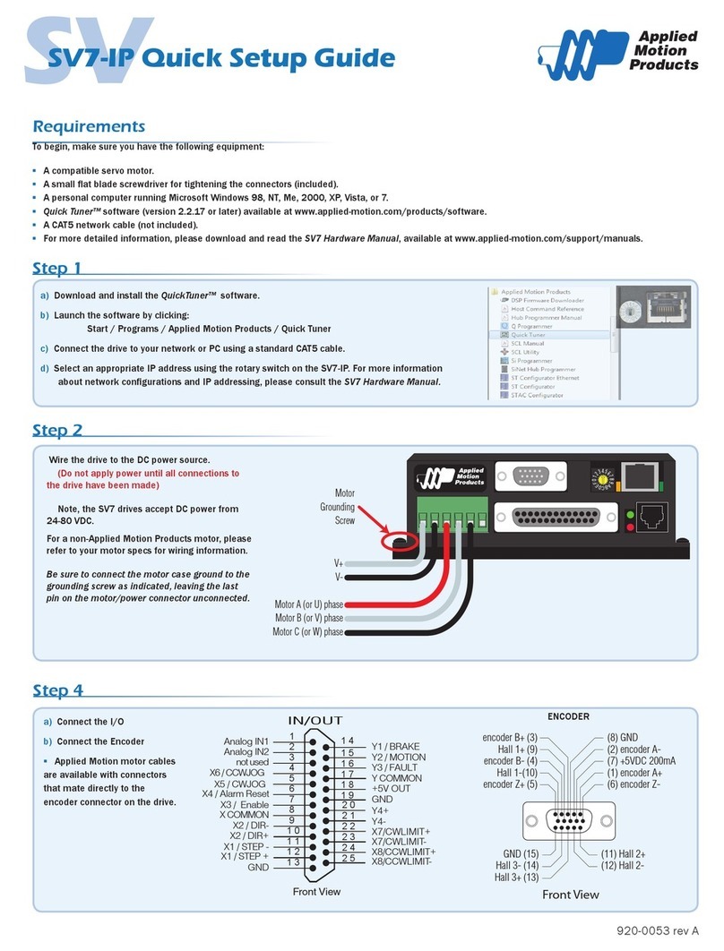
Applied Motion Products
Applied Motion Products SV7-IP Quick setup guide
Moons'
Moons' SSM24C user manual
Beckhoff
Beckhoff AX8-1 Series Documentation
