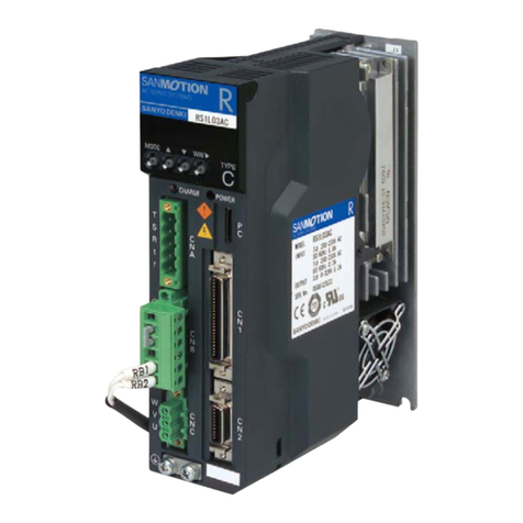
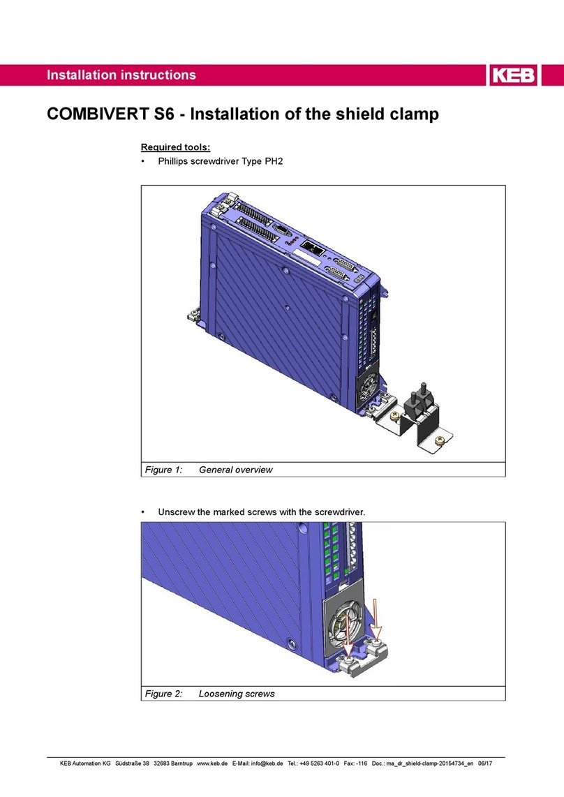
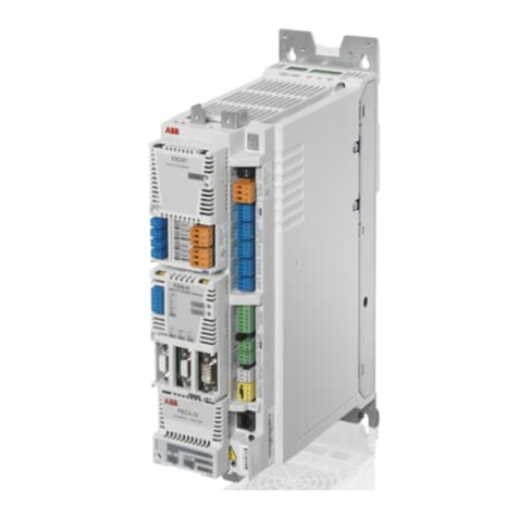
Moog DS2020 Mounting instructions

DS2020
MAINTENANCE AND USER MANUAL
SINGLE AXIS DIGITAL SERVO DRIVE
INDEX
1. OVERVIEW 5
5
5
5
6
1.1. Manual contents
1.2. Utilized symbols
1.3. Package content
1.4. Required qualifications of the users
1.5. Applicable laws 6
2. SYSTEM DESCRIPTION 7
7
9
9
10
10
11
11
12
14
14
15
20
21
21
21
2.1. Product structure
2.1.1. Product description
2.1.2. Storage and working conditions
2.1.3. Standard models of modules
2.1.4. Module codification
2.2 Features and components details
2.2.1 Electrical data
2.2.2 Mechanical data
2.2.3 Trasducers
2.2.4 Connectors
2.2.4.1 Connectors layout
2.2.5 Filters
2.2.6 Braking resistence
2.2.7 Line inductors
2.3 Cables
2.4. Safety and usage guidelines 22
DS2020
L-MAS2-E-161

2.4.1. General description of security features
22
2.4.2. STO safety feature
22
2.4.2.1. Description
22
2.4.2.2. Directives on safety
23
2.4.3. Usage Guidelines of the drivers
23
3.CERTIFICATIONS25
25
3.1. CE
3.2. Safety and SafeTorque Off
26
4. ELECTRICAL AND MECHANICAL INSTALLATION 27
27
27
27
28
28
29
30
30
30
31
31
32
32
33
33
33
33
34
34
34
34
36
36
37
4.1 Tools and equipment
4.2. Mechanical installation
4.2.1. Assembly of the various components
4.3. Electrical Installation and thermal rating
4.3.1 Safety and general instructions
4.3.2. Thermal rating of the electrical panel
4.3.2.1. Drive axis module dissipation
4.3.2.2. Thermal dissipation of the accessories
4.3.3. Auxiliary power characteristics
4.3.4. Grid connection
4.3.4.1. Types of electrical networks
4.3.4.2. Protection components
4.3.4.3. Ground connection
4.3.5. Drive wiring
4.3.5.1. Grounding
4.3.5.2. Connecting the Power cable
4.3.5.3. Braking resistor connection
4.3.5.4. Auxiliary power connection
4.3.5.5. Signal connection
4.3.5.6. Motor cable connection
4.3.5.7. Brake cable connection
4.3.5.8. I / O signal connection
4.3.5.9. STO signal connection
4.3.5.10. Transducer connection
4.3.5.11. Connecting the Fieldbus - X8, X9, X10 connectors
38
5. COMMISSIONING VIA GUI 39
39
40
40
40
41
42
5.1. Safety
5.2. Dx2020 GUI
5.2.1. Overview
5.2.2. Minimum PC requirements
5.2.3 Dx2020GUI installation
5.2.4 GUI-drive connection
5.2.5 Layout
43
DS2020
L-MAS2-E-161
2

5.2.6. Firmware update (BootLoader) 45
5.2.7. How to access to Online Help
45
5.3. System configuration 45
5.3.1. Identifying an axis module 46
5.3.2. Motor parameters configuration 46
5.3.3. Trasducers configuration
47
5.3.3.1. Sensorless
47
5.3.4. I/O configuration
48
5.3.5. Control loops configuration
51
5.3.5.1 Control mode configuration
51
5.3.5.2 Torque loop parameters configuration
51
5.3.5.3 Speed loop parameters configuration
51
5.3.5.3.1 Filter configuration
52
5.3.5.4 Configuration of the position loop parameters
53
5.3.6. Fault configuration
54
5.3.7. Application parameters
55
5.3.8. Commands and modes configuration
56
5.4. Power Supply
58
5.5 STOactivation
58
5.5.1 Autophasing
59
5.6 Axis enablement
59
5.7. Oscilloscope function and log files (*.UCX)
60
5.7.1 Log configuration
60
5.7.2 Start logging
60
5.7.3 View logs
61
5.7.4 UCX file management
61
5.8 Using the GUI in OFFLINE mode
62
5.9 Contextual help menus for parameter management
62
6. TROUBLESHOOTING 63
63
63
63
64
65
66
66
66
66
66
67
67
68
6.1. Introduction
6.2. Power section anomalies
6.3. Drive anomalies
6.3.1. Alarms on the power section
6.3.2. Alarm for out of tolerance VBUS voltage
6.3.3. Drive or motor overtemperature
6.3.4. Removal of STO signal
6.3.5. Errors on memory devices
6.3.6. Corrupted Data Fault
6.3.7. Brake Chopper Fault
6.3.8. Errors on feedback devices
6.3.9. Synchronization, Interrupt Time and Task Time Error
6.3.10. EtherCAT Faults
6.3.11. Alarms related to the control loops
68
DS2020
L-MAS2-E-161
3

6.3.12. CAN Bus alarms
68
6.4. Alarm display in 'Analog' operating mode
69
6.5. Faults during the GUI-drive connection
72
7. SAFE TORQUE OFF SAFETY FEATURE 73
73
73
74
74
75
75
76
76
78
80
80
80
81
81
7.1. Application
7.2. Installation risk assessment
7.3. Safe Torque Off
7.3.1. Characteristic values according to UNI ENISO 13849-1
7.3.2. Characteristic values according to CEI EN62061
7.4. Safety requirements
7.5. Safe Torque Off circuit
7.6. Safe Torque Off connections
7.7. Example of an application
7.8. Installation and maintenance procedure Safe Torqueo
Off 7.9. Assembly and serial tests
7.10. Identification of the STO function on the plate
8 Annexes
8.1 Glossary
8.2 Conversion Table Metric / AWG 84
DS2020
L-MAS2-E-161
4

1. OVERVIEW
1.1. Manual contents
This manual provides information to the user to ensure proper installation and optimal functioning of the
digital servo drives, DS2020 series.
All information contained herein, including methods, techniques and concepts are the exclusive property
of Moog Casella and may be neither copied nor used without specific authorization. Moog reserves the
right to modify products, and related documentation, at any time, without notice.
The following materials are also available:
•QUICK GUIDE - INSTRUCTIONS AND GUIDELINES FOR FIRST START
•MAINTENANCE AND USER MANUAL (this document)
•FIELDBUS MANUAL
•SOFTWARE Dx2020 GUI
1.2. Utilized symbols
Danger that can result in death or serious injury
Notification of an important information
Danger that can result in minor injury and / or property damage
1.3. Package contents
The complete supply of DS2020 drives includes:
•One DS2020 drive module
•Anchoring support for the screens
Note: a possible connector kits must be ordered
individually and is supplied separately.
DS2020
L-MAS2-E-161
5

1.4. Required qualifications of the users
This manual is intended for qualified personnel, that is having the following skills, depending on the tasks performed:
Transport: The staff must have notions of handling components sensitive to electrostatic charges
Unpacking: The staff must have knowledge of handling of components sensitive to shock and electrostatic discharge
Installation: The staff must have notions of installation of electrical equipment
Startup: The staff must have extensive technical knowledge of electrical drives and their technology.
Info
The qualified personnel must know and observe the following standards: IEC 60364, IEC
60664, and all relevant national accident prevention regulations.
ATTENTION
When the drive is in operation there is a risk of death, serious injury or serious damage to property.
Therefore, the installer is required to ensure that the safety instructions detailed in this manual are read,
understood and observed by all personnel responsible for the operation of the drive.
1.5. Applicable laws
The DS2020 drives meet the Low Voltage Directive (2006/95 / EC) and EMC Directive (2004/108 / EC).
The safety function "Safe Torque Off" (STO) integrated in the drive complies with the Machinery Directive
(2006/42 / EC).
To comply with the European Directives, the drive meets the requirements of the relevant harmonized
installation standards EN 50178 (LVD), EN61800-3 (EMC) and EN 61800-5-2 (Safety of machinery).
The DS2020 drives are CE certified.
DS2020
L-MAS2-E-161
6

2. SYSTEM OVERVIEW
2.1. Product structure
2.1.1. Product description
The DS2020 drive represents Moog Casella's new generation of digital servo drives for the control of brushless
synchronous or asynchronous motors. It is constituted by a single stand alone module powered directly by an
AC network and by an auxiliary voltage of 24 Vdc
The digital control system of the motors and the diagnosis functions of the DS2020 series, are realized using a
microprocessor.
DS2020
L-MAS2-E-161
7

Control functions Implementation of the Torque, Speed and Position loops
Command protocols EtherCAT, CANopen and “Analog”
Configuration/
Commissioning
Via GUI : Dx2020GUI, allows to configure, calibrate and
control the drive.
Diagnostic Via GUI
Positioning transducers • Resolver standard
• Encoder Incremental TTL
• Encoder Stegmann Sinusoidal Absolute Single/Multi-Turn with
HYPERFACE communication
• Encoder Hedenhain Sinusoidal Absolute Single/Multi-Turn with
ENDAT communication
Sensorless mode
User Interface
Dx2020GUI
Data logging
From GUI
AC/DC conversion Three-phase input bridge with soft start
Power range From 120 Vac to 480 Vac +/- 10 %
PWM frequency 8 kHz (from 2 to 16 kHz configurable by Software)
Encoder simulation Simulated encoder output with programmable number of pulses
Auxiliary power supply voltage
+ 24 Vac +/- 10 %
Rated current From 2 to 48 Arms
Peak current From 4 to 96 Arms
Analog inputs 2 inputs +/- 10 volt differential
Analog outputs 2 output +/- 10 volt single ended
Digital inputs 2 digital inputs opto isolated
Digital outputs 1 Digital output opto isolated
Communication interface for
set-up
• RS422 PC
• USB PC
• EtherNET or CANopen PC (option)
Motor brake control Integrated
Braking resistor Integrated (Esternal optional)
Electromagnetic compatibility EMC filters
Cooling
Forced air, with integrated fans in each module
DS2020
L-MAS2-E-161
8

2.1.2. Storage and working conditions
Operating environment
temperature
from 0 °C to 40 °C
up to55 °C with current derating
Storage temperature
from -25 °C to 55 °C
Transport temperature
from -25 °C to 70 °C
Motor overheating protection PTC or NTC
Relative humidity
5...95 %
without condensation
Mounting altitude
Up to 1000 m, up to 2000 m with output current derating
Certification
CE
Protection
IP20
Pollution rating
Resistenza meccanica
conforme a EN 60721-3-3
Vibration: 3 mm for frequencies between 2 and 9 Hz
Vibration: 1 g for frequencies between 9 and 200 Hz
Shock: 98 m/s2 (10 g) for 11 ms
Machine safety
STO (Safe Torque Off) SIL3 PLe
2.1.3. Standard models of modules
L50A L50A L75A L75A L75B
Dimensions [mm]
50 50 75 75 75
Rated current [Arms]
2 4 6 8 12
Peak current [Arms] 4
8 12 16 22
The module code is found on a plate on the side of the module.
To request any kind of information about a specific module it is essential to communicate to Moog Casella all the
data indicated on the plate, which identifies each individual module.
The year and week of construction are identified by the field 'Date' The first two digits of the number are for the year
the second two indicate the week (example DATE 1607: 2016, week 7).
L85A L85A L125A L125A
85 85 125 125
16 24 32 48
32 48 64 96
Example of a drive plate
Model code
Rated data
STO function
Date
Serial Number
Moog Italiana S.r.l. - CASELLA SITE - Via Avosso 94, 16015 Casella (GE) - Italy
2 or less (normally allowed only non-conductive pollution. However, occasionally we
can expect a temporary conductivity caused by the condensation only when the drive
is idle or powered)
DS2020
L-MAS2-E-161
9

2.1.4 Module codification
To identify the different models it is necessary to refer to the following codification
The first two characters are "CH" and are used to identify the DS2020 family
Version
1Standard model
ESpecial model
Mechanical configuration - Hardware
ValueType /
Width
Rated
Current
Peak
Current
02 Single / 50 mm
L50A 2 Arms 4 Arms
04 Single / 50 mm
L50A 4 Arms 8 Arms
06 Single / 75 mm
L75A 6 Arms 12 Arms
08 Single / 75 mm
L75A 8 Arms 16 Arms
12 Single / 75 mm
L75B 12 Arms 22 Arms
(1) Standard version
(2) Values attributed by Moog
X2 / X3 - Transducer type and Serial link type
RS422
ValueType
R (1)RESOLVER SERIAL
TRESOLVER USB
EENCODER SINCOS SERIAL
UENCODER SINCOS USB
G TTL SINGLE ENDED SERIAL
HTTL FULL DIFFERENTIAL SERIAL
L TTL SINGLE ENDED USB
MTTL FULL DIFFERENTIAL USB
Fieldbus configuration
ValueType
0Analog references (1)
1 CanBus configuration
(option)
2 EtherCAT configuration
(option)
Hardware Revision
Value - Internal coding (2)
Special configurations
00 Standard
Special variation
Value - Internal coding (2)
CH-
To order a connector kit
Connector kit code Transducer type and Serial link type
BC8901-R RESOLVER SERIAL
RESOLVER USB
BC8902-R
ENCODER SINCOS SERIAL
ENCODER SINCOS USB
TTL SINGLE ENDED SERIAL
TTL FULL DIFFERENTIAL SERIAL
TTL SINGLE ENDED USB
TTL FULL DIFFERENTIAL USB
16 Single / 85mm
L85A16 Arms 32 Arms
24 Single /85mm
L85A 24 Arms 48 Arms
32 Single / 125mm
L125A 32 Arms 64 Arms
48 Single / 125mm
L125A48 Arms 96 Arms
Value - Internal coding (2)
DS2020
L-MAS2-E-161
10

2.2. Features and components details
2.2.1. Electrical data
Electrical data
L50A L75A – L75B
Network power
supply voltage From 120 Vac to 480 Vac +/- 10 %
Auxiliary voltage
24 Vdc +/-10%
Rated currentArms from 2 to 4 from 6 to 12
Peak current Arms from 4 to 8 from 12 to 22
Protections
Cooling
Forced air, with built-in fans
L85A L125A
Protection with thermal reading of the heat sink temperature and estimation of the
temperature of the power module junction. Insufficient voltage (Under Voltage) or
excessive voltage (over voltage) detection
DS2020
L-MAS2-E-161
11
from 16 to 24
from 32 to 48
from 32 to 48
from 64 to 96

7.5 (0.30)
4.5 (0.18)
180 (7.09)
199.40 (7.85)
50 (1.97)
203 (7.99)
215 (8.46)
170 (6.69)
21 (0.83)
7.5 (0.30)
4.5 (0.18)
180 (7.09)
199.40 (7.85)
75 (2.95)
203 (7.99)
215 (8.46)
170 (6.69)
21 (0.83)
Module 50 mm (1,97 inch)
Module 75 mm (2,95 inch)
2.2.2 Mechanical data
Mechanical data
L50 L75
Weight [Kg]
1,493 2,344
Height [mm]
215
Width [mm]
50 75
Depth [mm]
199.4
L85 L125
5,633 8,000
85 125
243,2
DS2020
L-MAS2-E-161
12

224 (8.82)
243.20 (9.57)
310 (12.20)
34.5 (1.36)
355 (13.98)
85 (3.35)
50 (1.97)
7.5 (0.30)
4.5 (0.18)
343 (13.50)
310 (12.20)
34.5 (1.36)
224 (8.82)
243.20 (9.57)
355 (13.98)
7.5 (0.30)
4.5 (0.18)
343 (13.50)
Module 125mm (4.92 inch)
125 (4.92)
90 (3.54)
Module 85mm (3.35 inch)
DS2020
L-MAS2-E-161
13

2.2.4 Connectors
Front view
(connector disposition common to all sizes)
Bottom view (connector disposition for sizes L50 and L75)
X1:+24V
X2 : Resolver or
Encoder interface
X3: Serial link or USB
interface
X4: Simulated
Encoder or
RS232 interface
X5: Input/Output
Digital I/O
Drive OK
Restart
X6: STO interface
Display
Space for options
X7: Can Open
X8: Ethercat Out
X9: Ethercat In
X10: Motor brake
(Power and Command)
X11:
-Power In
-Motor power Out
-Brake resistor
2.2.3. Trasducers
The DS2020 can manage the following transducers:
•Resolver standard
•Encoder Incremental TTL
•Encoder Stegmann Sinusoidal Absolute Single/Multi-Turn with HYPERFACE communication
•Encoder Hedenhain Sinusoidal Absolute Single/Multi-Turn with ENDAT communication
•Sensorless Mode
Bottom view (connector disposition for sizes L85 and L125)
X11:
Brake
resistor
X12:
Motor
power
Out
X13:
Power In
Analog I/O
DS2020
L-MAS2-E-161
14

Power In, Motor power Out, Brake resistor
All sizes
Below is the list of connectors
Connector
X1 +24 Volt Auxiliary power supply
X2 Resolver or Encoder motor feedback
X3 Interface USB or RS422
X4 Programmable digital connector
X5 Analog digital I/O
X6 Interface STO
X7 Can Open Fieldbus (Optional)
X8 Ethercat Out Fieldbus (Optional)
X9 Ethercat In Fieldbus (Optional)
X10 Motor brake connector (Power and Command)
X11
Info:
It is possible to have the connector X7 (Connection via CANopen) or, depending on the
configuration of the drive code, the X8-X9 connectors (connection via EtherCAT)
2.2.4.1 Connector layout
The connector pin tables are shown below
X1 - Auxiliary power supply
X2 - Motor Feedback
Pin
Function
1 + 24 Volt
2 0 Volt
1
2
X11
X12 Motor power Out
X13 Power In
L50/L75 only
L85/L125 only
X2 - Encoder TTL
X2 - Encoder
Stegmann
X2 - Encoder ENDAT
Heidenhain
Pin
Function Function Function
+ 5V (max 100 mA) REFSIN B-
2
GND GND 0 V
W- REFCOS A-
4
W+ US UP
V+ DATA+ DATA+
6
V- N.C. N.C.
A+ PTC PTC
8
A- N.C. CLOCK+
C+ +SIN B+
10
C- N.C. 0 V SENSE
U+ +COS A+
12
U- N.C. UP SENSE
B- DATA- DATA
-
14
B+ PTC PTC
PTC N.C. CLOCK-
15
13
11
9
7
5
3
1
Brake resistor
Function
DS2020
L-MAS2-E-161
15
X2 – Resolver
Pin
Function
1
S4
2
S2
3
GND
4
S3
5
S1
6
TEMP
7
R2
8
TEMP
9
R1
5
4
3
2
1
9
8
7
6
8
7
6
5
4
3
2
1
15
14
13
12
11
10
9

X4 Digital I/O Programmable
Pin
Definition Function
1
RX+
Data+ reception
2
N.C. Non connected
3
TX+ Data+Transmission
4
N.C Non connected
5
N.C Non connected
6
RX- Data- reception
7
0V
0V Reference
8
TX- Data-Transmission
9
N.C Non connected
1
6
1
3
5
7
2
4
6
8
Pin
Definition Function
1
USB_+5V
Power
2
USBDM USB- data channel
3
USBDP USB+ data channel
4
0V 0V Reference
5
Shield Shield
6
Shield
Shield
9 poles RS422 communication interface
USB_B communication interface
3
4
2
1
5
6
Pin
Definition Function
1
+24V_EXT
Output voltage 24Vdc 200 mA
2
A+ Channel A
3
A- Channel A inverted
4
B+
Channel B
5
B- Channel B inverted
6
C+ Channel C
7
C-
Channel C inverted
8
0V 0V reference
X3 - Serial (RS422) or USB Interface
The X3 connector can be either a 9-pin RS422 or a USB type B
Info: The 24 Volt power supply provided on the connector, can be used to feed external devices
Info: We recommend the use of a shielded twisted cable for connection between devices and Drive.
DS2020
L-MAS2-E-161
16
5
9

X5 Analog digital I/O connector
Info: The two grounds on pins 8 and 16 are separated to increase the rejection to electrical noise
induced by wirings.
Programming X5 connector analog digital I/O:
Analog Input 1 and 2 options
Torque reference
Speed reference
Position reference
Current limitation (maximum output torque)
Analog Out 1 and 2 options
Measured voltage DC BUS
Current measured Iq
Current reference Iq
Measured phase current U
Measured phase current V
Motor speed measured
Internal test variable
PIN
DEFINITION FUNCTION
1 IN AN 1 +
2 IN AN 1 -
Analog negative input 1, 12 bit resolution, sampling 3.9
us (256 kHz)
3 IN AN 2 +
4 IN AN 2 -
Analog negative input 2, 12 bit resolution, sampling 3.9
us (256 kHz)
5 OUT AN 1
Analog output 1, 12 bit resolution
6 OUT AN 2
Analog output 2, 12 bit resolution
7 +24VOLT
24 volts input for the power supply of the digital output
8 0 VOLT
Common ground for digital I / O
9 OUT DIG 1
Digital output 1, optoisolated
10
NC
NC
11 DRIVE_OK
Drive ok contact
12 DRIVE_OK
Drive ok contact
13 IN DIG 1
Digital input 1, fast, optoisolated
14 IN DIG 2
Digital input 2 fast, optoisolated
15 RESTART
Reset of the module
16 0 VOLT
Common ground for analog I / O
1
3
5
7
2
4
6
8
9 10
11 12
13 14
15 16
X6 STO interface
Pi
n
Definition
Function
1
+24 V S1
STO power input
2
0 V S1
0 Volt
3
+24 V S2
STO power input
4
0 V S2
0 Volt
5
FEEDBACK Contact S1
6
FEEDBACK Contact S2
1
3
2
4
65
Positive Analog Input 1, 12 bit resolution, sampling
3.9 us (256 kHz)
Positive Analog Input 2, 12 bit resolution, sampling
3.9 us (256 kHz)
DS2020
L-MAS2-E-161
17

Reset button
When pressed causes the initialization of the drive control section; a long press (> 3 seconds) causes access to the
boot routine of the drive and the ability to download a different version of the control SW, through the GUI.
LED 7-segment display
Indicates the axis state after the insertion of the auxiliary 24 V.
The meaning of the different messages is reported in the following table:
Mesage on display Status
Note
I
Intialization The drive has completed the initialization phase
S
Ready The drive is ready to be enabled
E
Enabled The drive is controlling the motor
F
Fault The drive is in alarm
8 blinking
Boot
b fixed light
Boot The drive is being programmed via EtherCAT
Info
If the operation mode choice is Analog, in the event of fault, the letter F would follow a 2-digit code that identifies
the alarm present. The correspondence can be found in paragraph 6.4.
X7 CAN option
Info
The PC connection via CAN Drive is currently performed using a USB adapter CAN IXXAT Automation
(www.ixxat.com) VCI V3 model; other models or devices can be added to the GUI on request.
N° pin
Name Function
1 Reserved not associated to a function
2 CAN L Negative terminal CAN line
3 CAN_GND Logic 0 CAN line
4 Reserved not associated to a function
5 Shield (optional))
6 GND (optional) Logic 0 CAN line (optional)
7 CAN_H Positive terminal CAN line
8 Reserved not associated to a function
9 CAN_V+ Power supply line CAN (supplied by power adapter)
CAN_shield (optional)
6
9
The drive is being programmed via serial line RS422 or via USB
DS2020
L-MAS2-E-161
18
1
5
6
9
1
5

X8 – X9 EtherCat Option
The cable used is an Ethercat standard one, the connector is a RJ45.
X10 - Integrated brake motor
Info
The brake control circuit must be powered from the outside, through X10.
Attention
The connection to the motor brake by itself alone does not guarantee the personnel's safety.
In particular, the vertical loads require an additional mechanical brake to operate in a certifiably safe
manner.
Notice
The brake cannot monitor autonomously if the voltage level is sufficient to its own operation.
Consequently, it is necessary to measure the voltage on the input of the brake and always verify the
functionality during release and braking, in particular in the case of connections with long cables or
cables with reduced section, that are subject to significant voltage drops.
The brake can be enabled in four different ways:
1. According to logic defined by the user condition (disable / enable the axis)
2. With a command via fieldbus
3. With a suitably programmed digital input
4. Through special command via the GUI software
Pin
Function
1 0 Volt
2 + 24 Volt
3 0 Volt
4 Brake output
5
Therm. Prot.
6
Therm. Prot.
LED Nome Descrizione
X9- RUN EtherCAT
RUN Indicator
OFF - The drive is in the state
INIT
BLINKING - The drive is in the state
PRE-OPERATIONAL
SINGLE FLASH - The drive is in the state
SAFE-OPERATIONAL
ON - The drive is in the state
OPERATIONAL
FLICKERING - The drive is in the state
BOOTSTRAP
X9- L/A EtherCAT
Link/Activity
OFF - The input Ethernet port is
closed
ON - The input Ethernet port is
open
FLICKERING - The input Ethernet port is
open and there is network
activity
X8– L/A EtherCAT
Link/Activity
OFF - The output Ethernet port
is closed
ON - The output Ethernet port
is open
FLICKERING - The output Ethernet port
is open and there is
network activity
DS2020
L-MAS2-E-161
19
EtherCat
-
-
-
-
-
-
-
-
1
2
3
4
5
6
7
8
TX+
TX-
2V5
2V5
RX+
RX-
SHIELD
SHIELD
SHIELD
SHIELD
13-14

X11, X12, X13 - Power connections
Definition Function
U2, V2, W2, Motor connection
GND
Connection to power ground through M5 stud
U1, V1, W1
Connection to the three-phase network
RRe, RR
Connection to external brake resistor
RRi, RR
Bridge to use the internal braking resistor
X11 connection - sizes L50 and L75
X11-X12-X13 connections - sizes L85 and L125
The cable must be shielded. The screen connection towards ground can be closed with a conductive strap, with whom connect
the cable to the metal bracket fixed under the drive.
2.2.5 Filters
To ensure proper compatibility with the EMC standards insert between the network and drive an EMC filter code AT6009 and
AT6010 or a model with equivalent features.
Code
AT6009 / AT6010
Rated current 3 x (400/480 V), 50/60 Hz, to 50 °C
Overcharge
4x on startup1.5x for 60 s,
repeatable every 60 min.
Environmental temperature
From -25 °C to +100 °C, with current reduction from 60 °C (1,3 % / °C)
Mounting altitude
1000 m, with current reduction from 4000 m (6 % / 1000 m)
Relative air humidity
15 ... 85 %, condensation non allowed
Storage temperature
From -25 °C to +70 °C
Protection
IP20
Acceptance test
Compliant CE
Non industrial environment
EN61800-3
complies with radio shielding
Allowable length of the cable between the drive and motor up to 50 m
Non industrial environment
EN61800-3
complies with radio shielding
Allowable length of the cable between the drive and motor up to 100 m
Code Module Type Rated
current [A]
Total current
loss [W]
Current
contact
[mA]
Weight
[kg]
Connecting cables
[mm
2
]
AT6009 L50 A 7 9 16,5 1 up to 4 mm
2
flex.
Bolt PE M5
AT6010 L75/L85 A 16 20 18,3 1,4 up to 4 mm
2
flex.
Bolt PE M5
AT6011 L85 A 30 21 24,2 1,7 Bolt PE M5
AT6012 L85/L125 A 42 30 25,8 2,5 Bolt PE M6
AT6013L125 A 55 30 25,8 2,9 Bolt PE M6
Ground stud M5
up to 10 mm
2
flex.
up to 10 mm
2
flex.
up to 25 mm
2
flex.
DS2020
L-MAS2-E-161
20
Other manuals for DS2020
1
Other Moog Servo Drive manuals
Moog
Moog MSD C2 User manual
Moog
Moog MSD User manual
Moog
Moog MSD Servo Drive Reference guide
Moog
Moog MSD G393-004 User manual

Moog
Moog MSD User manual
Moog
Moog D633-A Series User manual
Moog
Moog DS2000 User manual
Moog
Moog G400 Series User manual
Moog
Moog DS2020 Installation manual
Moog
Moog T200 User manual

