manuals.online logo
Brands
  1. Home
  2. •
  3. Brands
  4. •
  5. Indesit
  6. •
  7. Washer Dryer
  8. •
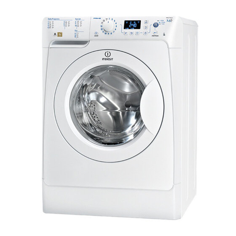
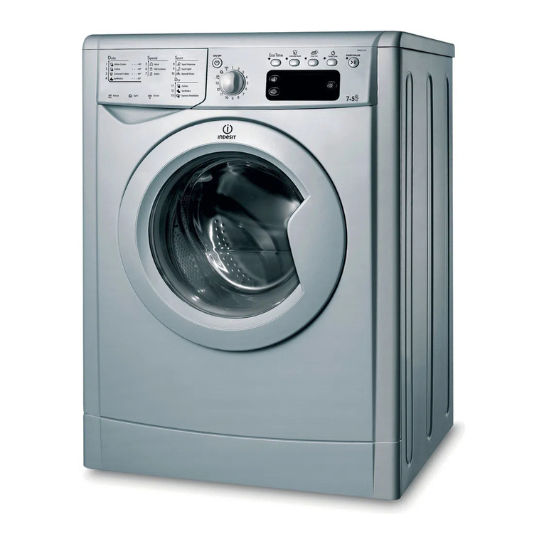
  9. Indesit IWDE 12 User manual

Indesit IWDE 12 User manual

Other manuals for IWDE 12

1

Other Indesit Washer Dryer manuals

Indesit XWDE 751680 User manual

Indesit

Indesit XWDE 751680 User manual

Indesit XWDE 751480 User manual

Indesit

Indesit XWDE 751480 User manual

Indesit IWDE 7125 User manual

Indesit

Indesit IWDE 7125 User manual

Indesit WD 125 T User manual

Indesit

Indesit WD 125 T User manual

Indesit PWDE 7125 S User manual

Indesit

Indesit PWDE 7125 S User manual

Indesit DRYER WIDL 126 S User manual

Indesit

Indesit DRYER WIDL 126 S User manual

Indesit IWDC 6145 User manual

Indesit

Indesit IWDC 6145 User manual

Indesit IWDC 6125 User manual

Indesit

Indesit IWDC 6125 User manual

Indesit PWDE 7124 W User manual

Indesit

Indesit PWDE 7124 W User manual

Indesit IWDC 7085 User manual

Indesit

Indesit IWDC 7085 User manual

Indesit WIB101 User manual

Indesit

Indesit WIB101 User manual

Indesit WD 12 S User manual

Indesit

Indesit WD 12 S User manual

Indesit XWDE 961680 User manual

Indesit

Indesit XWDE 961680 User manual

Indesit WIDL 102 User manual

Indesit

Indesit WIDL 102 User manual

Indesit WIL143UK User manual

Indesit

Indesit WIL143UK User manual

Indesit WIDE 146 User manual

Indesit

Indesit WIDE 146 User manual

Indesit IWDE 7105 User manual

Indesit

Indesit IWDE 7105 User manual

Indesit WDE 12 X User manual

Indesit

Indesit WDE 12 X User manual

Indesit WIDL 106 User manual

Indesit

Indesit WIDL 106 User manual

Indesit WDG 862 User manual

Indesit

Indesit WDG 862 User manual

Indesit IWDE 7168 User manual

Indesit

Indesit IWDE 7168 User manual

Indesit WIDE127 User manual

Indesit

Indesit WIDE127 User manual

Indesit IWDE 7145 K User manual

Indesit

Indesit IWDE 7145 K User manual

Indesit WD 14 User manual

Indesit

Indesit WD 14 User manual

Popular Washer Dryer manuals by other brands

Whirlpool WFC8090GX Use and care guide and installation instructions

Whirlpool

Whirlpool WFC8090GX Use and care guide and installation instructions

GE GUD27GSSM2WW installation instructions

GE

GE GUD27GSSM2WW installation instructions

Beko WDIX7523000 user manual

Beko

Beko WDIX7523000 user manual

Beko HTV 8733 XS0 user manual

Beko

Beko HTV 8733 XS0 user manual

Ariston Margherita AL 108 D Instructions for installation and use

Ariston

Ariston Margherita AL 108 D Instructions for installation and use

GE GTUN275GMWW owner's manual

GE

GE GTUN275GMWW owner's manual

Frigidaire FLSG62MRFS4 installation instructions

Frigidaire

Frigidaire FLSG62MRFS4 installation instructions

AEG L7WEE861 user manual

AEG

AEG L7WEE861 user manual

Hoover Performa Family Instruction book

Hoover

Hoover Performa Family Instruction book

Ariston Margherita AWD 12 Instructions for installation and use

Ariston

Ariston Margherita AWD 12 Instructions for installation and use

Speed Queen Horizon Specification sheet

Speed Queen

Speed Queen Horizon Specification sheet

Smeg WDI14C7-2 instruction manual

Smeg

Smeg WDI14C7-2 instruction manual

LG WDV5149 VP Series owner's manual

LG

LG WDV5149 VP Series owner's manual

Smeg WDF6127-1 instruction manual

Smeg

Smeg WDF6127-1 instruction manual

GE Unitized Spacemaker WSM2480DWW Dimension Guide

GE

GE Unitized Spacemaker WSM2480DWW Dimension Guide

Frigidaire Laundry Center Installation

Frigidaire

Frigidaire Laundry Center Installation

EdgeStar CWD1510S owner's manual

EdgeStar

EdgeStar CWD1510S owner's manual

Splendide WD2000S Training guide

Splendide

Splendide WD2000S Training guide

manuals.online logo
manuals.online logoBrands
  • About & Mission
  • Contact us
  • Privacy Policy
  • Terms and Conditions

Copyright 2025 Manuals.Online. All Rights Reserved.

1
GB
English,1
Contents
Installation, 2-3-4-5-6-7
Unpacking and levelling
Electric and water connections
The first wash cycle
Technical details
Instructions for the fitter
Washer-dryer description, -9
Control panel
Leds
Starting and Programmes, 10
Briefly: how to start a programme
Programme ta le
Personalisations, 11
Setting the temperature
Setting the drying cycle
Functions
Detergents and laundry, 12
Detergent dispenser
Preparing your laundry
Special items
Precautions and advice, 13
General safety
Disposal
Saving energy and respecting the environment
Care and maintenance, 14
Cutting off the water or electricity supply
Cleaning your appliance
Cleaning the detergent dispenser
Caring for your appliance door and drum
Cleaning the pump
Checking the water inlet hose
Troubleshooting, 15
Service, 16-17-1
Before calling for Assistance
WASHER-DRYER
IWDE 12
Instructions for use
GB
2
GB
Installation
Keep this instruction manual in a safe place for
future reference. Should the appliance e sold,
transferred or moved, make sure the instruction
manual accompanies the washer-dryer to inform the
new owner as to its operation and features.
Read these instructions carefully: they contain vital
information on installation, use and safety.
Unpacking and levelling
Unpacking
1. Unpack the washer-dryer.
2. Check whether the washer-dryer has een
damaged during transport. If this is the case, do not
install it and contact your retailer.
3. Remove the 4
protective screws and
the ru er ush with the
respective spacer,
situated on the rear of
the appliance (see also
the installation leaflet).
NB:The plastic spacers
may fall down inside the
machine once the olt
has een removed, and will not interfere with the
operation of the machine.
4. Seal the gaps using the plastic plugs provided.
5. Keep all the parts: you will need them again if the
washer-dryer needs to e moved to another
location.
Packaging materials are not children's toys.
Levelling
Your machine may make a considera le amount of noise
if the two front feet have not een adjusted correctly.
1. Install the washer-dryer on a flat sturdy floor,
without resting it up against walls, furniture ca inets
or other.
2. If the floor is not
perfectly level, compen-
sate for any unevenness
y tightening or
loosening the adjusta le
front feet (see figure);
the angle of inclination,
measured according to
the worktop, must not
exceed 2°.
Levelling your appliance correctly will provide it with
sta ility and avoid any vi rations, noise and shifting
during operation. If it is placed on a fitted or loose
carpet, adjust the feet in such a way as to allow
enough room for ventilation eneath the washer-
dryer.
Electric and water connections
Connecting the water inlet hose
1. Insert seal A into the
end of the inlet hose
and screw the latter
onto a cold water tap
with a 3/4 gas threaded
mouth (see figure).
Before making the
connection, allow the
water to run freely until
it is perfectly clear.
2. Connect the other end
of the water inlet hose to
the washer-dryer,
screwing it onto the
appliance's cold water
inlet, situated on the top
right-hand side on the
rear of the appliance (see
figure).
3. Make sure there are no kinks or ends in the
hose.
The water pressure at the tap must e within the
values indicated in the Technical details ta le
(on the next page).
If the water inlet hose is not long enough, contact
a specialist store or an authorised serviceman.
Ensure that the supply taps are allowing water
through. Old taps may seize in the closed position
and thus prevent water reaching the machine.
A
3
GB
 the supply voltage is included within the values i
ndicated on the Technical details ta le
(see page 5);
 the socket is compati le with the washing
machine's plug. If this is not the case, replace
the socket or the plug.
Your appliance is now supplied with a 13 amp fused
plug it can e plugged into a 13 amp socket for
immediate use. Before using the appliance please
read the instructions elow.
WARNING - THIS APPLIANCE MUST BE EARTHED.
THE FOLLOWING OPERATIONS SHOULD BE
CARRIED OUT BY A QUALIFIED ELECTRICIAN.
Replacing the fuse:
When replacing a faulty fuse, a 13 amp ASTA
approved fuse to BS 1362 should always e used,
and the fuse cover re-fitted. If the fuse cover is lost,
the plug must not e used until a replacement is
o tained.
Replacement fuse covers:
If a replacement fuse cover is fitted, it must e of
the correct colour as indicated y the coloured
marking or the colour that is em ossed in words on
the ase of the plug. Replacements can e o tained
directly from your nearest Service Depot.
Removing the plug:
If your appliance has a non-rewirea le moulded plug
and you should wish to re-route the mains ca le
through partitions, units etc., please ensure that
either:
the plug is replaced y a fused 13 ampere re-
weara le plug earing the BSI mark of approval.
or:
the mains ca le is wired directly into a 13 amp ca le
outlet, controlled y a switch, (in compliance with
BS 5733) which is accessi le without moving the
appliance.
Disposing of the plug:
Ensure that efore disposing of the plug itself, you
make the pins unusa le so that it cannot e
accidentally inserted into a socket.
Instructions for connecting ca le to an alternative plug:
Important: the wires in the mains lead are coloured
in accordance with the following code:
Green & Yellow Earth
Blue Neutral
Brown Live
Connecting the drain hose
Connect the drain hose,
without ending it, to a
draining duct or a wall
drain situated etween
65 and 100 cm from
the floor;
The drain hose may e
connected to an
under-sink trap. Before
connecting the drain
hose from the machine
ensure that any lanks
or remova le ends
have een taken off
the spigot.
If it is place over the
edge of a asin or sink
e sure the free end of
the hose should not e
underwater.
 We advise against the use of hose extensions; in
case of a solute need, the extension must have the
same diameter as the original hose and must not
exceed 150 cm in length.
Ensure that if the drain hose is pushed into a
standpipe, that the end does not go down more
than 15cms (6 inches). If the hose is pushed down
too far, this may cause the machine to self -syphon
ie. continuously empty as it is filling.
Electric connection
Before plugging the appliance into the mains
socket, make sure that:
 the socket is earthed and in compliance with the
applica le law;
 the socket is a le to sustain the appliance's
maximum power load indicated in the Technical
details ta le (see page 5);
65 - 100 cm
4
GB
As the colours of the wires in the lead may not
correspond with the coloured markings identifyng
the terminals in your plug, proceed as follows:
Connect Green & Yellow wire to terminal marked E
or or coloured Green or Green & Yellow.
Connect Brown wire to terminal marked L or
coloured Red.
Connect Blue wire to terminal marked N or coloured
Black.
If a 13 amp plug (BS 1363) is used it must e fitted
with a
13 amp fuse, either in the plug or adaptor or at the
distri ution oard.
If you are in any dou t the electrical supply to your
machine, consult a qualified electrician efore use.
How to connect an alternative plug:
The wires in this mains lead are coloured in
accordance with the following code:
BLUE NEUTRAL (N)
BROWN LIVE (L)
GREEN & YELLOW EARTH (E)
Disposing of the appliance:
When disposing of the appliance please remove the
plug y cutting the mains ca le as close as possi le
to the plug ody and dispose of it as descri ed
a ove.
 The washer-dryer should not e installed in an
outdoor environment, not even when the area is
sheltered, ecause it may e very dangerous to
leave it exposed to rain and thunderstorms.
 When the washer-dryer is installed, the mains
socket must e within easy reach.
 Do not use extensions or multiple sockets.
 The power supply ca le must never e ent or
dangerously compressed.
 The power supply ca le must only e replaced y
an authorised serviceman.
Warning! The company denies all lia ility if and when
these norms are not respected.
The first wash cycle
Once the appliance has een installed, and efore
you use it for the first time, run a wash cycle with
detergent and no laundry, setting the 90°C
programme without a pre-wash cycle.
GREEN &
YELLOW
BROWN
BLUE
13 ampere fuse
CROSS-BAR
CORD GRIP
5
Technical details
Model IWDE 12
Dimensions
59.5 cm wide
81.5 cm high
54 cm deep
Capacity from 1 to 5,5 kg for the wash programme;
from 1 to 4 kg for the drying programme
Electric
connections
please refer to the technical data plate
fixed to the machine
Wat e r
connections
maximum pressure 1 MPa (10 ar)
minimum pressure 0.05 MPa (0.5 ar)
drum capacity 52 litres
Spin speed up to 1200 rpm
Control
programmes
according to
EN 50229
directive
Wash: programme 2; temperature 60°C;
run with a load of 5,5 kg.
Drying: first drying cycle performed with
a 1 kg load, y selecting a drying time
of 40 min;
Second drying cycle performed with a
4 kg load and the DRYING kno on
the setting.
This appliance is compliant with the
following European Community
Directives:
- 73/23/CEE of 19/02/73 (Low
Voltage) and su sequent amendments
- 89/336/CEE of 03/05/89
(Electromagnetic Compati ility) and
su sequent amendments
- 2002/96/CE
6
GB
Instructions for the fitter
Mounting the wooden panel onto the door and
inserting the machine into cabinets:
In the case where the machine must e shipped for final
installation after the wooden panel has een mounted, we
suggest leaving it in its original packaging. The packaging
was designed to make it possi le to mount the wooden
panel onto the machine without removing it completely
(see figures below).
The wooden panel that covers the face of the machine
must not e less than 18 mm in thickness and can e
hinged on either the right or left. For the sake of
practicality when using the machine, we recommend that
the panel e hinged on the same side as the door for the
machine itself - the left.
AB
CD
E
Door Mounting Accessories (Fig. 1-2-3-4-5).
Fig. 1
N° 2 Hinges
N° 1 Magnet N° 1 Magnet plate
N° 1 Rubber plug
N° 2 Hinge Supports
N° 1 Spacer
Fig. 2
Fig. 3 Fig. 4
Fig. 5 Fig. 4/B
- No. 6 type A self-threading screws, l =13 mm.
- No. 2 type B metric, countersunk screws, l =25; for
fastening the magnet plate to the ca inet.
- No. 4 type C metric screws, l =15 mm; for mounting the
hinge supports to the ca inet.
- No. 4 type D metric screws, l =7 mm; for mounting the
hinges on the supports.
Mounting the Parts onto the Face of the Machine.
- Mount the hinge supports onto the face of the machine,
positioning the hole indicated y the arrow in fig. 1 towards
the inside of the face and using the type C screws.
- Mount the magnetic plate on the opposite side, at the
top, using the two type B screws.
- Place the spacer illustrated in fig. 4/ etween the
appliance front and the magnet receiver.
Tur seite
7
GB
Using the Drilling Template.
- To trace the positions of the holes on the left-hand side
of the panel, align the drilling template to the top left side
of the panel using the lines traced on the extremities as a
reference.
- To trace the positions of the holes on the right-hand
side of the panel, align the drilling template to the top
right side of the panel.
- Use an appropriately sized router to mill the holes for
the two hinges, the ru er plug and the magnet.
Mounding the Parts onto the Wooden Panel (Door).
- Insert the hinges into the holes (the mova le part of the
hinge must e positioned facing away from the panel) and
fasten them with the 4 type A screws.
- Insert the magnet into the top hole on the opposite side
of the hinges and fasten it with the two type B screws.
- Insert the ru er plug into the ottom hole.
The panel is now ready to e mounted onto the machine.
Mounting the Panel into the machine.
Insert the ni of the hinge (indicated y the arrow in fig. 2)
into the hole for the hinge and push the panel towards the
front of the machine. Fasten the two hinges with the type
D screws.
Fastening the plinth guide.
If the machine is installed at the end of a set of modular
ca inets, mount either one or oth of the guides for the
ase molding (as shown in fig. 8). Adjust them for depth
ased on the position of the ase molding, and, if
necessary, fasten the ase to the guides (fig. 9).
This is how to assem le the plinth guide (fig. 8):
Fasten angle P using screw R, insert plinth guide Q into
the special slot and once it is in the desired position, lock
it in place using angle P and screw R.
Inserting the machine into the Cabinet.
- Push the machine into the opening, aligning it with the
ca inets (fig. 6).
- Regulate the adjusta le feet to raise the machine to the
appropriate height.
- To adjust the position of the wooden panel in oth the
vertical and horizontal directions, use the C and D
screws, as shown in fig. 7.
Important: close the lower part of the appliance front by
ensuring that the plinth rests against the floor.
Fig. 8 Fig. 9
Accessories provided for the height adjustment.
The following can e found inside the polystyrene lid (fig. 10):
2 cross ars (G), 1 strip (M)
the following can e found inside
the appliance drum:
4 additional feet (H),
4 screws (I),
4 screws (R),
4 nuts (L),
2 plinth guides (Q)
Adjusting the appliance height.
The height of the appliance can e adjusted (from 815 mm
to 835 mm), y turning the 4 feet.
Should you require the appliance to e placed higher than
the a ove height, you need to use the following accessories
to raise it to up to 870 mm:
the two cross ars (G); the 4 feet (H); the 4 screws (I); the 4
nuts (L) then perform the following operations (fig. 11):
remove the 4 original feet, place a cross ar G at the front of
the appliance, fastening it in place using screws I (screwing
them in where the original feet were) then insert the new feet H.
Repeat the same operation at the ack of the appliance.
Now adjust feet H to raise or lower the appliance from 835
mm to 870 mm.
Once you have reached the desired height, lock nuts L onto
cross ar G.
To adjust the appliance to a height etween 870 mm and
900 mm, you need to mount strip M, adjusting feet H to the
required height.
Insert the strip as follows:
loosen the three screws N situated at the front of the Top
cover of the appliance, insert strip M as shown in fig. 12,
then fasten screws N.
D
C
C
Fig. 6 Fig. 7
LI
H
G
M
Fig. 11 Fig. 12
Fig. 10
570
min
815
540
595
820 ÷ 900
600 min
GB
Washer-dryer description
Control panel
Detergent dispenser: to add detergent and fa ric
softener (see page 12).
LEDS: to find out which wash cycle phase is under
way.
If the Delay Timer function has een set, the time
left until the programme starts will e indicated (see
page 9).
DRYING kno : to set the desired drying cycle
(see page 11).
FUNCTION uttons: to select the functions
availa le. The utton corresponding to the function
selected will remain on.
TEMPERATURE kno : to set the temperature or
the cold wash cycle (see page 11).
START/RESET utton: to start the programmes or
cancel any incorrect settings.
ON-OFF/DOOR LOCK Led: to find out whether the
Washer-dryer is on and if the appliance door can e
opened (see page 9).
ON/OFF utton: to turn the Washer-dryer on and off.
PROGRAMME kno : to select the wash
programmes. The kno stays still during the cycle.
Note: to avoid excessive vibrations, before every spin cycle the machine distributes the load in a uniform manner
by continuously rotating the drum at a speed which is slightly faster than the normal washing speed.
When, despite repeated attempts, the load is still not evenly distributed, the machine spins at a lower speed than
the set frequency.
If the load is excessively unbalanced, the machine attempts to distribute it instead of spinning.
The balancing attempts may extend the total duration of the cycle, up to a maximum of 10 minutes.
Detergent dispenser
ON-OFF
Button
START/RESET
Button
TEMPERATURE
Kno
Leds
FUNCTION
Buttons
DRYING
Kno
ON-OFF/DOOR
LOCK
Led
9
GB
ON-OFF/DOOR LOCK led:
If this LED is on, the appliance door is locked to prevent it from eing opened accidentally; to avoid any
damages, wait for the LED to flash efore you open the appliance door.
 The rapid flashing of the ON-OFF/DOOR LOCK Led together with the flashing of at least one other LED
indicates there is an a normality (see page 15).
Cycle phase under way:
During the wash cycle, the LEDs gradually illumina-
te on to indicate the cycle phase under way:
Prewash / Wash
Rinse
Spin cycle
Drying
Note:
- during draining, the LED corresponding to the
Spin cycle phase will e turned on.
- when the drying cycle is complete, the indicator
light relative to phase will flash, to indicate that
the DRYING kno needs to e set ack to the 0
setting.
Function buttons
The FUNCTION BUTTONS also act like LEDS.
When a function is selected, the corresponding
utton is illuminated.
If the function selected is incompati le with the
programme set, the utton will flash and the
function will not e ena led.
If you set a function that is incompati le with
another function you selected previously, only the
last one selected will e ena led.
Leds
The LEDS provide important information.
This is what they can tell you:
Delay set:
If the Delay Timer function has een ena led (see
page. 11), once you have started the programme,
the LED corresponding to the delay set will egin to
flash:
As time passes, the remaining delay will e
displayed, and the corresponding LED will flash:
Once the set delay is complete, the flashing LED will
turn off and the programme set will start.
10
GB
Type of fabric and
degree of soil Program. Te m p e -
rature
rying
Cycle
etergent Fabric
softener
Cycle
length
(minutes)
escription of wash cycle
pre-
wash wash
Standard
Cotton: Extremely soiled whites
(sheets, ta lecloths, etc.) 190°C     155 Pre-wash, wash cycle, rinse cycles,
intermediate and final spin cycles
Cotton: Extremely soiled whites
(sheets, ta lecloths, etc.) 290°C  -150 Wash cycle, rinse cycles,
intermediate and final spin cycles
Cotton: Heavily soiled whites and
fast colours 260°C  -140 Wash cycle, rinse cycles,
intermediate and final spin cycles
Cotton: Heavily soiled whites and
delicate colours 240°C  -125 Wash cycle, rinse cycles,
intermediate and final spin cycles
Cotton: Slightly soiled whites and
delicate colours (shirts, jumpers, etc.) 340°C  - 85 Wash cycle, rinse cycles,
intermediate and final spin cycles
Synthetics: Heavily soiled fast
colours ( a y linen, etc.) 450°C - 83 Wash cycle, rinse cycles, anti-crease
or delicate spin cycle
Synthetics: Heavily soiled fast
colours ( a y linen, etc.) 440°C  - 70 Wash cycle, rinse cycles, anti-crease
or delicate spin cycle
Wool 540°C --
 50 Wash cycle, rinse cyclese, delicate
spin cycle
Very delicate fa rics
(curtains, silk, viscose, etc.) 630°C --
 45 Wash cycle, rinse cycles, anti-crease
or draining cycle
Drying cotton 7--- - -
Drying delicates 8--- - -
Tim e 4 you
Cotton: Heavily soiled whites and
fast colours 960°C --
 60 Wash cycle, rinse cycles,
intermediate and final spin cycles
Synthetics: Delicate colours
(all types of slightly soiled garments) 10 40°C --
 40 Wash cycle, rinse cycles, delicate
spin cycle
Synthetics: Delicate colours
(all types of slightly soiled garments) 11 30°C  - 30
Wash cycle, rinse cycles and delicate
spin cycle
Sport
Sports shoes (MAX. 2 pairs) 12 30°C --
 50
Cold wash (without detergents), wash
cycle, rinse cycles, and delicate spin cycle
Fa rics for sportswear
(Tracksuits, shorts, etc.) 13 30°C --
 60
Wash cycle, rinse cycles,
intermediate and final spin cycles
PARTIAL PROGRAMMES
Rinse --- -Rinse cycles and spin cycle
Spin cycle --- - -
Draining and spin cycle
Drain ----- -
Drain
Starting and Programmes
Programme table
Briefly: starting a programme
1. Switch the Washer-dryer on y pressing utton .
All the LEDS will light up for a few seconds and
the ON-OFF/DOOR LOCK Led will egin to flash.
2. Load your laundry into the washer-dryer and
shut the appliance door.
3. Set the PROGRAMME kno to the programme
required.
4. Set the wash temperature (see page 11).
5. Set the drying cycle if necessary (see page 11).
6. Add the detergent and any fa ric softener (see page 12).
7. Start he programme y pressing the START/RESET
utton.
To cancel it, keep the START/RESET utton pressed
for at least 2 seconds.
8. When the programme is finished, the ON-OFF/
DOOR LOCK Led will flash to indicate that the
appliance door can e opened. Take out your
laundry and leave the appliance door ajar to allow
the drum to dry thoroughly. Turn the Washer-dryer
off y pressing utton .
Notes
-For programme 9, we advise against exceeding a wash load of 3.5 kg.
-For programme 13 we advise against exceeding a wash load of 2 kg.
-For the anti-crease function: see Easy iron, opposite page. The information contained in the ta le is purely indicative.
Special programme
Daily (programme 11 for Synthetics) is designed to wash lightly soiled garments in a short amount of time: it only lasts
30 minutes and allows you to save on oth time and energy. By setting this programme (11 at 30°C), you can wash
different fa rics together (except for woollen and silk items), with a maximum load of 3 kg.
We recommend the use of liquid detergent.