manuals.online logo
Brands
  1. Home
  2. •
  3. Brands
  4. •
  5. Indigo
  6. •
  7. Lighting Equipment
  8. •
  9. Indigo SPRINGBOK LITE 3 User manual

Indigo SPRINGBOK LITE 3 User manual

INSTRUCTIONS / INSTRUCTIES / GEBRAUCHSANLEITUNG
ACKLEUR COLORCODE LED T° (K) LED LumenFARBECOULEUR
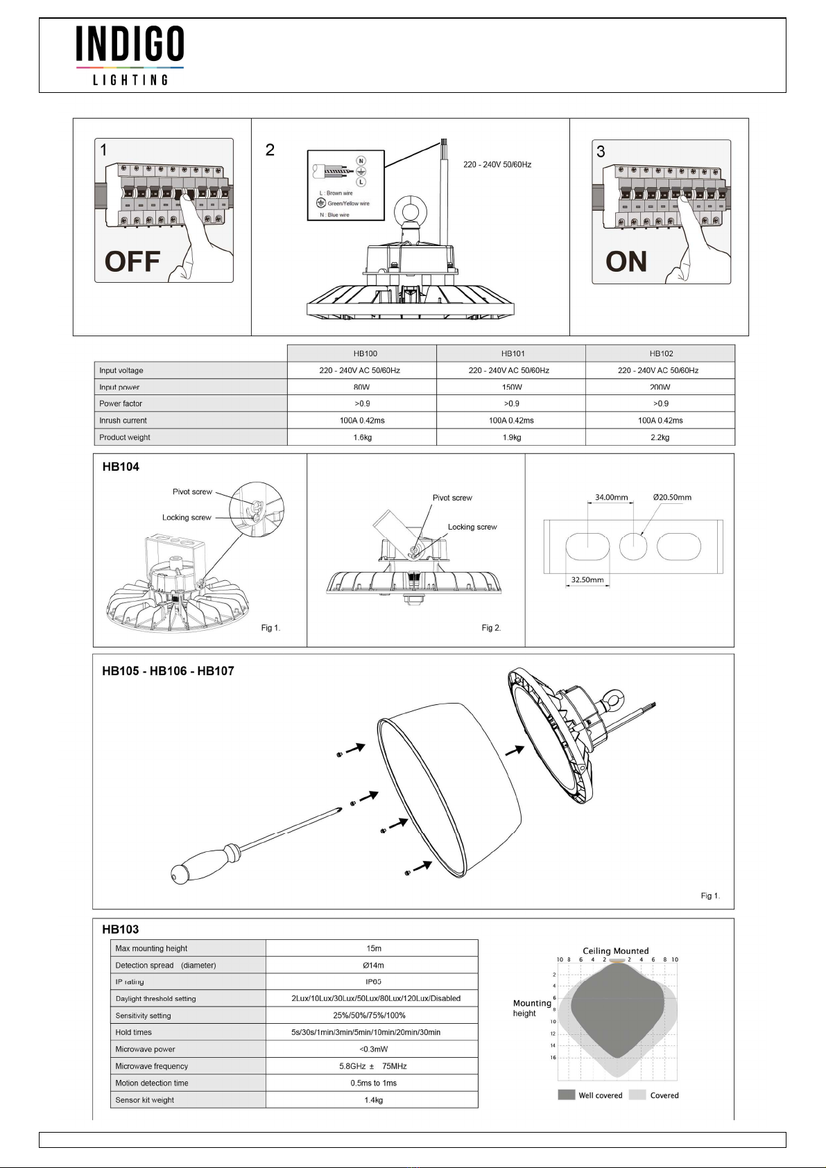
HB102WW05
NOIR ZWART 200W 3000K 29200 LmAC 230VBLACKSCHWARZ
HB102NW05
NOIR ZWART 200W 4000K 31050 LmAC 230VBLACKSCHWARZ
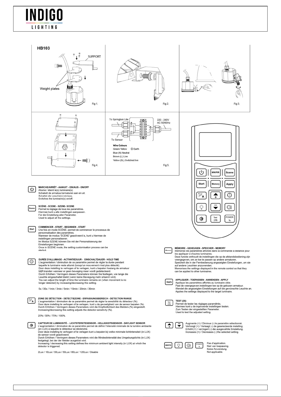
SPRINGBOK LITE 3
energiezuinig D.
d’efficacité énergétique D.F Ce produit contient 1 source(s) lumineuse(s)
E This product contains 1 light source(s) of energy efficiency D.N Dit product bevat 1 lichtbron(nen)
D Dieses Produkt enthält 1 Lichtquelle(n) mit D energieeffizient.
N EDF
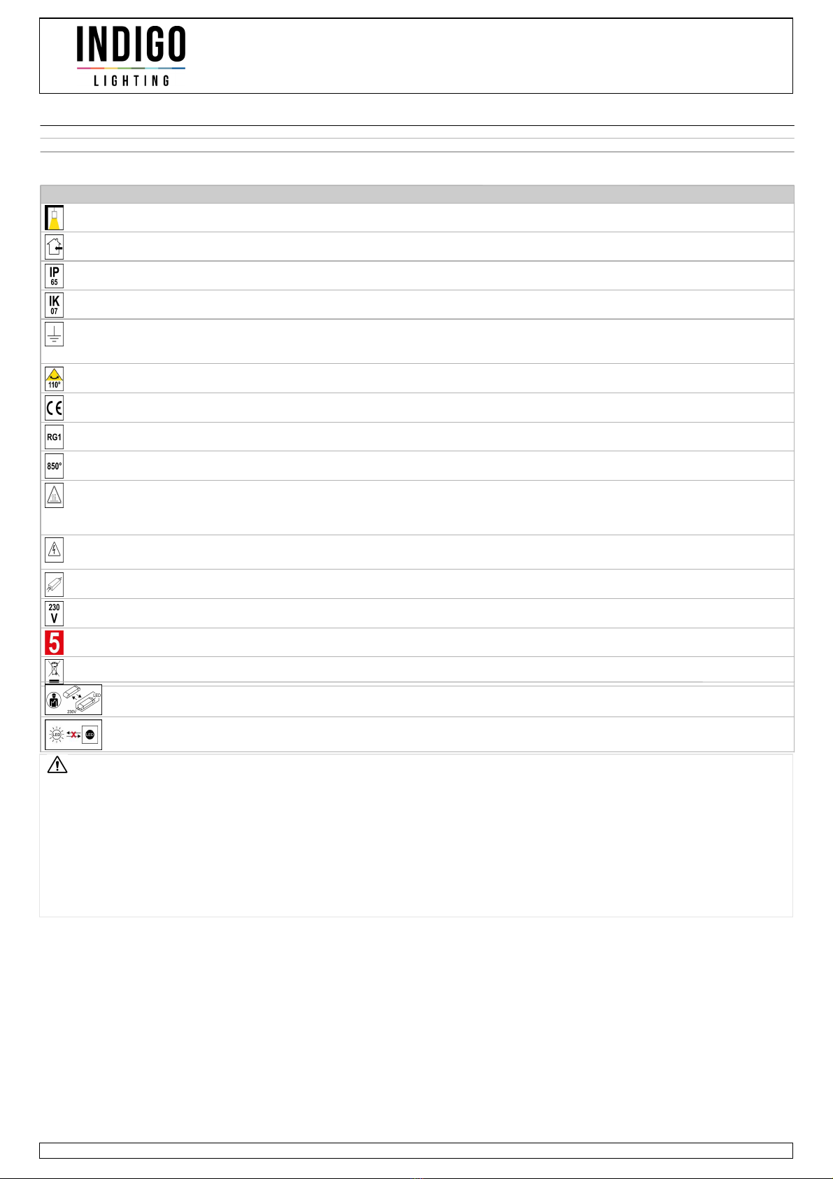
Montage en suspension. Pendelmontage. Suspended mounting only.Nur für Aufhängmontage.
Usage intérieur uniquement. Alleen voor binnengebruik. Indoor use only.Nur für den Innengebrauch.
Etanchéité aux poussières. Protection contre
les jets d’eau.
Stofdicht. Bescherming tegen waterstralen. Protected against the ingress of dust. Protected
against jets of water.
Staubdicht. Schutz gegen Wasserstrahlen.
Protection contre une énergie de choc de 2
Joules.
Bescherming tegen een impact-energie van 2
Joule.
Protection against an impact energy of 2
Joules.
Schutz gegen eine Stoßenergie von 2 Joule.
Produit à isolation principale qui comporte
des dispositifs reliant l’ensemble de ses
parties métalliques accessibles au
conducteur de protection.
Product met hoofdisolatie, met een apparaat
dat alle metalen delen die toegankelijk zijn
met de beschermingsleiding verbindt.
Earth wire . Fixture equipped with primary
insulation only.
Beleuchtung mit Hauptisolierung, mit einem
Gerät welches alle seine Metallteile die
zugänglich sind mit dem Schutzleiter
verbindet.
Faisceau 110°. Lichtbundel 110°. Beam 110°.Strahlwinkel 110°.
Homologation CE. CE gekeurd. Product in conformity CE.CE Genehmigung.
Risque photobiologique RG1 Fotobiologisch risico RG1 Photobiological risk RG1Photobiologisches Risiko RG1
Testé à 850°. Getest bij 850°. Test on 850°.Getestet bei 850°.
Produit sous haute température en
fonctionnement. Interdiction d'avoir des objets
ou des parois proches pendant toute la durée
de dégagement de chaleur. Même après
extinction.
Product onder hoge temperatuur bij werking.
Verbod voorwerpen of muren nabij te hebben
gedurende de hele oververhitting, zelfs na
uitdoving.
Produkt emitting high temperature. Can not be
installed too close of walls and objects even
after extinction.
Produkt unter hoher Temperatur bei Betrieb.
Verbot Gegenstände oder Wände in der
Nähe zu haben während der ganzen Dauer
der Überhitzung, auch nach dem Erlöschen.
Attention ! Risque d'électrocution. Extinction
de la source électrique avant chaque
manipulation.
Let op gevaar voor elektrokuteren. Afsluiten
van de stroom voor iedere manipulatie.
Attention! Risk of electric shock. Switch off
before any intervention on the luminaire.
Achtung Gefahr eines elektrischen Schlags.
Stromquelle abschliessen bevor jede
Manipulation.
Alimentation incluse. Voeding inbegrepen. Power supply included.Stromversorgung einbegriffen.
A connecter à un courant alternatif de 230V. Aan te sluiten op een AC-circuit van 230V. To connect to a 230V AC circuit.An eine AC-Schaltung von 230 Volt an zu
schliessen.
Garantie 5 ans. 5 jaar garantie. 5 years warranty.5 Jahre Garantie.
L'appareil doit être éliminé dans des centres
de ramassage spécialisés.
Het toestel moet worden afgevoerd in een
speciale collectie centra.
Luminaire must be disposed in specialized
collection center.
Das Gerät muss von einer speziellen
Sammelstelle entsorgt werden.
Driver remplaçable par un
électricien.
Driver vervangbaar door elektricien. Replaceable control gear by an electrician.Driver von einem Elektriker austauschbar.
LED non remplaçable. Niet-vervangbare lichtbron. Non-replaceable light source.Lichtquelle nicht austauschbar.
• Ce document doit être conservé pendant
toute la durée de vie du produit.
• Le produit ne sera ni échangé, ni repris en
cas d'erreur de montage.
• INDIGO se réserve le droit de modifier les
spécifications sans préavis.
• Dit document moet worden bewaard voor
de hele levensduur van het product.
• Dieses Dokument muss für die ganze
Lebensdauer des Produkts aufbewahrt
werden.
• This document must be kept for the all
lifetime of the product.
• Het product wordt nog terug genomen, nog
vervangen bij foutieve installatie.
• Das Produkt wird weder zurückgenommen
noch umgetauscht bei falscher Installation.
• The product can't be returned or
exchanged following to installation error.
• INDIGO behoudt zich het recht om
specificaties te wijzigen zonder
voorafgaande kennisgeving.
• INDIGO behält das Recht für
Spezifikationen, ohne vorherige
Ankündigung, zu ändern.
• INDIGO reserve the right to modify
specifications without prior notice.
• Toutes les sources de chaleur (ampoules,
transformateurs, convertisseurs, …) doivent
obligatoirement être suffisamment espacées
et ventilées pour empêcher l'incendie.
Veuillez nous contacter lors de cas
particulier de montage.
• Alle warmtebronnen (lampen,
transformatoren, omvormers, ...) moeten
voldoende worden geventileerd en op een
voldoende afstand zijn om de brand te
voorkomen. Neem contact met ons op in
geval van speciale montage.
• Alle Wärmequellen (Lampen,
Transformatoren, Umformer, ...) müssen
ausreichend belüftet sein und einen
genügenden Abstand haben um das Feuer
zu verhindern. Bitte kontaktieren Sie uns bei
einer speziellen Montage.
• All heat source (bulbs, transformers,
converters, …) are required to be
sufficiently spaced and ventilated to prevent
the fire.
Please contact us in case of special
installation.
The fixture should be assembled and
installed by professionals and used only
to illuminate.
De armatuur moet worden gemonteerd en
geïnstalleerd door vakmensen en dient
alleen om te verlichten.
Le luminaire doit être monté et installé
par un professionnel et il sert
uniquement à éclairer.
Die Leuchte darf nur von Fachleuten
montiert und installiert werden und dient
nur zur Beleuchtung.
INDIGO S.A. / N.V. Rue de la légende 32 G, 4141 Sprimont - Belgique www.indigo-lighting.com 06.11.2023
INSTRUCTIONS / INSTRUCTIES / GEBRAUCHSANLEITUNG
HB100 - HB101 - HB102 :
A. Soulevez la suspension industrielle à l’aide d’une chaîne appropriée (non-fournie) et attachez-la à la boucle de suspension M10 fournie. Le poids du produit doit être pris
en compte lors du choix de la chaîne.
B. Serrez la vis de fixation sur le côté de la boucle.
C. Le produit peut également être monté à l’aide de l'étrier de fixation réglable vendu séparément.
D. Connectez la suspension industrielle à l’alimentation secteur.
Remarque: N’installez pas ce luminaire avec des lampes HID sur le même circuit.
HB104 :
L'étrier de fixation réglable est conçu pour être monté sur une goulotte d'éclairage via un filetage central M20, mais il peut aussi être vissé sur d’autres surfaces.
A. Positionnez l'étrier sur le produit. Insérez les rondelles, les vis d’articulation et de verrouillage fournies et serrez partiellement pour que l'étrier puisse s’incliner (fig. 1).
B. Réglez l’angle d’inclinaison du produit selon la position voulue, puis serrez complètement les vis d’articulation et de verrouillage pour fixer le produit (fig. 2).
C. Montez l'étrier sur le filetage M20 ou sur la surface de montage et fixez.
HB103 :
A. Fixez les deux plaques de poids et le support de montage au détecteur à l’aide des trois vis fournies (fig. 1).
B. Fixez le support du détecteur sur le côté du luminaire en utilisant l’une des deux positions de montage et les boulons M8 fournis. Serrez bien les boulons (fig. 2).
C. Si vous utilisez le réflecteur 80° (accessoire vendu séparément réf. HB105 - HB106 - HB107), fixez les 2 plaques de poids au détecteur à l’aide des 3 vis fournies. Ensuite,
fixez le détecteur directement sur le réflecteur à l’aide du clip de montage pré-attaché (fig. 3).
L’utilisation du support du détecteur lors du montage sur le réflecteur n’est pas nécessaire, cet élément peut être éliminé.
D. Fixez le support de la boîte de jonction sur le côté du luminaire opposé au détecteur à l’aide du boulon M8 fourni, de la même manière que pour le support du détecteur.
E. Fixez la boîte de jonction sur le support à l’aide des 2 vis fournies, en notant l’emplacement des 2 trous de vis sur le support (fig. 4).
Une fois installée, la boîte de jonction sert de contrepoids au détecteur.
F. Connectez les fils d’alimentation du détecteur et du luminaire dans la boîte de jonction (fig. 5).
G. Replacez le couvercle supérieur et fixez à l’aide des 4 vis fournies.
HB115 :
La commande à distance est conçue pour être utilisée avec le SPRINGBOK LITE équipé du kit de détecteur HB103 (vendu séparément).
La portée maximale de la commande à distance est de 12m.
Configuration des paramètres et application des réglages au luminaire :
A. Enlevez le couvercle du compartiment piles et assurez-vous que 2 piles AAA sont installées et que la languette est retirée.
B. Appuyez sur le bouton SCENE pour afficher tous les paramètres disponibles à l’écran.
C. Appuyez sur le bouton START pour accéder au mode configuration (un “S” clignotant apparaitra dans la partie inférieure gauche de l’écran).
D. Appuyez sur le bouton du paramètre à régler pour le mettre en surbrillance.
E. Réglez le paramètre en surbrillance sur la valeur souhaitée à l’aide des boutons de réglage + et -.
F. Passez au paramètre suivant à régler en appuyant sur le bouton correspondant et utilisez les boutons de réglage.
G. Pour enregistrer les valeurs des paramètres affichés, appuyez sur le bouton MEMORY (un “M” statique apparaitra dans la zone inférieure gauche de l’écran). Les
paramètres sont enregistrés dans la commande à distance.
H. Pour appliquer les valeurs des paramètres affichés au luminaire, pointez la commande à distance vers le luminaire souhaité (équipé d'un détecteur HB103) et appuyez sur
APPLY. Le luminaire clignote brièvement pour confirmer la réception des paramètres.
I. Répétez l’étape H pour appliquer les mêmes paramètres à un autre luminaire équipé d'un détecteur.
Bouton MARCHE/ARRET :
Appuyez sur le bouton MARCHE/ARRET et pointez la commande à distance vers le luminaire cible (équipé d'un détecteur HB103) pour allumer / éteindre le produit et mettre
la commande à distance en mode “Basic”. En mode “Basic”, seul le paramètre marche/arrêt est disponible. Le passage en mode “Basic” oblige la commande à distance à
effacer toutes les valeurs des paramètres du mode “Configuration".
F : ATTENTION !
HB100 - HB101 - HB102 :
A. Hang de industriële pendelarmatuur op met een geschikte ketting (niet meegeleverd) en bevestig haar aan de meegeleverde M10 ophanglus. Houd bij het kiezen van de
ketting rekening met het gewicht van het product.
B. Draai de bevestigingsschroef vast aan de zijkant van de ophanglus.
C. U kunt het product ook monteren met behulp van de verstelbare montagebeugel, die apart wordt verkocht.
D. Sluit de industriële pendelarmatuur aan op de netspanning.
Let op: Installeer deze armatuur niet met HID-lampen op hetzelfde circuit.
HB104 :
De verstelbare montagebeugel is ontworpen voor montage op een verlichtingsgoot via een centrale M20-schroefdraad, maar kan ook op andere oppervlakken worden
geschroefd.
A. Plaats de montagebeugel op het product. Plaats de meegeleverde sluitringen, de draaischroeven en de borgschroeven en draai ze gedeeltelijk vast zodat de
montagebeugel kan kantelen (fig. 1).
B. Stel de hoek van het product in op de gewenste positie en draai daarna de draaischroeven en de borgschroeven volledig vast om het product vast te zetten (fig. 2).
C. Plaats de montagebeugel op de M20-schroefdraad of het montageoppervlak en zet hem vast.
HB103 :
A. Bevestig de twee gewichtsplaten en de montagesteun aan de sensor met de drie meegeleverde schroeven (fig. 1).
B. Bevestig de sensorsteun aan de zijkant van de armatuur met een van de twee montageposities en de meegeleverde M8-bouten. Draai de bouten stevig aan (fig. 2).
C. Gebruikt u de 80°-reflector (accessoire apart verkrijgbaar, ref. HB105 - HB106 - HB107), dan bevestigt u de 2 gewichtsplaten op de sensor met de 3 meegeleverde
schroeven. Daarna bevestigt u de sensor rechtstreeks op de reflector met de voorgemonteerde bevestigingsclip (fig. 3).
Het is niet nodig om de sensorsteun te gebruiken bij de montage op de reflector. Dit onderdeel kan weggelaten worden.
D. Bevestig de steun van de lasdoos op de kant van de armatuur tegenover de sensor met de meegeleverde M8-bout, op dezelfde manier als de sensorsteun.
E. Bevestig de lasdoos op de steun met de 2 meegeleverde schroeven. Let daarbij op de plaats van de 2 schroefgaten op de steun (fig. 4).
Eenmaal geïnstalleerd, dient de lasdoos als tegengewicht voor de sensor.
F. Sluit de voedingsdraden van de sensor en de armatuur aan op de lasdoos (fig. 5).
G. Plaats het bovendeksel terug en zet het vast met de 4 meegeleverde schroeven.
HB115 :
De afstandsbediening is gemaakt voor gebruik met de SPRINGBOK LITE, uitgerust met de HB103-sensorkit (wordt apart verkocht).
De afstandsbediening werkt op een maximale afstand van 12m.
Configuratie van de instellingen en toepassing van de afregelingen op de armatuur:
A. Maak het deksel van het batterijvak los en controleer of er 2 AAA-batterijen in zitten en of het lipje is verwijderd.
B. Druk op de knop 'SCENE' om alle beschikbare instellingen op het scherm weer te geven.
C. Druk op de knop 'START' om naar de configuratiemodus te gaan (onderaan links op het scherm verschijnt een knipperende 'S').
D. Druk op de knop van de instelling die u wilt aanpassen om haar te markeren.
E. Stel de gemarkeerde instelling af op de gewenste waarde met de knoppen + en -.
F. Ga naar de volgende instelling die u wilt aanpassen door op de bijhorende knop te drukken en gebruik de afstelknoppen.
G. Om de waarden van de weergegeven instellingen op te slaan, drukt u op de knop MEMORY (onderaan links op het scherm verschijnt een stilstaande 'M'). De instellingen
zijn nu opgeslagen in de afstandsbediening.
H. Om de waarden van de weergegeven instellingen toe te passen op de armatuur, richt u de afstandsbediening op de gewenste armatuur (uitgerust met een HB103-sensor)
en drukt u op APPLY. De armatuur zal kort knipperen om te bevestigen dat de instellingen goed ontvangen zijn.
I. Herhaal stap H om dezelfde instellingen toe te passen op een andere armatuur die is uitgerust met een sensor.
AAN-/UITknop
Druk op de AAN-/UITknop en richt de afstandsbediening op de gewenste armatuur (uitgerust met een HB103-sensor) om het product aan/uit te zetten en de
afstandsbediening in de basismodus (Basic) te zetten. In de basismodus is enkel de instelling 'aan/uit' beschikbaar. Door over te schakelen op de basismodus zal de
afstandsbediening alle ingestelde waarden van de configuratiemodus (Configuration) wissen.
N : AANDACHT !
INDIGO S.A. / N.V. Rue de la légende 32 G, 4141 Sprimont - Belgique www.indigo-lighting.com 06.11.2023
INSTRUCTIONS / INSTRUCTIES / GEBRAUCHSANLEITUNG
HB100 - HB101 - HB102 :
A. Heben Sie die Industrieaufhängung mit einer geeigneten Kette (nicht mitgeliefert) an und befestigen Sie sie an der mitgelieferten M10-Aufhängeschlaufe. Das Gewicht des
Produkts muss bei der Auswahl der Kette berücksichtigt werden.
B. Ziehen Sie die Befestigungsschraube an der Seite der Schlaufe an.
C. Das Produkt kann auch mithilfe des separat erhältlichen verstellbaren Befestigungsbügels montiert werden.
D. Schließen Sie die Industrieaufhängung an die Netzstromversorgung an.
Bemerkung: Installieren Sie diese Leuchte nicht im selben Stromkreis mit HID-Lampen.
HB104 :
Der verstellbare Befestigungsbügel ist für die Montage an einem Lichtkanal über ein zentrales M20-Gewinde konzipiert, kann aber auch auf andere Oberflächen geschraubt
werden.
A. Positionieren Sie den Bügel auf dem Produkt. Setzen Sie die mitgelieferten Unterlegscheiben, Gelenk- und Verriegelungsschrauben ein und ziehen Sie sie teilweise fest,
sodass der Bügel beweglich bleibt (Abb. 1).
B. Stellen Sie den Neigungswinkel des Produkts auf die gewünschte Position ein und ziehen Sie dann die Gelenk- und Verriegelungsschrauben vollständig an, um das
Produkt zu befestigen (Abb. 2).
C. Montieren Sie den Bügel auf das M20-Gewinde oder auf die Montagefläche und befestigen Sie ihn.
HB103 :
A. Befestigen Sie die beiden Gewichtsplatten und die Montagehalterung mit den drei mitgelieferten Schrauben am Melder (Abb. 1).
B. Befestigen Sie die Halterung des Melders an der Seite der Leuchte, indem Sie eine der beiden Montagepositionen und die mitgelieferten M8-Schrauben verwenden.
Ziehen Sie die Schrauben fest an (Abb. 2).
C. Wenn Sie den 80°-Reflektor (separat erhältliches Zubehör Ref. HB105 - HB106 - HB107) verwenden, befestigen Sie die beiden Gewichtsplatten mit den 3 mitgelieferten
Schrauben am Melder. Befestigen Sie dann den Melder mit dem bereits angebrachten Montageclip direkt am Reflektor (Abb. 3).
Die Verwendung der Halterung für den Melder bei der Montage am Reflektor ist nicht erforderlich, dieses Element kann weggelassen werden.
D. Befestigen Sie die Halterung der Anschlussdose auf der dem Melder gegenüberliegenden Seite der Leuchte mit der mitgelieferten M8-Schraube auf die gleiche Weise wie
die Halterung des Melders.
E. Befestigen Sie die Anschlussdose mit den 2 mitgelieferten Schrauben an der Halterung und merken Sie sich die Lage der 2 Schraubenlöcher an der Halterung (Abb. 4).
Nach der Installation dient die Anschlussdose als Gegengewicht für den Melder.
F. Verbinden Sie die Anschlussdrähte des Melders und der Leuchte in der Anschlussdose (Abb. 5).
G. Setzen Sie die obere Abdeckung wieder auf und befestigen Sie sie mit den 4 mitgelieferten Schrauben.
HB115 :
Die Fernbedienung ist für die Verwendung mit der SPRINGBOK LITE mit dem Melder-Kit HB103 (separat erhältlich) vorgesehen.
Die maximale Reichweite der Fernbedienung beträgt 12 m.
Konfiguration der Einstellungen und Anwendung der Einstellungen auf die Leuchte:
A. Entfernen Sie die Abdeckung des Batteriefachs und vergewissern Sie sich, dass 2 AAA-Batterien eingelegt sind und die Lasche entfernt ist.
B. Drücken Sie die Taste SCENE, um alle verfügbaren Einstellungen auf dem Display anzuzeigen.
C. Drücken Sie die START-Taste, um in den Konfigurationsmodus zu gelangen (ein blinkendes „S“ erscheint unten links auf dem Display).
D. Drücken Sie die Taste des einzustellenden Parameters, um ihn hervorzuheben.
E. Stellen Sie den hervorgehobenen Parameter mithilfe der Regeltasten + und - auf den gewünschten Wert ein.
F. Gehen Sie zum nächsten einzustellenden Parameter, indem Sie die entsprechende Taste drücken und die Regeltasten verwenden.
G. Um die Werte der angezeigten Parameter zu speichern, drücken Sie die Taste MEMORY (ein statisches „M“ erscheint im unteren linken Bereich des Displays). Die
Einstellungen werden in der Fernbedienung gespeichert.
H. Um die Werte der angezeigten Einstellungen auf die Leuchte anzuwenden, richten Sie die Fernbedienung auf die gewünschte Leuchte (die mit einem HB103-Sensor
ausgestattet ist) und drücken Sie APPLY. Die Leuchte blinkt kurz, um den Empfang der Einstellungen zu bestätigen.
I. Wiederholen Sie Schritt H, um die gleichen Einstellungen auf eine andere Leuchte mit einem Sensor anzuwenden.
EIN/AUS-Taste:
Drücken Sie die EIN/AUS-Taste und richten Sie die Fernbedienung auf die gewünschte Leuchte (die mit einem HB103-Melder ausgestattet ist), um das Produkt
ein-/auszuschalten und die Fernbedienung in den Modus „Basic“ zu versetzen. Im Modus „Basic“ ist nur die Einstellung Ein/Aus verfügbar. Der Wechsel in den Modus
„Basic“ zwingt die Fernbedienung, alle Werte der Parameter im Konfigurationsmodus zu löschen.
D : ACHTUNG !
HB100 - HB101 - HB102 :
A. Lift the industrial suspension using a suitable chain (not supplied) and attach it to the M10 suspension loop supplied. The weight of the product must be taken into account
when choosing the chain.
B. Tighten the attachment screw on the loop side.
C. The product can also be mounted using the adjustable mounting bracket sold separately.
D. Connect the industrial suspension to the mains supply.
Note: Do not install this luminaire with HID lamps on the same circuit.
HB104 :
The adjustable mounting bracket is designed to be mounted to a light trough via an M20 centre thread, but can also be screwed to other surfaces.
A. Position the bracket on the product. Insert the washers, pivot and locking screws supplied and partially tighten so that the bracket can tilt (Fig. 1).
B. Adjust the angle of the product to the required position, then tighten the pivot and locking screws fully to secure the product (Fig. 2).
C. Mount the bracket onto the M20 thread or on the mounting surface and secure it.
HB103 :
A. Attach the two weight plates and mounting bracket to the sensor using the three screws supplied (Fig. 1).
B. Fix the sensor holder to the side of the luminaire using one of the two mounting positions and the M8 bolts supplied. Tighten the bolts securely (Fig. 2).
C. If you are using the 80° reflector (accessory sold separately ref. HB105 - HB106 - HB107), fix the 2 weight plates to the sensor using the 3 screws supplied. Then attach
the sensor directly to the reflector using the pre-attached mounting clip (Fig. 3).
It is not necessary to use the sensor holder when mounting on the reflector. This element can be eliminated.
D. Secure the junction box bracket to the side of the luminaire opposite the sensor using the M8 bolt supplied, in the same way as the sensor bracket.
E. Secure the junction box to the bracket using the 2 screws supplied, noting the location of the 2 screw holes on the bracket (Fig. 4).
Once installed, the junction box acts as a counterweight to the sensor.
F. Connect the power supply wires from the sensor and the luminaire to the junction box (Fig. 5).
G. Replace the top cover and secure with the 4 screws provided.
HB115 :
The remote control is designed for use with the SPRINGBOK LITE fitted with the HB103 sensor kit (sold separately).
The maximum range of the remote control is 12m.
Configuration of the setting and applying the adjustments to the luminaire:
A. Remove the battery compartment cover and make sure that 2 AAA batteries are installed and that the tab is removed.
B. Press the SCENE button to display all the settings available on the screen.
C. Press the START button to enter configuration mode (a flashing "S" will appear at the bottom left of the screen).
D. Press the button of the setting to be adjusted to highlight it.
E. Adjust the highlighted setting to the desired value using the + and - adjustment buttons.
F. Move on to the next setting to be adjusted by pressing the corresponding button and using the adjustment buttons.
G. To save the values of the settings displayed, press the MEMORY button (a static "M" will appear in the lower left-hand area of the screen). The settings are stored in the
remote control.
H. To apply the values of the settings displayed to the luminaire, point the remote control at the desired luminaire (fitted with an HB103 sensor) and press APPLY. The
luminaire will flash briefly to confirm that the settings have been received.
I. Repeat step H to apply the same settings to another luminaire fitted with a sensor.
ON/OFF button:
Press the ON/OFF button and point the remote control at the target luminaire (fitted with an HB103 sensor) to switch the product on/off and put the remote control in "Basic"
mode, where only the on/off setting is available. Switching to "Basic" mode forces the remote control to delete all the setting values in "Configuration" mode.
E : ATTENTION !
INDIGO S.A. / N.V. Rue de la légende 32 G, 4141 Sprimont - Belgique www.indigo-lighting.com 06.11.2023
INSTRUCTIONS / INSTRUCTIES / GEBRAUCHSANLEITUNG
INDIGO S.A. / N.V. Rue de la légende 32 G, 4141 Sprimont - Belgique www.indigo-lighting.com 06.11.2023
INSTRUCTIONS / INSTRUCTIES / GEBRAUCHSANLEITUNG
INDIGO S.A. / N.V. Rue de la légende 32 G, 4141 Sprimont - Belgique www.indigo-lighting.com 06.11.2023

This manual suits for next models

2

Other Indigo Lighting Equipment manuals

Indigo CD148 User manual

Indigo

Indigo CD148 User manual

Indigo CD124 User manual

Indigo

Indigo CD124 User manual

Indigo CD140 User manual

Indigo

Indigo CD140 User manual

Indigo CD141 User manual

Indigo

Indigo CD141 User manual

Indigo CD122 User manual

Indigo

Indigo CD122 User manual

Indigo OU41424 User manual

Indigo

Indigo OU41424 User manual

Indigo CD123 User manual

Indigo

Indigo CD123 User manual

Indigo OU41324 User manual

Indigo

Indigo OU41324 User manual

Indigo CD116 User manual

Indigo

Indigo CD116 User manual

Indigo OU10812 User manual

Indigo

Indigo OU10812 User manual

Popular Lighting Equipment manuals by other brands

Lightolier Lytecel Linear LL4MF8LR154 specification

Lightolier

Lightolier Lytecel Linear LL4MF8LR154 specification

Strand Lighting 100 Operation manual

Strand Lighting

Strand Lighting 100 Operation manual

Silvair MESH-HBND quick start guide

Silvair

Silvair MESH-HBND quick start guide

Cree CPY Series installation instructions

Cree

Cree CPY Series installation instructions

PURElight MUVY Wash18 user manual

PURElight

PURElight MUVY Wash18 user manual

Maintronic XRD600 REG manual

Maintronic

Maintronic XRD600 REG manual

Vision & Control LDLF30x420-B470/24V/-a Instructions for use

Vision & Control

Vision & Control LDLF30x420-B470/24V/-a Instructions for use

ORTOLED QB-150W instruction manual

ORTOLED

ORTOLED QB-150W instruction manual

Shoremaster 1007970 instructions

Shoremaster

Shoremaster 1007970 instructions

Diamante GLOWLINE HO 600 user manual

Diamante

Diamante GLOWLINE HO 600 user manual

Elation CUEPIX BATTEN user manual

Elation

Elation CUEPIX BATTEN user manual

Griven Emerald AL4900 user manual

Griven

Griven Emerald AL4900 user manual

Cooper Crouse-Hinds 858 Series instruction manual

Cooper Crouse-Hinds

Cooper Crouse-Hinds 858 Series instruction manual

HOMCOM B31-021 manual

HOMCOM

HOMCOM B31-021 manual

Visatec SOLO 400 operating instructions

Visatec

Visatec SOLO 400 operating instructions

Portfolio MAP7 installation instructions

Portfolio

Portfolio MAP7 installation instructions

Uplus Lighting 250 LED BEAM user manual

Uplus Lighting

Uplus Lighting 250 LED BEAM user manual

opto engineering LTBRZ3-C Series instruction manual

opto engineering

opto engineering LTBRZ3-C Series instruction manual

manuals.online logo
manuals.online logoBrands
  • About & Mission
  • Contact us
  • Privacy Policy
  • Terms and Conditions

Copyright 2025 Manuals.Online. All Rights Reserved.