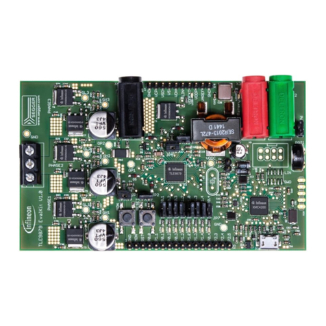
OPTIREG™ PMIC TLF30682QVS01 application
board user manual
About this document
Scope and purpose
The scope of this Application Note is limited to the OPTIREG™ PMIC TLF30682QVS01 Multi-Voltage System
Supply IC. The purpose is to describe the setup, operation, testing and key features of the TLF3068x Application
Board.
Intended audience
This Application Note is intended for users of Infineon’s TLF30682QVS01 Multi-Voltage System Supply IC.
Table of contents
About this document....................................................................................................................... 1
Table of contents............................................................................................................................ 1
1TLF3068x application board overview ...................................................................................... 2
1.1 Functional range .....................................................................................................................................4
1.2 Connectors ..............................................................................................................................................4
2Initial board power up ............................................................................................................ 7
3Board configuration and testing .............................................................................................. 8
3.1 Dynamic load testing ..............................................................................................................................8
3.2 External voltage monitoring ...................................................................................................................8
3.3 Enable functionality..............................................................................................................................10
3.4 Indicator LEDs .......................................................................................................................................10
3.5 Reverse polarity protection ..................................................................................................................11
4Schematic ............................................................................................................................12
5PCB Layout...........................................................................................................................17
Revision history.............................................................................................................................23
