Infineon XENSIV BGT60LTR11AIP User manual

Application Note Please read the Important Notice and Warnings at the end of this document V1.7
www.infineon.com page 1 of 33 2022-08-01
AN608
XENSIV™BGT60LTR11AIP shield
60 GHz radar system platform
Board version 2.0
About this document
Scope and purpose
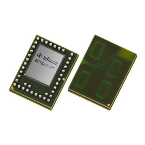
This application note describes the function, circuitry, and performance of the 60 GHz radar BGT60LTR11AIP
shield. The shield provides the supporting circuitry to the on-board BGT60LTR11AIP monolithic microwave
integrated circuit (MMIC) Infineon’s 60 GHz radar chipset with antenna-in-package (AIP). In addition to the
autonomous mode configuration, the shield offers a digital interface for configuration and transfer of the
acquired radar data to a microcontroller board, e.g., Radar Baseboard MCU7.
Intended audience
This document is intended for anyone working with Infineon’s XENSIV™ 60 GHz radar system platform.
Disclaimer
The platform serves as a demonstrator to perform simple motion sensing. The test data in this document
shows typical performance of demonstrator. However, board performance may vary depending on the printed
circuit board (PCB) manufacturer, specific design rules they may impose and components they may use.

Application Note page 2 of 33 V1.7
2022-08-01
XENSIV™ BGT60LTR11AIP shield
60 GHz radar system platform
Introduction
Table of contents
About this document....................................................................................................................... 1
Table of contents............................................................................................................................ 2
1Introduction .......................................................................................................................... 3
1.1 60 GHz radar system platform ................................................................................................................3
1.2 Key features.............................................................................................................................................4
2System specifications ............................................................................................................. 5
2.1 BGT60LTR11AIP shield parameters........................................................................................................5
3Hardware description............................................................................................................. 6
3.1 Overview..................................................................................................................................................6
3.2 BGT60LTR11AIP MMIC.............................................................................................................................7
3.3 Sensor supply..........................................................................................................................................9
3.4 Crystal......................................................................................................................................................9
3.5 External capacitors................................................................................................................................10
3.6 Connectors ............................................................................................................................................11
3.7 EEPROM .................................................................................................................................................12
3.8 LEDs and level shifting ..........................................................................................................................13
3.9 MMIC quad state inputs.........................................................................................................................14
3.10 Layer-stack up and routing...................................................................................................................15
4Radar MMIC settings configuration..........................................................................................16
4.1 Operation mode ....................................................................................................................................16
4.2 Detector threshold ................................................................................................................................18
4.3 Detector hold time ................................................................................................................................19
4.4 Operating frequency .............................................................................................................................20
4.5 Pulse repetition time.............................................................................................................................21
5Autonomous mode operation .................................................................................................22
5.1 Battery-powered operation..................................................................................................................22
5.2 Arduino MKR operation.........................................................................................................................22
6Measurement results.............................................................................................................23
6.1 Radiation pattern ..................................................................................................................................23
6.2 Motion detection area...........................................................................................................................24
6.2.1 Autonomous mode ..........................................................................................................................24
6.2.2 SPI mode and MMIC internal detector.............................................................................................25
6.2.3 SPI mode and motion detection algorithm ....................................................................................26
7Power consumption analysis..................................................................................................27
7.1 Duty cycling ...........................................................................................................................................27
7.2 Adaptive pulse repetition time .............................................................................................................28
8References ...........................................................................................................................31
Revision history.............................................................................................................................32

Application Note page 3 of 33 V1.7
2022-08-01
XENSIV™ BGT60LTR11AIP shield
60 GHz radar system platform
Introduction
1Introduction
1.1 60 GHz radar system platform
The BGT60LTR11AIP MMIC is a fully integrated microwave motion sensor including AIP elements, built-in
motion and direction of motion detectors and a state machine allowing fully autonomous operation of the
MMIC without any external microcontroller. An integrated frequency divider with a Phase-Locked Loop (PLL)
provides VCO frequency stabilization. These features make the small-sized radar solution a compelling, smart
and cost-effective replacement for conventional passive infrared (PIR) sensors in low-power or battery-
powered applications. The MMIC is designed to operate as a Doppler motion sensor in the 60 GHz ISM-band.
The MMIC has four quad-state (QS1-4) input pins that give the performance parameters flexibility even when it
is running in autonomous mode. These pins are used for configuration of the MMIC as explained in section 3.9.
The MMIC supports multiple operation modes, including autonomous mode and SPI mode, which can be
selected via the QS1 pin (see Table 4).
In autonomous mode, the detection threshold (or sensitivity) is set via QS2 pin (see Table 5) and has 16
different levels to fulfill a configurable detection range from 0.5 m up to 7 m with a typical human target Radar
Cross-Section (RCS). The hold time is also configurable in 16 levels via QS3 pin (see Table 6), which allows
detection status holding up to 30 minutes. The device operating frequency can be configured via QS4 pin (see
Table 7) and has 4 different possible frequencies between 61.1 and 61.4 GHz for BGT60LTR11AIP MMIC. In this
mode, the integrated detectors deliver digital output signals indicating motion and direction of motion
(approaching or departing) of a human target.
In SPI mode, a full flexibility regarding radar MMIC parameters configuration e.g. detection threshold, hold time
and operating frequency…, is offered by writing into the MMIC registers the wanted configuration, using an
external microcontroller unit (MCU). In this mode, the integrated detectors, if not disabled, will also deliver
digital outputs indicating motion and direction of motion. If further signal processing is needed, the radar raw
data can be extracted and sampled from BGT60LTR11AIP MMIC and then used for developing customized
algorithms for maximum performance.
The BGT60LTR11AIP shield demonstrates the features of the BGT60LTR11AIP MMIC and gives the user a “plug
and play” radar solution. The shield can also be attached to an Arduino MKR board or an Infineon Radar
Baseboard MCU7. A radar Graphical User Interface (GUI), is available via Infineon Developer Center (IDC) in
order to display and analyze acquired data in time and frequency domain.
BGT60LTR11AIP MMIC BGT60LTR11AIP shield BGT60LTR11AIP Demo
= Radar Baseboard MCU7
+ BGT60LTR11AIP shield
Figure 1 BGT60LTR11AIP shield using BGT60LTR11AIP MMIC

Application Note page 4 of 33 V1.7
2022-08-01
XENSIV™ BGT60LTR11AIP shield
60 GHz radar system platform
Introduction
1.2 Key features
The BGT60LTR11AIP shield is optimized for fast prototyping designs and system integrations, as well as initial
product feature evaluations. In addition, the sensor can be integrated into systems like laptops, tablets, TVs,
speakers etc. to ‘wake’ them up based on motion (or direction of motion) detection, put them to sleep or auto-
lock when no motion is detected for a defined amount of time. This way, it can be a smart power saving feature
for these devices and might also eliminate the need for key-word based activation of systems. Radar sensors
offer the possibility to hide them inside the end product since they operate through non-metallic materials.
Therefore, it enables a seamless integration of technology in our day-to-day lives.
Some key features of the BGT60LTR11AIP shield are as follows:
•Form factor of 20 mm x 6.25 mm for the BGT60LTR11AIP shield
•Features an AIP MMIC of small size (6.7 mm x 3.3 mm x 0.56 mm), thereby eliminating antenna design
complexity at the user end
•Detects motion and direction of movement (approaching or departing) for a human target
•Works standalone (autonomous mode) or also with SPI mode to interface with an external
microcontroller
•Configurable settings like operation mode, detector threshold, detector hold time, operating frequency
•Low-power consumption
•Option to solder onto other PCBs such as Arduino MKR for extra flexibility

Application Note page 5 of 33 V1.7
2022-08-01
XENSIV™ BGT60LTR11AIP shield
60 GHz radar system platform
System specifications
2System specifications
2.1 BGT60LTR11AIP shield parameters
Table 1 lists the various parameters of the BGT60LTR11AIP shield.
Table 1 BGT60LTR11AIP shield specifications
Parameter
Unit
Min.
Typ.
Max.
Comments
System performance
Detection range
m
–
5
7
Typical motion detection range for
human target at low threshold (in
both E and H plane orientation)
Power supply
Supply voltage
V
1.5
3.3
5.0
Current consumption
mA
3.48
At 3.3V supplied via castellated holes
Pulse Repetition Time (PRT) = 500µs
Pulse Width (PW) = 5µs
(LEDs off)
Antenna characteristics (measured)
Antenna type
1 x 1
Antenna-in-Package (AIP)
Horizontal –3 dB beam width
(HPBW)
Degrees
80
At frequency = 61.25 GHz
Elevation –3 dB beam width
(HPBW)
Degrees
80
At frequency = 61.25 GHz

Application Note page 6 of 33 V1.7
2022-08-01
XENSIV™ BGT60LTR11AIP shield
60 GHz radar system platform
Hardware description
3Hardware description
This section presents an overview of the BGT60LTR11AIP shield’s hardware building blocks, such as
BGT60LTR11AIP MMIC, power supply, crystal, and board interfaces.
3.1 Overview
The BGT60LTR11AIP shield is a very small PCB of 20 x 6.25 mm size. Mounted on top of the PCB is a
BGT60LTR11AIP, Infineon’s 60 GHz radar sensor. The antennas are integrated into the chip package; therefore,
the PCB can be manufactured using a standard FR4 laminate. The bottom side of the shield has the connectors
to the Radar Baseboard MCU7 [1] (P1 andP2 in Figure 2). On the top side of the shield, there is a marker that must
be aligned with the marker on the Radar Baseboard MCU7 for correct alignment, as shown in Figure 3.
The castellated holes on the edges of the PCB provide additional access to the detector outputs and power
supply signals of the shield. By using these castellated holes and removing P1 and P2, the BGT60LTR11AIP shield
can be soldered onto other PCBs.
20 mm
6.25 mm
Top view Bottom view
Sensor connectors (P1 and P2)
Castellated holes
Figure 2 Top and bottom views of BGT60LTR11AIP shield
60 GHz Radar System Platform
Markers for
correct
alignment
Figure 3 Markers on Radar Baseboard MCU7 and BGT60LTR11AIP shield for alignment
Note:There is a risk of the connectors wearing out when regularly plugged into and unplugged from the shield. To
prevent this, do not lift the shield on the short side out of the connector. Instead, simply pull on the long side
of the sensor, thereby tilting the short side. This will significantly increase the lifetime of the connectors.

Application Note page 7 of 33 V1.7
2022-08-01
XENSIV™ BGT60LTR11AIP shield
60 GHz radar system platform
Hardware description
38.4 MHz
quartz
EEPROM
LED1
LED2
2
1.8V or 3.3V LDO
1.5V_RF
1.5V_PLL
SPI
IRQ
TDet
PDet
IFI
IFQ
Castellated Holes
5
3.3V
Vin
Vin 1.5V_RF
1.5V_RF
Vin
2
Connectors to Radar Baseboard MCU7
BGT60LTR11AIP MMIC
Figure 4 Block diagram of the BGT60LTR11AIP shield
The block diagram in Figure 4 depicts the configuration of the shield. When the shield is plugged into the Radar
Baseboard MCU7, the MMIC’s supplies are initially deactivated. Only the EEPROM is powered. The MCU reads the
content of the EEPROM’s memory to determine which shield is plugged into the connectors. MMIC’s supplies are
activated only when the shield has been correctly identified.
Communication with the MMIC is mainly performed via a Serial Peripheral Interface (SPI). The BGT_RTSN allows
the MCU to perform a hardware reset of the MMIC. The BGT_SELECT and BGT_RTSN lines of the SPI should be
pulled up with 10 kΩ resistors. The interrupt request (IRQ) line can be used to trigger the MCU when new data
needs to be fetched.
3.2 BGT60LTR11AIP MMIC
The BGT60LTR11AIP MMIC (Figure 5) serves as the main element on the BGT60LTR11AIP shield. The MMIC has
one transmit antennaand one receive antenna integrated into the package. The package dimensions are 6.7 mm
(± 0.1 mm) x 3.3 mm (± 0.1 mm) x 0.56 mm (± 0.05 mm), as illustrated in Figure 6 and Figure 7.
The MMIC has an integrated Voltage Controlled Oscillator (VCO) and Phase Locked Loop (PLL) for high-
frequency signal generation. The transmit section consists of a Medium Power Amplifier (MPA) with
configurable output power, which can be controlled via the SPI.
The chip features a low-noise quadrature receiver stage. The receiver uses a Low Noise Amplifier (LNA) in front
of a quadrature homodyne down-conversion mixer inorder to provide excellent receiver sensitivity. Derivedfrom
the internal VCO signal, an RC Poly-Phase Filter (PPF) generates quadrature LO signals for the quadrature mixer.
The Analog Base Band (ABB) unit consists of an integrated sample and hold circuit for low-power duty-cycled
operation followed by anexternally configurable high-pass filter, a Variable Gain Amplifier (VGA) stage and a low-
pass filter.

Application Note page 8 of 33 V1.7
2022-08-01
XENSIV™ BGT60LTR11AIP shield
60 GHz radar system platform
Hardware description
The integrated target detector circuits in the MMIC indicate the detection of movement in front of the radar and
the direction of movement with two digital signals (BGT_TARGET_DET and BGT_PHASE_DET). See section 3.8 for
more details. The detector circuit offers a user-configurable hold-time for maximum flexibility.
Figure 5 BGT60LTR11AIP MMIC block diagram
Figure 6 Package and pin-signal assignment of the BGT60LTR11AIP MMIC
VDD_RF
A2
QS3
B1 PDET D1
QS4
M1
SPIDO
B6
VTUNE
C1
IFQ K1
TDET E1
PLL_TRIG
G1
VDD_PLL
M2
QS1
M6
VDD_RF
B2
SPIDI
B5
GND M4
GND N4
GND N6
GND N1
GND B3
GND A3
IFQAI
M5
GND B4
GND N3
XOSC_AI
J1
SPIRST_N
A5
GND A6
DIV_O F1
GND A1
IFI L1
XOSC_AO
H1
VDD_PLL
N2
GND A4
QS2
N5
GND M3
SPICLK
C6
SPICS
D6
IFIAO E6
IFIAOX F6
IFIAIX
G6 IFIAI
H6
IFQAO J6
IFQAOX K6
IFQAIX
L6
U1
BGT60LTR11AiP
Xosc_ao
Xosc_ai
QS1
QS2
QS3
QS4
BGT_SCK_1.5_A
BGT_SELECT_1.5_A
BGT_MISO_1.5_A
BGT_MOSI_1.5_A
BGT_RTSN_1.5_A
BGT_PLL_TRIG_1.5
BGT_VTUNE
VTUNE
BGT_TARGET_DET
BGT_DIV
BGT_PHASE_DET
GND
VDD_RF
VDD_PLL
IF1i_P
IF1i_N
IF1q_P
IFI
IFQ
IFQx_PostLPF
IFQ_PostLPF
IFIx_PostLPF
IFI_PostLPF
IF1q_N

Application Note page 9 of 33 V1.7
2022-08-01
XENSIV™ BGT60LTR11AIP shield
60 GHz radar system platform
Hardware description
Top view Side view Bottom view
Figure 7 Top, side, and bottom views of the BGT60LTR11AIP MMIC package –all dimensions in mm
3.3 Sensor supply
Since radar sensors are very sensitive to supply voltage fluctuations or cross-talk between different supply
domains, a low-noise power supply as well as properly decoupled supply rails are vital. The Radar Baseboard
MCU7 provides a low-noise supply. Figure 8 depicts the schematics of the low-pass filters employed to decouple
the supplies of the different power rails in the BGT60LTR11AIP shield. High attenuation of voltage fluctuations in
the MHz regime is provided by ferrite beads (L1, L3 and L5). For example, the SPI which runs up to 50 MHz, induces
voltage fluctuations on the digital domain, which would then couple into and interfere with the analog domain
without the decoupling filters. The ferrite beads are chosen such that they can handle the maximum current of
the sensor with a low DC resistance (below 0.25 Ω) and an inductance as high as possible. The high inductance
will reduce the cut-off frequency of the low-pass filter, which provides better decoupling for lower frequencies.
Figure 8 Schematics of the sensor supply and low-pass filters
3.4 Crystal
The MMIC requires an oscillator source with a stable reference clock providing low phase jitter and low phase
noise. The oscillator is integrated inside the MMIC. This saves current consumption, as crystal oscillators
consume only a few milliamperes (mA) and run continuously. The BGT60LTR11AIP shield uses a 38.4 MHz
crystal oscillator, as shown in Figure 9.
1V5Sensor1V8Sensor L1
MMZ0603S121HT000
Vin VDD_RF
3V3Sensor
1V5_LDO
L3
DNP
GND 2
OUT 1
IN
4
EN
3
EPAD
5
U2
NCP163AMX150TBG
C1
4.7µF C2
100nF
GND
R24
0
C3
4.7µF C4
100nF
GND GND
3V3 L5
MMZ0603S121HT000 GND VDD_PLL
C7
100nF
GND
GND
R23
0
R22
DNP

Application Note page 10 of 33 V1.7
2022-08-01
XENSIV™ BGT60LTR11AIP shield
60 GHz radar system platform
Hardware description
Figure 9 The crystal circuit on the BGT60LTR11AIP shield
3.5 External capacitors
The BGT60LTR11AIP MMIC is duty-cycled and performs a sample and hold (S&H) operation for lower power
consumption. The S&H switches are integrated in chip at each differential IQ mixer output ports. They are
controlled synchronously via the internal state machine. The capacitors between S&H and the high-pass filter
(HPF) are external (Figure 10). C10, C11, C14 and C15 are 5.6 nF capacitors used as “hold”capacitors for the S&H
circuitry. They can be configured for different pulse width settings, as shown in Table 2. C8, C9, C12 and C13 are
the DC blocking (or High Pass) capacitors. They should have a value of 10 nF in order to get a high-pass of 4 Hz
(if internal high pass resistor, RHP = 4 MΩ). It is not recommended to use higher values as it will affect the Analog
Base Band (ABB) settling time. The DC blocking capacitors are important because the mixer output has a
different DC voltage than the internal ABB. In Figure 10 the external hold and high-pass capacitors
are shown for all four branches in the differential IQ configuration.
Figure 10 External capacitors
Table 2 Recommended hold capacitors (C10, C11, C14 and C15) for different pulse widths
Pulse width (µs)
Hold capacitor value (nF)
3
4.7
4
5.6
5 (default)
5.6 (default)
10
15
Charging time of the hold capacitor is limited to the selected pulse width. Shorter pulse widths require
smaller to get it ~ 90% charged during one pulse. Rise-time is controlled by the itself and the
internal mixer output resistance of 300 Ωin each branch.
1 3
2 4
Y1 FH3840024Z
GND
GND
GND
C16
11pF
C17
16pF
GND
Xosc_ai Xosc_ao
IF1i_PIF1q_P IFI_PostLPFIFQ_PostLPF
C8 10nF C9 10nF
GND GND
C10
5.6nF C11
5.6nF
IF1q_N IF1i_N IFIx_PostLPFIFQx_PostLPF
C12 10nF C13 10nF
GND GND
C14
5.6nF C15
5.6nF

Application Note page 11 of 33 V1.7
2022-08-01
XENSIV™ BGT60LTR11AIP shield
60 GHz radar system platform
Hardware description
BGT60LTR11AIP IFIAix
CHP
Chold
IFIAox
S&H switch
Rmixer_out
Pulsed mixer output
(AC + DC
superposed)
RHP
VCC /2
External capacitors
Figure 11 External capacitors for BGT60LTR11AIP
Longer pulse width can have a higher value. This leads to a reduced bandwidth (BW) of the RC filter
(& ). Consequently, there will be a lower baseband noise because of reduced noise folding
bandwidth.
For this RC structure, the low-pass 3dB cutoff frequency
can be calculated under the following
conditions:
= 10% / 90% = S&H ON time = 4µs
Pulse width = 5 µs
=
Or based on the formula:
The high-pass 3dB cutoff frequency
can be calculated under the following conditions:
= 10 nF
=4 M
3.6 Connectors
The BGT60LTR11AIP shield can be connected to an MCU board, like the Radar Baseboard MCU7, with the P1 and
P2 connectors.Visible on the top and bottom side of the PCB are the castellated holes (P3 and P4). TD and PD
pins of the castellated holes correspond to the internal detector outputs of the MMIC.

Application Note page 12 of 33 V1.7
2022-08-01
XENSIV™ BGT60LTR11AIP shield
60 GHz radar system platform
Hardware description
The shield contains two Hirose DF40C-20DP-0.4V connectors, P1 and P2. The corresponding DF40C-20DS-0.4V
connectors are on the Radar Baseboard MCU7. Figure 12 illustrates the pin-out of the Hirose connectors of the
BGT60LTR11AIP shield.
The signal IRQ is connected with a R5 resistor (0 Ω) to the divider output (BGT_DIV) of the MMIC. In SPI pulsed
mode, BGT_DIV generates a signal that acts as an interrupt signal for the MCU to start ADC acquisition. BGT_DIV
could also be used to measure divider frequency.
Bottom view
Sensor connectors (P1 and P2)
Castellated holes
Figure 12 Connectors on the BGT60LTR11AIP shield, and their pin-outs
3.7 EEPROM
The BGT60LTR11AIP shield contains an EEPROM connected via an I2C interface to store data like a board
identifier. Its connections can be seen in Figure 13. This EEPROM contains a descriptor indicating the type of the
shield board and MMIC. This is used by the firmware to communicate properly with the shield.
Figure 13 Connections of the EEPROM
3V3digital
12 D3
Yellow LED 0201
1
122
3
344
5
566
7
788
9
910 10
11
11 12 12
13
13 14 14
15
15 16 16
17
17 18 18
19
19 20 20
21
21
22
22
23
23
24
24
P1
DF40C-20DP-0.4V
1
122
3
344
5
566
7
788
9
910 10
11
11 12 12
13
13 14 14
15
15 16 16
17
17 18 18
19
19 20 20
21
21
22
22
23
23
24
24
P2
DF40C-20DP-0.4V
R17
1k OpenDrain_LEDGND3V3digital1 I2C_SDA I2C_SCL
IFI
IRQ
GND IFQ
BGT_SCK_1.5_A
1V5Sensor BGT_PHASE_DET
BGT_MOSI_1.5_A
1V5Sensor
1V8Sensor VDD_RF
BGT_MISO_1.5_A
BGT_TARGET_DET
1V8Sensor BGT_RTSN_1.5_A GND
1V8Sensor BGT_SELECT_1.5_A
3V3Sensor
GND 3V3digital
3V3Sensor
GND
GND
BGT_DIVIRQ R5 0R
1
2
P3
Header 2
1
2
P4
Header 2
3V3
GND
Target_Det_Out
Phase_Det_Out
1
2
P3
Header 2
1
2
P4
Header 2
3V3
GND
Target_Det_Out
Phase_Det_Out
VCC
A1
SCL
B1
VSS A2
SDA B2
U3
24CW1280T-I/CS0668
GND
3V3digital1
I2C_SDAI2C_SCL
3V3digital1
R11
2k2 R12
2k2

Application Note page 13 of 33 V1.7
2022-08-01
XENSIV™ BGT60LTR11AIP shield
60 GHz radar system platform
Hardware description
3.8 LEDs and level shifting
The shield has two LEDs to indicate the motion detection (green) and target’s direction of motion (red), as
shown in Figure 14, where R1 and R2 are limiting resistors. The digital block within the detector in the MMIC
evaluates and sets the Target detect/Phase detect outputs of the BGT60LTR11AIP MMIC. Target detect (TDet)
output is active low. Phase detect (PDet) output is used to show the direction of the detected target. It is set to
high for approaching targets, otherwise low. The default state for PDet is low.
The outputs from MMIC are at the voltage level of 1.5 V. They are level-shifted to the voltage level of Vin by using
the circuit shown in Figure 14. In the circuit, BGT_TARGET_DET and BGT_PHASE_DET are outputs of MMIC (1.5 V
voltage level). VDD_RF is 1.5 V and Vin is 3.3 V (when connected with Radar Baseboard MCU7).
•When BGT_TARGET_DET is high (1.5 V), NMOS is off (Vgs = 0 V), and Target_Det_Out is 3.3V through the R14
pull-up resistor.
•When BGT_TARGET_DET is low (0 V), NMOS is on (Vgs = 1.5 V), and Target_Det_Out is pulled down to 0 V.
The same applies to the BGT_PHASE_DET signal.
Table 3 LED detection
LED
Mode
Comments
Green
On –target detected
Off –target not detected
Target_Det_Out is an active low signal
Red
On –target departing
Off –target approaching
Phase_Det_Out is an active low signal
Figure 14 Connections of the LEDs and level shifter
VDD_RF
Vin
1
2
6
Q1A
BSD840N
R13
100k R14
10k Target_Det_OutBGT_TARGET_DET
VDD_RF
Vin
5
34
Q1B
BSD840N
R15
100k R16
10k Phase_Det_OutBGT_PHASE_DET
VinVin
R1
1k R2
1k
12
T
Green LED
12
P
Red LED
Phase_Det_OutTarget_Det_Out

Application Note page 14 of 33 V1.7
2022-08-01
XENSIV™ BGT60LTR11AIP shield
60 GHz radar system platform
Hardware description
3.9 MMIC quad state inputs
The BGT60LTR11AIP MMIC has four quad-state inputs QS1-4, used in autonomous mode to set the device
configuration. Figure 15 shows the default settings of these QS pins on the BGT60LTR11AIP shield.
To offer more flexibility, to the autonomous mode, an “Advance mode” is enabled when the BGT_PLL_TRIG pin
is kept “1” during chip boot and QS1 is either GND or OPEN, where BGT_MOSI and BGT_SCK pins are also
sampled to determine the PRT. In addition, pins QS2 and QS3 are evaluated by the ADC and converted in 4-bit
values each before each “mean window”.
QS1BGT_MOSI
QS4
BGT_SCK
QS3
QS2
BGT_PLL_TRIG
Figure 15 MMIC QS1 to QS4 quad state inputs
For more details on the BGT60LTR11AIP MMIC quad state inputs, please refer to the AN625 –User's guide to
BGT60LTR11AIP.

Application Note page 15 of 33 V1.7
2022-08-01
XENSIV™ BGT60LTR11AIP shield
60 GHz radar system platform
Hardware description
3.10 Layer-stack up and routing
The PCB is designed with a 4-layer stack up with standard FR4 material. Figure 16 shows the different layers
and their thicknesses.
Figure 16 PCB layer stack-up in 2D and 3D views
In the routing on the PCB, the VTUNE pin on BGT60LTR11AIP MMIC should be left floating. Any components
added to the line or a long wire connected can result in spurs.

Application Note page 16 of 33 V1.7
2022-08-01
XENSIV™ BGT60LTR11AIP shield
60 GHz radar system platform
Radar MMIC settings configuration
4Radar MMIC settings configuration
The radar MMIC can be configured in both operation modes. In autonomous mode, the sensor configuration
parameters are set via QS pins and external resistors. In SPI mode, the connection to a microcontroller allows
setting the sensor configuration parameters by writing in the internal registers through SPI.
R3
R10R9R6
R18 R19 R20
Threshold
Hold time
Figure 17 QS1 to QS4 schematic and layout connections
4.1 Operation mode
The QS1 pin allows choosing the operation mode of the radar MMIC, as detailed in Table 4.
Table 4 QS1 settings
QS1
Operation mode of the MMIC
PCB configuration
ground
Autonomous continuous wave (CW) mode
J1 = 0 Ω
R3 = DNP*
open
Autonomous pulsed mode
J1 = DNP*
R3 = DNP*
100 kΩ to VDD
SPI mode with external 9.6 MHz clock enabled
J1 = DNP*
R3 = 100 kΩ
VDD (default)
SPI mode
J1 = DNP*
R3 = 0 Ω
*DNP : Do Not Populate/Do Not Place
The DEMO BGT60LTR11AIP comes with the BGT60LTR11AIP shield configured in SPI mode, to enable the radar
MMIC configuration via the firmware running on the Radar Baseboard MCU7 microcontroller.
To make the shield work in autonomous mode, you need to remove R3 resistor as shown in Figure 18.
VDD_RF
GND
VDD_RF
R9
DNP R19
DNP
QS2 QS3
VDD_RFVDD_RF
R3
0R R4
DNP
QS1 QS4
GND GNDGND
VDD_RF
GND
R6
0R
BGT_MOSI_1.5_A BGT_SCK_1.5_A
R27
100K R29
100K
GND GND
VDD_RF VDD_RF
J3
DNP J4
DNP
J1
DNP J2
0R
BGT_PLL_TRIG_1.5
R18
DNP
R20
DNP
R10
0R

Application Note page 17 of 33 V1.7
2022-08-01
XENSIV™ BGT60LTR11AIP shield
60 GHz radar system platform
Radar MMIC settings configuration
Remove R3 for
autonomous mode
Figure 18 Converting the shield to autonomous mode
Note: Once a BGT60LTR11AIP shield is converted to autonomous mode, it should NOT be connected to a
Radar Baseboard MCU7 to change the settings via the GUI. Only, resistor values mentioned in
Table 5 and Table 6 are recommended to be soldered on the shield in order to achieve the desired
settings.

Application Note page 18 of 33 V1.7
2022-08-01
XENSIV™ BGT60LTR11AIP shield
60 GHz radar system platform
Radar MMIC settings configuration
4.2 Detector threshold
The internal detector threshold, is the minimum signal strength that has to be reached to trigger a detection
event. The lower the threshold set, the higher the sensitivity and therefore also the detection range.
Note: To avoid triggering false detections, it would be better to increase the detector threshold, hence
reduce the sensor sensitivity, especially in “noisy”environment.
Autonomous mode
QS2 is used to select the detector threshold value for the autonomous mode. In order to have up to 16
threshold values, the PLL_TRIG should be connected to VDD by removing R6 and placing R18 = 0 Ω. This will put
the MMIC into “Advance mode”. The default QS2 setting on the shield is for threshold 80.
Recommended resistor values for changing the QS2 on the autonomous shield are detailed in Table 5.
Table 5 QS2 settings
Resistors setting
Detector Threshold
(Radar Fusion GUI setting)
Sensitivity
(Radar GUI setting)
R9
R10
10 kΩ
330 Ω
61
15*
10 kΩ
1 kΩ
66
14*
10 kΩ
1.8 kΩ
80
13
10 kΩ
2.7 kΩ
90
12
10 kΩ
3.9 kΩ
112
11
10 kΩ
5.6 kΩ
136
10
10 kΩ
6.8 kΩ
192
9
10 kΩ
8.2 kΩ
248
8
10 kΩ
12 kΩ
320
7
10 kΩ
15 kΩ
284
6
10 kΩ
18 kΩ
480
5
10 kΩ
27 kΩ
640
4
10 kΩ
39 kΩ
896
3
10 kΩ
56 kΩ
1344
2
10 kΩ
100 kΩ
1920
1
10 kΩ
220 kΩ
2560
0
*High sensitivity levels could lead to false detections, are not shown on the Radar GUI settings.
SPI mode
In SPI operation mode, the user can set the internal detector threshold by writing to thrs (Reg2[12:0]) bit fields
of the MMIC SPI registers.

Application Note page 19 of 33 V1.7
2022-08-01
XENSIV™ BGT60LTR11AIP shield
60 GHz radar system platform
Radar MMIC settings configuration
4.3 Detector hold time
The internal detector hold time, is the time for which the internal detector outputs remain active after target
detection.
Autonomous mode
QS3 is used to select the detector hold time value for the autonomous mode. In order to have up to 16 hold
time values, the PLL_TRIG should be connected to VDD by removing R6 and placing R18 = 0 Ω. This will put the
MMIC into “Advance mode”. The default QS3 setting on the shield for the hold time is 1s. Recommended
resistor values for changing the QS3 on the autonomous shield are detailed in Table 6.
Table 6 QS3 settings
Resistors setting
Detector Hold time
R19
R20
10 kΩ
330 Ω
Minimum (16 ms, 32 ms, 64 ms or 128 ms) dep. on PRT
10 kΩ
1 kΩ
500 ms
10 kΩ
1.8 kΩ
1 s
10 kΩ
2.7 kΩ
2 s
10 kΩ
3.9 kΩ
3 s
10 kΩ
5.6 kΩ
5 s
10 kΩ
6.8 kΩ
10 s
10 kΩ
8.2 kΩ
30 s
10 kΩ
12 kΩ
45 s
10 kΩ
15 kΩ
1 min
10 kΩ
18 kΩ
90 s
10 kΩ
27 kΩ
2 min
10 kΩ
39 kΩ
5 min
10 kΩ
56 kΩ
10 min
10 kΩ
100 kΩ
15 min
10 kΩ
220 kΩ
30 min
SPI mode
In SPI operation mode, the user can set the internal detector hold time by writing to hold (Reg10[15:0]) bit fields
of the MMIC SPI registers.

Application Note page 20 of 33 V1.7
2022-08-01
XENSIV™ BGT60LTR11AIP shield
60 GHz radar system platform
Radar MMIC settings configuration
4.4 Operating frequency
Autonomous mode
QS4 is used to set the operating frequency for the MMIC in the 60 GHz ISM band, which is important to meet
worldwide regulation requirements, possible settings are detailed in Table 7.
Table 7 QS4 settings
QS4
Device operating frequency
PCB configuration
ground (default)
61.1 GHz
J2 = 0 Ω
R4 = DNP*
open
61.2 GHz
J2 = DNP*
R4 = DNP*
100 kΩ to VDD
61.3 GHz
J2 = DNP*
R4 = 100 kΩ
VDD
61.4 GHz
J2 = DNP*
R4 = 0 Ω
*DNP : Do Not Populate/Do Not Place
SPI mode
In SPI operation mode, the user can set the device operation frequency by writing to pll_fcw (Reg5[11:0]) bit
fields of the MMIC SPI registers. The BGT60LTR11AIP device operates in the frequency band from 61 GHz to 61.5
GHz.
Note: Please keep a 50 MHz guard band, each side from the band edge, to avoid outside of ISM band
emission.
Note: Sensors operating in close vicinity at the same operating frequency can interfere. To avoid that,
please set different operating frequency for each device, with at list a difference of 12 MHz
Other manuals for XENSIV BGT60LTR11AIP
2
Table of contents
Other Infineon Radar manuals
Popular Radar manuals by other brands

Continental Refrigerator
Continental Refrigerator RightViu Mounting instructions

JUGS Sports
JUGS Sports JUGS Gun owner's manual
Hesai
Hesai Pandar40M user manual
Endress+Hauser
Endress+Hauser Levelflex M FMP41C operating instructions

Endress+Hauser
Endress+Hauser Micropilot FMR66B Brief operating instructions
Endress+Hauser
Endress+Hauser levelflex M FMP 40 operating instructions
