Furuno FAR-3320SW User manual

www.furuno.com
All brand and product names are trademarks, registered trademarks or service marks of their respective holders.
Installation Manual
CHART RADAR
Model FAR-3320W/3220W-BB/
3330SW/3230SW-BB
(Product Name: Marine Radar)
SAFETY INSTRUCTIONS ........................i
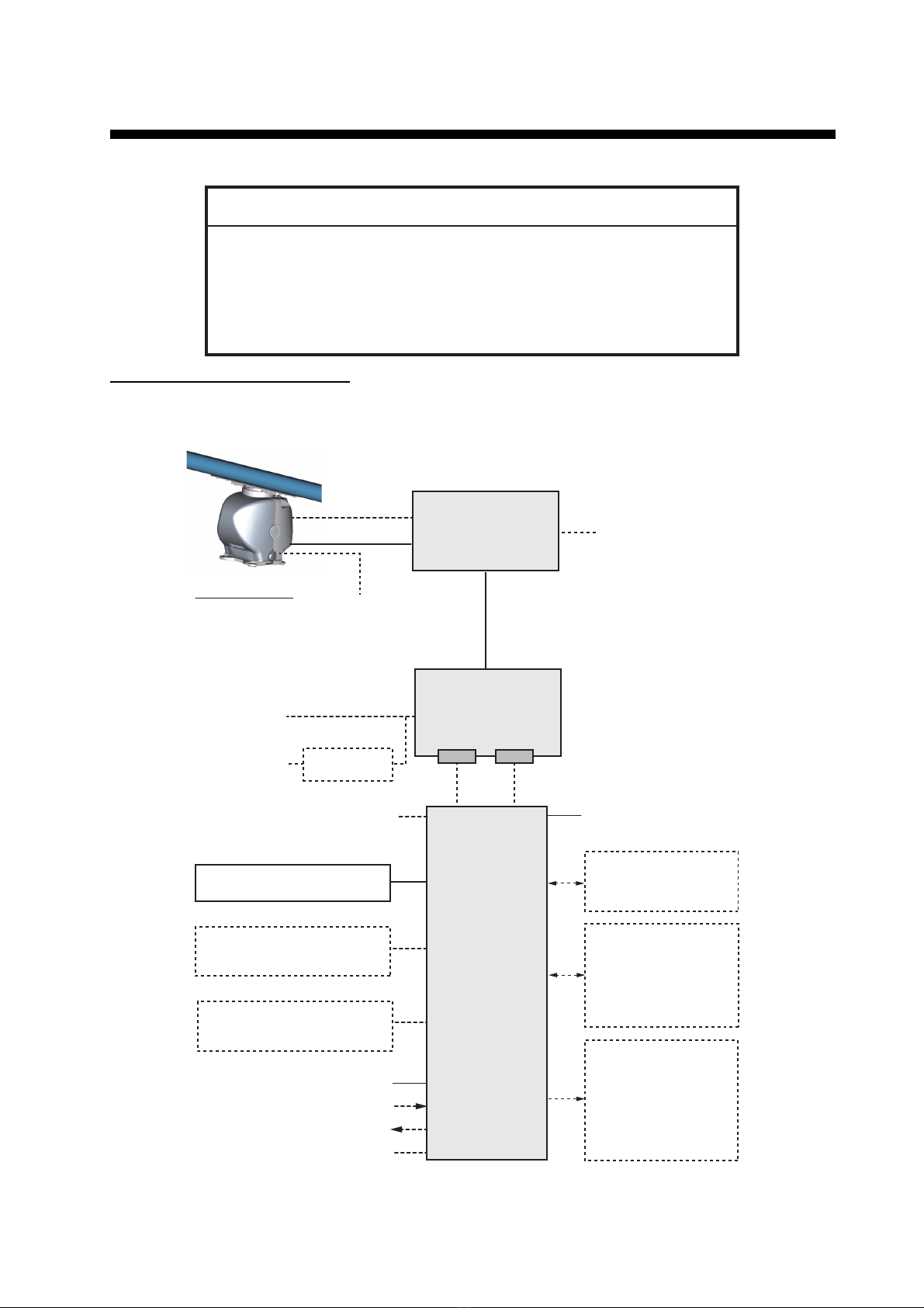
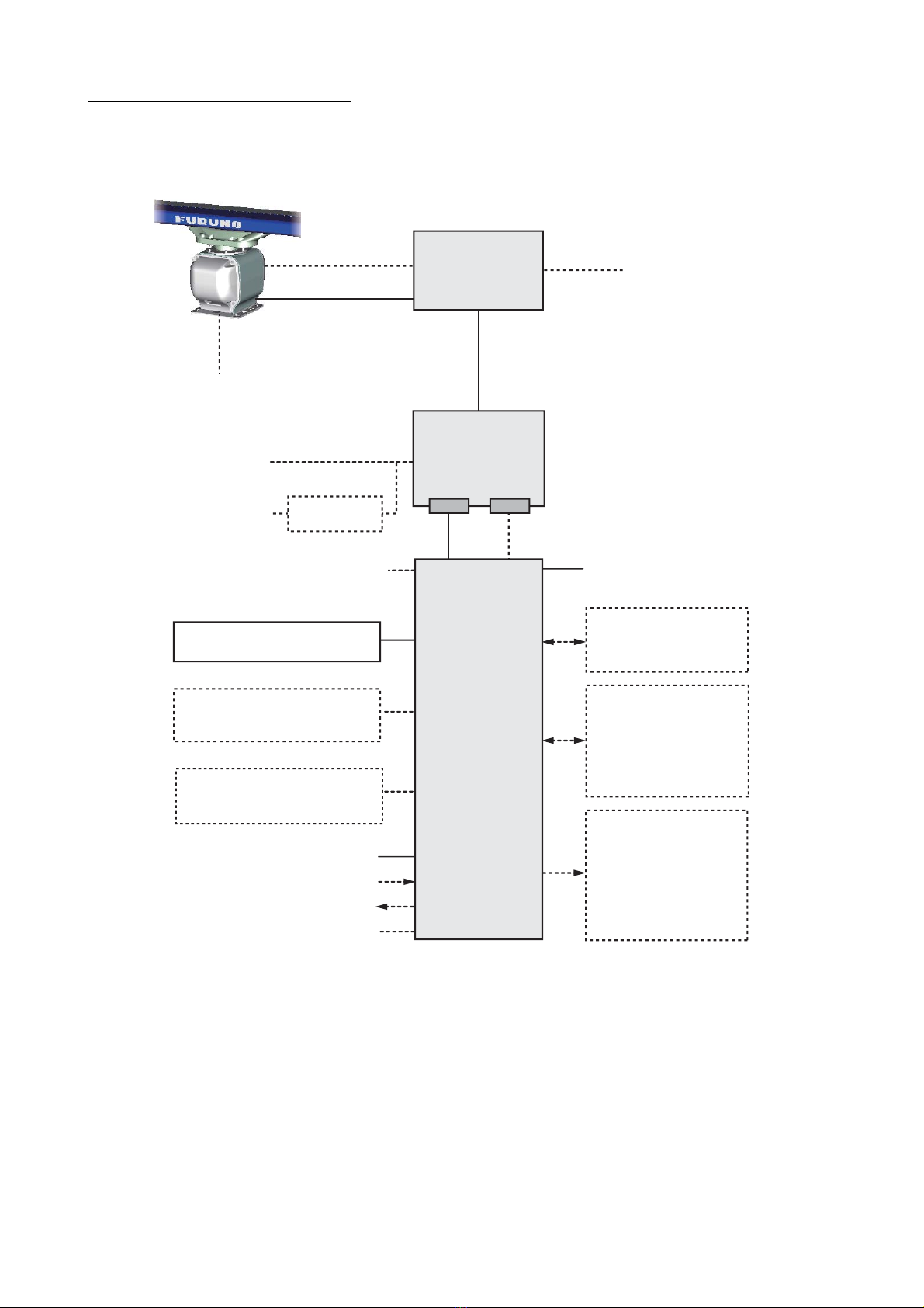
SYSTEM CONFIGURATION ..................iii
EQUIPMENT LIST .................................vii
1. INSTALLATION...............................1-1
1.1 Antenna Unit .......................................1-1
1.2 Transceiver Unit................................1-13
1.3 Monitor Unit.......................................1-13
1.4 Radar Control Unit, Trackball
Control Unit.......................................1-14
1.5 Power Supply Unit ............................1-16
1.6 Processor Unit ..................................1-18
1.7 Sensor Adapters (option)..................1-20
1.8 Intelligent Hub (option)......................1-21
1.9 Switching Hub (option)......................1-22
2. WIRING............................................2-1
2.1 Overview .............................................2-1
2.2 Antenna Unit .......................................2-4
2.3 Transceiver Unit................................2-15
2.4 Processor Unit ..................................2-20
2.5 Power Supply Unit ............................2-31
2.6 Monitor Unit.......................................2-35
2.7 Sensor Adapters (option)..................2-37
2.8 Intelligent HUB (option).....................2-56
2.9 How to Extend the Control Unit
Cable (option) ...................................2-57
3. SETTINGS AND ADJUSTMENTS ..3-1
3.1 How to Access the Radar
Installation Menu.................................3-1
3.2 How to Align the Heading ...................3-1
3.3 How to Adjust the Sweep Timing........3-2
3.4 How to Suppress Main Bang ..............3-2
3.5 Other Settings.....................................3-3
4. INPUT/OUTPUT DATA ...................4-1
4.1 Processor Unit ....................................4-1
4.2 IEC 61162 Sentences .........................4-2
APPENDIX 1 JIS CABLE GUIDE.....AP-1
APPENDIX 2 ROD TERMINALS ......AP-2
APPENDIX 3 DIGITAL
INTERFACE ....................................AP-7
PACKING LISTS ................................. A-1
OUTLINE DRAWINGS ........................ D-1
INTERCONNECTION DIAGRAMS ..... S-1

The paper used in this manual
is elemental chlorine free.
・FURUNO Authorized Distributor/Dealer
9 52 Ashihara cho,
Nishinomiya, 662 8580, JAPAN
A
:
SEP
2014
.
Printed in Japan
All rights reserved.
Pub. No.
IME-36240-A
(
DAMI
)
FAR-3320W
0 0 0 1 7 8 0 3 7 1 0

i
SAFETY INSTRUCTIONS
Mandatory Action
Prohibitive Action
WARNING
Indicates a potentially hazardous situation which, if not avoided,
could result in death or serious injury.
CAUTION
Indicates a potentially hazardous situation which, if not avoided,
can result in minor or moderate injury.
Warning, Caution
WARNING
Radio Frequency Radiation Hazard
* XN20CF: 6.5 ft, XN24CF: 8 ft, SNC36CF: 12 ft
DANGER
Indicates a potentially hazardous situation which, if not avoided,
will result in death or serious injury.
Wear a safety belt and hard hat when working on the antenna unit.
Serious injury or death can result if someone falls from the radar antenna
mast.
DANGER
Model Transceiver Antenna* 100 W/m
2
50 W/m
2
10 W/m
2
FAR-3320W
FAR-3320W-BB
RTR-108
(25 kW)
XN20CF
XN24CF
FAR-3300SW
FAR-3300SW-BB
RTR-109
(30 kW) N/A 0.26 m 2.3 m
0.5 m
0.3 m
The radar antenna emits electromagnetic radio frequency (RF) energy which can be harmful,
particularly to your eyes. Never look directly into the antenna aperture from a close distance while the
radar is in operation or expose yourself to the transmitting antenna at a close distance. Distances at
which RF radiation level of 100, 50 and 10 W/m
2
are given in the table below.
If the antenna unit is installed at a close distance in front of the wheel house, your administration may
require halt of transmission within a certain sector of antenna revolution. See the installation manual
for how to manage blind sectors.
The installer of the equipment must read the applicable safety instructions before attempting to install
the equipment.
SN36CF
1.2 m
0.9 m
5.5 m
4.0 m

SAFETY INSTRUCTIONS
ii
CAUTION
Observe the following compass safe
distances to prevent deviation of a mag-
netic compass:
Note: For more information, please refer to IMO
SN/Circ.271 “Guidelines for the installa-
tion of shipborne radar equipment.”
Do not open the equipment
unless totally familiar with
electrical circuits and
service manual.
Only qualified personnel are
allowed to work inside the
equipment.
WARNING
ELECTRICAL
SHOCK
HAZARD
Construct a suitable service
platform from which to install the
antenna unit.
Serious injury or death can result if
someone falls from the radar antenna
mast.
Turn off the power at the mains
switchboard before beginning the
installation.
Fire, electrical shock or serious injury
can result if the power is left on or is
applied while the equipment is being
installed.
Be sure that the power supply is
compatible with the voltage rating
of the equipment.
Connection of an incorrect power
supply can cause fire or damage the
equipment.
Use only the specified power
cable.
Fire or damage to the equipment can
result if a different cable is used.
Do not install the monitor unit,
processor unit, transceiver unit,
power supply unit or control unit
in a dusty environment, orone
where the units may get wet from
rain or water splash.
Dust or water in the units can result in
fire, electrical shock, or damage to
the equipment.
Attach protective earth securely to
the ship's body.
The protective earth (grounding) is
required for the AC power supply to
prevent electrical shock.
Transceiver Unit
(RTR-108)
2.00 m 1.25 m
4.50 m 2.90 m
Antenna Unit
(FAR-3320W)
Standard
compass
1.90 m 1.20 m
Antenna Unit
(FAR-3330SW) 1.55 m 0.95 m
Monitor Unit
(MU-231) 0.85 m 0.55 m
Radar Control
Unit (RCU-025) 0.30 m 0.30 m
Trackball Control
Unit (RCU-026) 0.30 m 0.30 m
Steering
compass
Intelligent HUB
(HUB-3000)
2.05 m 1.35 m
1.20 m 0.75 m
Processor Unit
(EC-3000) 2.40 m 1.55 m
Sensor Adapter
(MC-3000S)
0.75 m 0.50 m
Sensor Adapter
(MC-3010A0)
Sensor Adapter
(MC-3020D)
Sensor Adapter
(MC-3030D)
1.05 m 0.70 m
0.90 m 0.60 m
Switching HUB
(HUB-100) 1.00 m 0.60 m
Power Supply
Unit (PSU-014/
PSU-015)
2.20 m 1.40 m
Transceiver Unit
(RTR-109)
Junction Box
(RJB-001)
1.10 m 0.70 m

iii
SYSTEM CONFIGURATION
FAR-3320W, FAR-3220W-BB
Basic configuration shown with solid line.
See page v for footnotes.
NOTICE
The radar(s) must be interconnected to the following type approved sensors:
EPFS meeting the requirements of the IMO resolution MSC.112(73).
Gyrocompass meeting the requirements of the IMO resolution A.424(XI).
SDME meeting the requirements of IMO resolution MSC.96(72).
The radar may be interconnected via HUB-3000 to other FURUNO processing
units having approved LAN ports.
100-115/220-230 VAC
1ø, 50-60 Hz
PSU-014
POWER SUPPLY
UNIT
EC-3000
PROCESSOR
UNIT
Serial 1, 2
IEC 61162-2
(Gyrocompass
1
, AIS)
Serial 3 - 7
IEC 61162-1
(EPFS
2
(Navigator),
SDME
(Speed Log),
Echo Sounder, Wind,
Alarm
5
, Navtex, etc.)
Digital Out 1 - 6
5
1: System Fail
2: Power Fail
3: Normal Close 1
4: Normal Close 2
5: Normal Open 1
6: Normal Open 2
100-230 VAC
1ø, 50-60 Hz
Transformer
RU-1803
440 VAC
1ø, 50-60 Hz
Sensor Adapter
4
or Switching HUB
HUB-100
Radar Control Unit RCU-025
Trackball Control Unit RCU-026
ECDIS Control Unit RCU-024
Radar Control Unit RCU-025
Trackball Control Unit RCU-026
Monitor Unit MU-231
3
Digital In (ACK IN)
VDR
Intelligent HubHUB-3000
Sub monitor
LAN Serial
Select one
Select one
ECDIS Control Unit RCU-024
Radar Control Unit RCU-025
Trackball Control Unit RCU-026
Select one
100-115/220-230 VAC
1ø, 50-60 Hz
(for de-icer)
TRANSCEIVER UNIT
RTR-108
Antenna cable
ANTENNA UNIT
w/ Perf. Monit. PM-32A
XN20CF-RSB-130
XN24CF-RSB-130
Waveguide

SYSTEM CONFIGURATION
iv
FAR-3330SW, FAR-3230SW-BB
Basic configuration shown with solid line.
See the next page for footnotes.
100-115/220-230 VAC
1ø, 50-60 Hz
Serial 1, 2
IEC 61162-2
(Gyrocompass
1
, AIS)
Serial 3 - 7
IEC 61162-1
(EPFS
2
(Navigator),
SDME
(Speed Log),
Echo Sounder, Wind,
Alarm
5
Navtex, etc.)
Digital Out 1 - 6
5
1: System Fail
2: Power Fail
3: Normal Close 1
4: Normal Close 2
5: Normal Open 1
6: Normal Open 2
100-230 VAC
1ø, 50-60 Hz
Transformer
RU-1803
440 VAC
1ø, 50-60 Hz
Sensor Adapter
4
or Switching HUB
HUB-100
Radar Control Unit RCU-025
Trackball Control Unit RCU-026
ECDIS Control Unit RCU-024
Radar Control Unit RCU-025
Trackball Control Unit RCU-026
Monitor Unit MU-231
3
Digital In (ACK IN)
VDR
Intelligent HubHUB-3000
ANTENNA UNIT (w/Performance Monitor PM-52A)
SN36CF-RSB-131
Sub monitor
EC-3000
PROCESSOR
UNIT
LAN Serial
PSU-014 or PSU-015
POWER SUPPLY
UNIT
Select one
Select one
ECDIS Control Unit RCU-024
Radar Control Unit RCU-025
Trackball Control Unit RCU-026
Select one
TRANSCEIVER
UNIT
RTR-109
100-115/220-230 VAC
1ø, 50-60 Hz
(for de-icer)
Antenna cable
Coaxial cable
PSU-014: 24 rpm antenna unit
PSU-015: 42 rpm antenna unit

SYSTEM CONFIGURATION
v
Category of units:
Antenna unit: Exposed to weather
Other units: Protected from the weather
Notes
1) The gyrocompass must be type approved for compliance with IMO resolution A.424(XI) (and/
or resolution A.821(19) for installation on HSC). The gyrocompass must also have an update
rate that is adequate for the ship’s rate of turn. The update rate must be better than 40 Hz
(HSC) or 20 Hz (conventional vessel).
2) The EPFS must be type approved for compliance with IMO resolution MSC.96(72).
3) The monitor MU-231 has been approved by the IMO for CAT 1C and CAT 1HC. If a different
monitor is to be used on IMO vessels, its effective diameter must meet the applicable Category
requirements. (Monitor Unit MU-190 is optionally available for the blackbox models and it is
approved by the IMO for CAT 2C and CAT 2HC.)
4) The sensor adapters are Control Serial MC-3000S, Analog IN MC-3010A,
Digital IN MC-3020D and Digital OUT MC-3030D.
5) Characteristics of contact output for Alarm:
• (Load current) 250 mA
• (Polarity) Normally Open: 2 ports, Normally Close: 2 ports
• Serial I/O for alarm is also possible, which complies with IEC 61162-1.

SYSTEM CONFIGURATION
vi
Interswitch connection
When multiple radars are used, connect, to the EC-3000, the HUB-3000 to the LAN1 port, and
HUB-100 to the LAN2 port. This configuration lets each radar be a standalone radar in case of
HUB malfunction.
Radar component configurations
RADAR
MODEL
ANTENNA
UNIT
TRANSCEIVER
UNIT
POWER SUPPLY
UNIT
FAR-3x10
FAR-3x20
XN12CF-RSB-128
XN20CF-RSB-128
XN24CF-RSB-128
RTR-105
PSU-014
RTR-106
FAR-3x20W XN20CF-RSB-130
XN24CF-RSB-130 RTR-108
FAR-3x30S SN36CF-RSB-129 RTR-107 PSU-014
PSU-015
FAR-3x30SW SN36CF-RSB-131 RTR-109
FAR-3x30S-SSD SN36CF-RSB-133 RTR-111 PSU-016
PSU-018
EC-3000
PROCESSOR
UNIT
Radar Control Unit RCU-025
Trackball Control Unit RCU-026
ECDIS Control Unit RCU-024
Radar Control Unit RCU-025
Trackball Control Unit RCU-026
(Max. 2)
Select one
Select one
Serial 1,2 (IEC 61162-2)
Serial 3-7 (IEC 61162-1)
VDR
Switching
HUB
HUB-100
Intelligent HUB
HUB-3000
POWER SUPPLY UNIT
TRANSCEIVER UNIT
LAN3
LAN1
LAN2
100-230 VAC
1ø, 50-60 Hz
100-115/220-230 VAC
1ø, 50-60 Hz (for de-icer)
Sub monitor
Gateway network
equipment
(Radar, ECDIS, etc.)
Serial8
LAN2
- Digital Out×6
(Power fail/system
fail/NO×2.NC×2)
- Digital in (ACK in)
Radar Control Unit RCU-025
Trackball Control Unit RCU-026
ECDIS Control Unit RCU-024
Radar Control Unit RCU-025
Trackball Control Unit RCU-026
(Max. 2)
Select one
Select one
Serial 1,2 (IEC 61162-2)
Serial 3-7 (IEC 61162-1)
VDR
- Digital Out×6
(Power fail/system
fail/NO×2.NC×2)
- Digital in (ACK in)
Monitor Unit MU-190 MU-231
(or equivalent for -BB model)
EC-3000
PROCESSOR
UNIT
LAN3 Serial8
LAN1
100-115/220-230 VAC
1ø, 50-60 Hz 100-115/220-230 VAC
1ø, 50-60 Hz
ANTENNA UNIT
Solid lines indicate
standard supply
equipment.
Dashed lines indicate
optional or local supply
equipment.
Sensor Adapter
MC-3000S
Serial
interface
Sensor Adapter
MC-3010A
Sensor Adapter
MC-3020D
Sensor Adapter
MC-3030D
Analog
interface
Digital in
interface
Digital out
interface
100-230 VAC
1ø, 50-60 Hz
100-115/220-230 VAC
1ø, 50-60 Hz (for de-icer)
Sub Monitor
POWER SUPPLY UNIT
ANTENNA UNIT
TRANSCEIVER UNIT
Monitor Unit MU-190 MU-231
(or equivalent for -BB model)

vii
EQUIPMENT LIST
Standard supply for FAR-3320W/FAR-3220W-BB
Name Type Code No. Qty Remarks
Antenna Unit XN20CF-RSB-130 - Select
one
6.5 ft
XN24CF-RSB-130 - 8 ft
Transceiver Unit RTR-108 - 1
Processor Unit EC-3000 - 1
Monitor Unit MU-231 - 1
Control Unit RCU-025 - Select
one
Standard type
RCU-026 - Trackball type
Power Supply Unit PSU-014 - 1
Installation Materials CP03-35201 001-249-860 1 For radiator
CP03-35500[15M] 000-024-096 Select
one
For antenna unit, 15 m
CP03-35510[30M] 000-024-097 For antenna unit, 30 m
CP03-35520[40M] 000-024-098 For antenna unit, 40 m
CP03-35530[50M] 000-024-099 For antenna unit, 50 m
CP03-36001 001-300-990 1 For transceiver unit
CP03-35301 001-249-770 1 For PSU-014
CP24-02120 000-024-925 1 For EC-3000
CP24-02200 000-022-508 1 For RCU-025
CP24-02300 000-022-509 1 For RCU-026
CP03-16400 000-086-743 Select
one
Waveguide inst., 10 m
w/CP03-16411
CP03-16410 000-086-744 Waveguide inst., 20 m
w/CP03-16411
CP03-16420 000-086-745 Waveguide inst., 30 m
w/CP03-16411
CP03-16430 000-086-746 Waveguide inst., 50 m
w/CP03-16411
CP03-35901 001-300-540 Select
one
With de-icer
CP03-35902 001-300-550 No de-icer
Accessories FP24-00603 001-285-760 1 For EC-3000
FP24-00701 001-170-820 1 For RCU-025
FP24-00801 001-170-920 1 For RCU-026
Spare Parts SP24-00601 001-170-660 1 For EC-3000
Fuse: FGMB 125V 10A
PBF (000-157-470-10,
3 pcs.)
SP24-00602 001-170-670 1 For EC-3000
Fuse: FGMB 250V 5A
PBF (000-157-570-10,
3 pcs.)
SP03-17641 001-249-740 1 For PSU-014
Fuse: FGBO 250V 7A
PBF (000-178-084-10,
2 pcs.)
Hoist X-Band
Antenna Instructions
C32-01302-* 1

EQUIPMENT LIST
viii
Standard supply for FAR-3330SW/FAR-3230SW-BB
Name Type Code No. Qty Remarks
Antenna Unit SN36CF-RSB-131 - 1
Transceiver Unit RTR-109 - 1
Processor Unit EC-3000 - 1
Monitor Unit MU-231 - 1 For FAR-3330SW
Control Unit RCU-025 - Select
one
RCU-026 -
Power Supply Unit PSU-014 - 1 24 rpm
PSU-015 - 1 42 rpm
Installation Materials CP03-35202 001-249-880 1 For radiator
CP03-35500[15M] 000-024-096 Select
one
For antenna unit, 15 m
CP03-35510[30M] 000-024-097 For antenna unit, 30 m
CP03-35520[40M] 000-024-098 For antenna unit, 40 m
CP03-35530[50M] 000-024-099 For antenna unit, 50 m
CP03-36001 001-300-990 1 For transceiver unit
CP03-35301 001-249-770 1 For PSU-014, PSU-015
CP03-36300 000-025-573 Select
one
Coax cable, 20 m
CP03-36310 000-025-574 Coax cable, 30 m
CP24-02120 000-024-925 1 For EC-3000
CP24-02200 000-022-508 1 For RCU-025
CP24-02300 000-022-509 1 For RCU-026
CP03-36101 001-301-200 Select
one
With de-icer
CP03-36102 001-301-360 No de-icer
Accessories FP24-00603 001-285-760 1 For EC-3000
FP24-00701 001-170-820 1 For RCU-025
FP24-00801 001-170-920 1 For RCU-026
Spare Parts SP24-00601 001-170-660 1 For EC-3000
Fuse: FGMB 125V 10A
PBF (000-157-470-10,
3 pcs.)
SP24-00602 001-170-670 1 For EC-3000
Fuse: FGMB 250V 5A
PBF (000-157-570-10,
3 pcs.)
SP03-17641 001-249-740 1 For PSU-014
Fuse: FGBO 250V 7A
PBF (000-178-084-10,
2 pcs.)
SP03-17651 001-249-750 1 For PSU-015
Fuse: FGBO 250V 7A
PBF (000-178-084-10,
2 pcs.), FGBO 250V 3A
PBF (000-155-841-10,
2 pcs.)
Hoist S-Band
Antenna Instructions
C32-01303-* 1

EQUIPMENT LIST
ix
Optional supply
Name Type Code No. Remarks
Sensor
Adapter
MC-3000S - Serial type
MC-3010A - Analog IN
MC-3020D - Digital IN
MC-3030D - Digital OUT
De-icer Kit OP03-231 001-305-060
De-icer Kit OP03-232 001-305-070
Prog. Inst. Soft-
ware
OP03-230 001-285-780 DVD-R
Switching HUB HUB-100 -
Intelligent HUB HUB-3000 -
Control Unit RCU-024 - ECDIS standard type
RCU-026 - Trackball type
Monitor Unit MU-190 - For FAR-3220W-BB,
FAR-3230SW-BB
MU-231 -
Hanger OP26-15 001-116-730 For Monitor Unit MU-231
Hood Assembly OP26-16 001-116-740
Flush Mount Kit OP26-17 001-116-750
Hanger OP26-5 000-016-270 For Monitor Unit MU-190
(for blackbox models)
Hood Assembly OP26-6 001-080-930
Flush Mount Kit OP26-12 001-116-280
Dust Cover 03-163-7271 001-121-230-10
Cable OP24-32 001-188-300 USB cable between processor unit
and control unit
Terminal Opener OP24-33 001-188-850
Transformer
Unit
RU-1803 -
RU-3305-0 -
RU-5693 -
RU-6522 -
RU-5466-1 -
Rectifier RU-3424 - AC220V
RU-1746B-2 -
LAN Cable Assy. MOD-Z072-050+ 001-167-890-10
AC/DC Power
Supply Unit
PR-240 000-013-632
Installation
Materials
CP03-28900(10M) 000-082-658 LAN cable for sensor adapter
CP03-28910(20M) 000-082-659
CP03-28920(30M) 000-082-660
Installation
Materials
CP24-02900(10M) 001-208-050 LAN cable for HUB-3000
CP24-02910(20M) 001-208-060 LAN cable for HUB-3000
CP24-02920(30M) 001-208-070 LAN cable for HUB-3000
Thru-deck Cable
Gland
CP03-00702 008-197-350 For FAR-3330SW/3230SW-BB
Cable Clamping
Fixture
03-011-3228 001-074-670-10 For FAR-3330SW/3230SW-BB
Connector CP03-28901 008-542-460
Cable Assy. DVI-BNCX5-L2000 001-204-150 For EC-3000
Crimping Tool CRIMPFOX 10S 001-206-920 For sensor adapters

EQUIPMENT LIST
x
Cable Assy. DVI-D/D S-LINK 5M 001-132-960-10 Between processor unit and
control unit, 5 m
DVI-D/D S-LINK 10M 001-133-980-10 Between processor unit and
control unit, 10 m
Cable Assy. DSUB9P-X2-L5M 001-188-260 Brilliance control cable for
MU-231, 5 m
DSUB9P-X2-L10M 001-188-270 Brilliance control cable for
MU-231, 10 m
Cable Assy. DSUB9P-X2-L5M-
WP
001-207-890 Brilliance control cable for
MU-231, 5 m, IPX2 std.
DSUB9P-X2-L10M-
WP
001-207-900 Brilliance control cable for
MU-231, 5 m, IPX2 std.
Cable Assy. DSUB9P-X2-A-L5M 001-252-580 For connection with
MU-2x1CE HD monitor
DSUB9P-X2-A-L10M 001-252-590 For connection with
MU-2x1CE HD monitor
Cable Assy. DVI-BNCX5-L2000 001-204-150 For connecting a VDR
Cable Assy. 6TPSH-XH12X2-
L5.0SP1
001-186-260-10 For RCU-025, 5 m
6TPSH-XH12X2-
L10SP1
001-186-270-10 For RCU-025, 10 m
6TPSH-XH12X2-
L20SP1
001-186-280-10 For RCU-025, 20 m
6TPSH-XH12X2-
30SP1
001-186-290-10 For RCU-025, 30 m
6TPSH-XH12X2-
L5.0SP2
001-186-310-10 For RCU-026, 5 m
6TPSH-XH12X2-
L10SP2
001-186-320-10 For RCU-026, 10 m
6TPSH-XH12X2-
L20SP2
001-186-330-10 For RCU-026, 20 m
6TPSH-XH12X2-
L30SP2
001-186-340-10 For RCU-026, 30 m
Cable MC1.5-W-L600 001-187-470-10 Between sensor adapters, 6 m
MC1.5-W-L1000 001-187-480-10 Between sensor adapters, 10 m
MC1.5-W-L2000 001-187-490-10 Between sensor adapters, 20 m
MC1.5-W-L3000 001-187-500-10 Between sensor adapters, 30 m
Junction Box RJB-001
Spare Parts SP24-00801 001-235-320 For HUB-3000
Waveguide Twist RWA-1050 C-109 001-304-660 For FAR-3320W
Rectangular Guide
Clamp
OP03-148 008-477-540
FR-9 Rect. Guide
Tool
OP03-123 008-448-870
FR-9 Flare Tool R4KG5549 000-151-798
FR-9Termination FR-9-00 001-102-740
Waveguide Drain 03-009-0360-0 300-903-600
H-type Waveguide
Clamp
CP03-00600-W 008-198-420
E-Bend
Waveguide
RWA-1030 B-107 001-304-640
Name Type Code No. Remarks

EQUIPMENT LIST
xi
About the category sticker
This radar meets the requirements in IEC62388 (Marine naviga-
tion and radiocommunication equipment and systems-Shipborne
radar-Performance requirements, method of testing and required
test results).
Check the appropriate box on the sticker which is pre-attached to
the processor unit, according to your radar’s specification. Refer
to the table shown below to confirm your category.
Operator’s Manual OME-36160-* English
OMJ-36160-* Japanese
Magnetron Re-
placement Instruc-
tion Manual
E32-01306-* English
J32-01306-* Japanese
Category Radar type ANT. rotation speed
CAT 1C FAR/3320W/3330SW 24 rpm
CAT 1HC Same models as above 42 rpm
CAT 2C FAR/3320W(-BB)/3330SW(-BB) 24 rpm
CAT 2HC Same models as above 42 rpm
Name Type Code No. Remarks
Comply with MSC.192(79)
CAT 1C
CAT 2C
CAT 1HC
CAT 2HC
Sticker for category

EQUIPMENT LIST
xii
This page is intentionally left blank.

1-1
1. INSTALLATION
1.1 Antenna Unit
1.1.1 Installation considerations
• The antenna unit is generally installed either on top of the wheelhouse or on the ra-
dar mast, on a suitable platform. Locate the antenna unit in an elevated position to
permit maximum target visibility.
• A line of sight from the antenna unit to the bow of the ship must hit the surface of
the sea in not more than 500 m or twice the ship’s length, depending whichever val-
ue is smaller, for all load and trim conditions.
• Install the antenna unit so that any blind sectors caused by objects (mast, etc.) are
kept to a minimum. A blind sector must not exist in arc of the horizon from right
ahead to 22.5° aft of the beam to either side (see the figure below). Also, individual
blind sectors of more than 5°, or the total arc of both blind sectors of more than 20°,
must not occur in the remaining arc (Figure 2). Note that any two blind sectors sep-
arated by 3° or less are regarded as one sector.
• Do not install the antenna where extreme winds may strike the port and starboard
sides of the antenna.
NOTICE
Do not apply paint, anti-corrosive sealant or contact
spray to coating or plastic parts of the equipment.
Those items contain organic solvents that can damage
coating and plastic parts, especially plastic connectors.
less than 500 m or twice the ship's length
Figure 1 Figure 2
less than 3°
22.5°
22.5°
270° 90°
a, b, c: less than 5° respectively
a+b+c+: less than 20°
a, b, c: less than 5° respectively
a+b+c+: less than 20°

1. INSTALLATION
1-2
• Install the antenna unit away from interfer-
ing high-power energy sources and TX ra-
dio antennas.
• Keep the lower edge of the antenna unit
above the safety rail by at least 500 mm.
• Install two antenna units as shown in the
right figure.
• No funnel, mast or derrick shall be within
the vertical beamwidth of the antenna unit
in the bow direction, especially zero degree
±5°, to prevent blind sectors and false ech-
oes on the radar picture.
• It is rarely possible to place the antenna
unit where a completely clear view in all directions is available. Therefore, deter-
mine the angular width and relative bearing of any shadow sectors for their influ-
ence on the radar at the first opportunity after fitting.
• Locate an EPFS antenna clear of the antenna unit to prevent interference to the
EPFS. A separation of more than two meters is recommended.
• A magnetic compass will be affected if the antenna unit is placed too close to the
compass. Observe the compass safe distances on page ii to prevent interference
to a magnetic compass.
• Do not paint the radiator aperture, to ensure proper emission of the radar waves.
• Ground the unit with the ground wire (sup-
plied).
• An antenna switch is provided on the chassis
of the X-band antenna to stop the antenna.
Make sure the mounting location provides
easy access to the switch.
• Deposits and fumes from a funnel or other ex-
haust vent can affect the aerial performance and hot gases may distort the radiator
portion. Do not install the antenna unit where the temperature is more than 55°C.
• Leave sufficient space around the unit for maintenance and servicing. See the an-
tenna unit outline drawing for recommended maintenance space.
• If it is necessary to lay
down the radiator before
fastening it to the antenna
unit, lay it down with the
waveguide up, to prevent
damage to the cylinder that
surrounds the waveguide.
Note: For more information,
please refer to IMO SN/
Circ.271 “Guidelines for the installation of shipborne radar equipment.”
more than 20°
more than 1 m
Lay down radiator
with waveguide
facing upward.
Waveguide
Waveguide
Cylinder
Cylinder

1. INSTALLATION
1-3
1.1.2 How to assemble, mount the antenna unit for FAR-3320W,
FAR-3220W-BB
How to assemble the antenna unit
The antenna unit consists of the antenna radiator and the antenna unit chassis, and
they are packed separately. Fasten the antenna radiator to the antenna unit chassis
as follows:
1. Remove the protective waveguide cap and the gasket beneath the waveguide cap
from the waveguide on the radiator bracket.
2. Coat the hatched area shown below with the supplied marine sealant.
3. Coat the threads of six hex bolts (M8×50, supplied) with the supplied marine seal-
ant. Set the radiator to the radiator bracket.
Remove this cap and the RJ
gasket beneath it BEFORE
fastening the radiator. RJ gasket
Marine
sealant
Do not apply the sealant to these locations.
Radiator
bracket
FRONT
REAR
Radiator
bracket

1. INSTALLATION
1-4
4. Fasten the antenna radiator to the radiator bracket with the six sets of hex bolts,
flat washers (2 pcs.) and gaskets. Fasten the bolts in the order shown below.
The torque must 15.0 N•m.
5. Coat the screws fixed at step 4 with marine
sealant (supplied) as shown in the right fig-
ure.
How to fasten the antenna unit to the mounting platform
The antenna unit may be assembled before hoisting it to the mounting platform. Hoist
the antenna referring to the illustration below and "FAR-3xx0 Series X-band Antenna
Unit Installation Notices," issued separately.
Hex bolt
Flat washer
Gasket
Flat washer
Coat with
marine sealant.
Coat with
marine
sealant.
Do one of the following to hoist the antenna unit.
How to Hoist the Antenna Unit
Pass belt sling around
radiator bracket.
Radiator bracket
Radiator bracket
Method 2
Bow side UP
Fasten belt sling to a shackle, pass belt sling
around antenna support and fasten other end
of belt sling to other shackle.
Shackle
(left, right)
Shackle
(left, right)
Lifting fixture
(ø20)
Lifting fixture
(ø20)
Belt sling
Belt sling
Method 1
Belt sling
Set belt slings to
radiator bracket.

1. INSTALLATION
1-5
1. Construct a suitable mounting platform referring to the outline drawing at the end
of this manual.
2. Referring to the outline drawing, drill four mounting holes in the mounting platform.
3. Place the antenna unit on the platform, then orient the unit so the bow mark on its
base is facing the ship’s bow.
4. Fasten the antenna unit to the mounting platform with four sets of M12×60 hex
bolts, nuts, flat washers, seal washers and spring washers. Insert the bolts from
the topside of the platform. The torque must be 49 N•m. Insert the bolts from the
top of the platform. DO NOT insert the bolts from the underside of the plat-
form. The cover cannot be opened.
5. Using a hex bolt (M6×25), nut (M6) and flat washer (M6), establish the ground sys-
tem on the mounting platform as shown in the figure on the next page. The loca-
tion must be within 340 mm of the ground terminal on the antenna unit. Connect
the ground wire (RW-4747, 340 mm, supplied) between the grounding point and
ground terminal on the antenna unit. Coat the hardware of the ground system with
marine sealant (supplied).
Bow mark ()
FRONT
FRONT

1. INSTALLATION
1-6
Hex bolt
OR
Ground wire
Welding
Hex nut
Arrange grounding point as close as possible to antenna unit.
Hex
bolt
Flat washer
Hex nut
Spring washer
Flat washer Flat
washer
Spring washer
Ground
terminal
Ground wire
Coat with marine sealant.
Flat washer
Seal washer
(Torque: 49 N•m)
Flat washer
Spring washer
Fasten ground wire
then coat with marine
sealant.
Ground wire
Antenna chassis
Nut
Coat with
marine
sealant.
This manual suits for next models
3
Table of contents
Other Furuno Radar manuals

Furuno
Furuno DRS6A User manual

Furuno
Furuno DRS6A-NXT User manual

Furuno
Furuno WR2120 User manual

Furuno
Furuno FR-2105 User manual

Furuno
Furuno FRS1000 Operator's manual

Furuno
Furuno FR-1500 MARK-3 User manual

Furuno
Furuno FAR2137S/12 User manual

Furuno
Furuno DRS12AX X-Class User manual

Furuno
Furuno WR110 User manual

Furuno
Furuno FAR-3210 User manual

Furuno
Furuno FAR-3210 User manual

Furuno
Furuno DRS4D-NXT User manual

Furuno
Furuno FAR-3210 Manual

Furuno
Furuno WR2120 User manual

Furuno
Furuno FCR-1030 User manual

Furuno
Furuno FAR-3230S-BB User manual

Furuno
Furuno WR110 User manual

Furuno
Furuno FAR-3220Z User manual

Furuno
Furuno WR-2100 User manual

Furuno
Furuno WR-2100 User manual