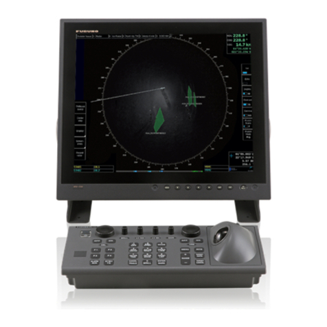
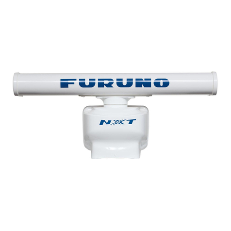
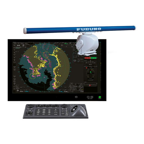
Furuno FAR-3220Z User manual

www.furuno.com
A
ll brand and product names are trademarks, registered trademarks or service marks of their respective holders.
Installation Manual
SURVEILLANCE RADAR
FAR-3220Z
IMPORTANT NOTICES.................................................................................................... i
SAFETY INSTRUCTIONS ............................................................................................... ii
SYSTEM CONFIGURATION .......................................................................................... iii
1. INSTALLATION.......................................................................................................1-1
1.1 Mounting Considerations ...................................................................................................1-1
1.2 How to Mount the Transceiver Unit....................................................................................1-1
2. WIRING....................................................................................................................2-1
2.1 Cabling Considerations......................................................................................................2-1
2.2 How to Fabricate Cables....................................................................................................2-2
2.3 How to Connect Cables .....................................................................................................2-3
2.4 Power ON/OFF ..................................................................................................................2-6
3. SETTINGS AND ADJUSTMENTS ..........................................................................3-1
3.1 How to Connect the Surveillance Radar for Settings and Adjustments .............................3-1
3.2 Settings from the PC(s)......................................................................................................3-2
3.3 Settings at Installation of the EC-3000...............................................................................3-2
3.4 How to Input Navigation Data ............................................................................................3-4
4. MAINTENANCE, SERVICE RELATED INFORMATION ........................................4-1
4.1 Parts Location ....................................................................................................................4-1
4.2 Jig, Tool .............................................................................................................................4-2
4.3 Wiring Caution ...................................................................................................................4-2
4.4 Cable Types.......................................................................................................................4-3
4.5 Periodic Replacement Parts ..............................................................................................4-3
4.6 Connection With the Transceiver Unit ...............................................................................4-3
SPECIFICATIONS ..................................................................................................... SP-1
OUTLINE DRAWING................................................................................................... D-1
INTERCONNECTION DIAGRAM ................................................................................ S-1

7KHSDSHUXVHGLQWKLVPDQXDO
LVHOHPHQWDOFKORULQHIUHH
࣭)85812$XWKRUL]HG'LVWULEXWRU'HDOHU
$VKLKDUDFKR
1LVKLQRPL\D-$3$1
$ 6(3
3ULQWHGLQ-DSDQ
$OOULJKWVUHVHUYHG
+ )(%
3XE1R ,0(+
5()8 )$5:
Z: FEB. 14, 2018
Pub. No. IME-36670-Z
FAR-3220Z

i
IMPORTANT NOTICES
General
• This manual has been authored with simplified grammar, to meet the needs of international users.
• The operator of this equipment must read and follow the descriptions in this manual.
Wrong operation or maintenance can cancel the warranty or cause injury.
• Do not copy any part of this manual without written permission from FURUNO.
• If this manual is lost or worn, contact your dealer about replacement.
• The contents of this manual and equipment specifications can change without notice.
• The example screens (or illustrations) shown in this manual can be different from the screens you
see on your display. The screens you see depend on your system configuration and equipment
settings.
• Save this manual for future reference.
• Any modification of the equipment (including software) by persons not authorized by FURUNO will
cancel the warranty.
• The following concern acts as our importer in Europe, as defined in DECISION No 768/2008/EC.
- Name: FURUNO EUROPE B.V.
- Address: Ridderhaven 19B, 2984 BT Ridderkerk, The Netherlands
• All brand and product names are trademarks, registered trademarks or service marks of their
respective holders.
How to discard this product
Discard this product according to local regulations for the disposal of industrial waste. For disposal in
the USA, see the homepage of the Electronics Industries Alliance (http://www.eiae.org/) for the
correct method of disposal.
How to discard a used battery
Some FURUNO products have a battery(ies). To see if your product has a battery, see the chap-
ter on Maintenance. Follow the instructions below if a battery is used. Tape the + and - terminals
of battery before disposal to prevent fire, heat generation caused by short circuit.
In the European Union
The crossed-out trash can symbol indicates that all types of batteries
must not be discarded in standard trash, or at a trash site. Take the
used batteries to a battery collection site according to your national
legislation and the Batteries Directive 2006/66/EU.
In the USA
The Mobius loop symbol (three chasing arrows) indicates that
Ni-Cd and lead-acid rechargeable batteries must be recycled.
Take the used batteries to a battery collection site according to
local laws.
In the other countries
There are no international standards for the battery recycle symbol. The number of symbols can
increase when the other countries make their own recycle symbols in the future.
Cd
Ni-Cd Pb
ii
SAFETY INSTRUCTIONS
Mandatory Action
Prohibitive Action
WARNING
Indicates a potentially hazardous situation which, if not avoided,
could result in death or serious injury.
CAUTION
Indicates a potentially hazardous situation which, if not avoided,
can result in minor or moderate injury.
Warning, Caution
DANGER
Indicates a potentially hazardous situation which, if not avoided,
will result in death or serious injury.
The installer of the equipment must read the applicable safety instructions before attempting to install
the equipment.
Do not open the equipment
unless totally familiar with
electrical circuits and
service manual.
Only qualified personnel are
allowed to work inside the
equipment.
WARNING
ELECTRICAL
SHOCK
HAZARD
Turn off the power at the mains
switchboard before beginning the
installation.
Fire, electrical shock or serious injury
can result if the power is left on or is
applied while the equipment is being
installed.
Be sure that the power supply is
compatible with the voltage rating
of the equipment.
Connection of an incorrect power
supply can cause fire or damage the
equipment.
Use only the specified power
cable.
Fire or damage to the equipment can
result if a different cable is used.
Note: For more information, please refer to IMO
SN/Circ.271 “Guidelines for the installa-
tion of shipborne radar equipment.”
WARNING
Do not install the transceiver unit
in a dusty environment, orone
where the unit may get wet from
rain or water splash.
Dust or water in the units can result in
fire, electrical shock, or damage to
the equipment.
Attach protective earth securely to
the ship's body.
The protective earth (grounding) is
required for the AC power supply to
prevent electrical shock.

iii
SYSTEM CONFIGURATION
• Basic configuration is shown with solid line.
• Equipment shown with dotted lines are local supply.
Category of units
Antenna unit: Exposed to the weather
Other units: Protected from the weather
Note: For de-icer connection, use
RU-3305 (100/230 VAC 1ø, 50-60 Hz).
PROCESSOR
UNIT
(EC-3000)
100-115 VAC
220-230 VAC
1ø, 50-60 Hz
Radar Control Unit (RCU-025)
ANTENNA UNIT
(XN20AF-RSB103 or
XN24AF-RSB103)
TRANSCEIVER UNIT
(RTR-116)
DISPLAY UNIT
(MU-231)
100-230 VAC
1ø, 50-60 Hz
Waveguide
200/380 VAC
3ø, 50 Hz
RU-5893
100 VAC 3ø, 60 Hz
RU-6522
220 VAC 3ø, 50 Hz
RU-5466-1
440 VAC 3ø, 50 Hz
100-115 VAC
220-230 VAC
1ø, 50-60 Hz
POWER SUPPLY
UNIT
(PSU-007)
LAN
To Surveillance Radar
processor

SYSTEM CONFIGURATION
iv
Program no.
xx: Minor change
The latest IHO standard can be found at http://www.iho.int
System Program no. Version no. Remarks
Antenna unit
SPU 0359407 01.xx
RF-Converter 0359414 01.xx
Processor unit (EC-3000)
Main 0359266 02.xx

1-1
1. INSTALLATION
1.1 Mounting Considerations
Keep in mind the following points when selecting a mounting location for the transceiv-
er unit.
• Locate the unit away from heat sources because of heat that can build up inside the
cabinet.
• Locate the unit away from places subject to water splash and rain.
• Leave sufficient space at the sides and rear of the unit to facilitate maintenance.
• Determine the location considering the length of the cable between the transceiver
unit and the antenna unit and the cable between the transceiver unit and the power
supply unit.
• Be sure to connect the ground wire (between the earth terminal on the chassis and
the ship’s earth).
1.2 How to Mount the Transceiver Unit
Fix the unit to the mounting location with M6 bolts or 6 coach screws. See the outline
drawing for mounting dimensions.
NOTICE
Do not apply paint, anti-corrosive sealant or contact
spray to coating or plastic parts of the equipment.
Those items contain organic solvents that can damage
coating and plastic parts, especially plastic connectors.

1. INSTALLATION
1-2
This page is intentionally left blank.

2-1
2. WIRING
2.1 Cabling Considerations
• To lessen the chance of picking up electrical interference, avoid where possible
routing the antenna cable (power and LAN) near other onboard electrical equipment
(radars, TX radio antennas, etc.). Also avoid running the cable in parallel with power
cables. When crossing with other cable, the angle must be 90° to minimize the mag-
netic field coupling.
• The antenna cable between the antenna and processor units is available in lengths
of 15 m and 30 m. Whatever length is used, it must be unbroken; namely, no splicing
allowed. The antenna cable should be as short as possible to minimize attenuation
of the signal.
• The radar must be connected to an emergency power source, as required by SO-
LAS II-1.
• The length of the USB cable must be within 5 m to prevent equipment trouble.
• The length of LAN cables must be within 50 m.
• Use a Cat5e or Cat6 LAN cable for the network if available locally.
• Make sure that the ground wires are connected between the ground terminals on
each equipment and the ship’s earth.
• Pass the cables through the specified clamp or locking wire saddle.

2. WIRING
2-2
2.2 How to Fabricate Cables
2.2.1 Antenna cable (TTYCYSLA-1)
2.2.2 Serial cable (TTYCYSLA-1Q)
2.2.3 LAN cable (FR-FTPC-CY)
Sheath
Sheath
Pass the heat shrink tubing
(local supply) onto the drain
wire. Attach a crimp-on lug
(FV1.25-4(LF) RED) to
the wire.
Vinyl
tape
Crimp-on lug
Clamp sheath with
cable clamp.
6
5
100
Drain wire
450
Sheath
Sheath
Sheath
Sheath
(1)
(2)
5
50
SheathSheath
Pass the heat shrink tubing
(local supply) onto the drain
wire, then attach a crimp-on
lug (FV1.25-4(LF) RED) to
the wire.
Crimp-on lug
6
5
100
Drain wire
450
5
SheathSheath
Vinyl
tape
Clamp sheath with
cable clamp.
SheathSheath
50
Armor
Heat shrink
tubing
Heat shrink
tubing
Flame retardent
vinyl sheath
Flame retardent
vinyl sheath
Flame retardent
vinyl sheath
(Set this part in
the cable clamp.)
Flame retardent
vinyl sheath
(Set this part in
the cable clamp.)
Vinyl sheathVinyl sheath
LAN connector w/shield
(equivalent to J00026A0165)
LAN connector w/shield
(equivalent to J00026A0165)
40 mm ±10 mm 700 mm
+20 mm, -0 mm

2. WIRING
2-3
2.2.4 Flexible waveguide
The connector at the antenna side is preattached to the flexible waveguide. The bend-
ing radius shown below must be observed to prevent damage to the waveguide.
E-bend: 200 mm, H-bend: 400 mm
2.3 How to Connect Cables
2.3.1 How to connect the antenna cable, serial cable, and LAN cable
1. Remove the cover of the unit.
2. Lay the cables in respective cable slots so their armors rest in the slots.
3. Connect the power line of the serial cable to the RF-TB Board as shown in the fig-
ure below.
LAN cableSerial cable
Clamp
Antenna cable
Insertion
point
● Antenna cable: TB803
● Serial cable: TB803
TB803 TB801
Antenna cableSerial cable
Wire
How to connect wires to WAGO connector
Press downward.
Terminal
opener
WAGO
connector
Twist
<Procedure>
1. Twist the cores.
2. Press the terminal opener downward.
3. Insert the wire to hole.
4. Remove the terminal opener.
5. Pull the wire to confirm that it is secure.

2. WIRING
2-4
Pin arrangement ofTB803 on RF-TB Board (03P9570)
4. Make the following connections inside the transceiver unit.
• Pass the LAN cable through the locking wire saddles circled in the figure below,
then connect the cable to J712.
• Pass the serial and antenna cables through the locking wire saddles circled in
the figure below. Connect the drain wires of the cables to the location specified
in the figure below.
5. Check that cables are lying in their cable slots then fasten the cable clamp.
Pin No. Signal In/Out Remarks
1 ANT_ON Out 12V, connect to PSU-007.
2GND
3N.C.
4N.C.
5N.C.
6 P12V Out Power for Heading and Bearing
7N.C.
8 HD_B In Heading, 5V
9 BP_A In Bearing, 12V, 360ppr
10 N.C.
11 GND
12 N.C.
13 N.C.
14 N.C.
15 GND
16 TRIG Out N.C., for testing
Connect the LAN cable to J712.
Pass the LAN
cable through
these locking
wire saddles.
Pass the serial
and antenna
cables through
these locking
wire saddles.
Connect the drain
wire of the anten-
na cable and
serial cable here.

2. WIRING
2-5
2.3.2 How to connect the power cable
1. Remove the connector cover for the power cable.
2. Fabricate the power cable (TPY-1.5) as shown below.
3. Pull up the plastic cover and connect the power cable.
4. Remount the cover.
5. Reattach the cover of the power supply unit.
2.3.3 How to connect the flexible waveguide (FR-9)
The RF interconnection between the antenna unit and the transceiver can be made
with a flexible waveguide (FR-9). If the rectangular waveguide is used, observe the fol-
lowing installation guidelines.
• Correctly installed waveguide runs ensure the most efficient transmission of electri-
cal energy at high frequencies. Electrical losses, however, occur in the waveguide
runs. To minimize them the following factors are of great importance: minimum
length, airtightness and electrical continuity.
• Another consideration required is that of frequency disturbance. The transmitting
valve, a magnetron, is the primary oscillator in the radar. This is different from the
oscillation system at lower frequencies in which conventional radio valves are used.
In the latter case, the primary oscillator is always protected from the effects of load
impedance by a buffer stage so that frequency and waveform are left unobstructed.
With a waveguide and magnetron, however, mismatch of impedance causes “fre-
quency pulling.” For this reason, the number of possible mismatches in a waveguide
run, i.e., joins and bends, must be kept minimum.
• Each pair of flanges should be coupled with one O-ring, four bolts and spring wash-
ers and the choke flange must be in the upper position. The bolts and O-ring must
be greased before insertion to facilitate removal if required at a later date.
FG
Connector cover
Sheath (clamp here.)
Crimp-on lug
(FV2-M4)

2. WIRING
2-6
• The transceiver unit output flange is a plain type and the antenna unit output flange
is a choke type, and it is important to maintain this relationship throughout the wave-
guide run.
• After installation of the waveguide is completed, the coupling portions must be
sealed by using the adhesive supplied.
• In a very short time the surface of the waveguide becomes green with verdigris.
Therefore, paint both the surface of the waveguide and flanges to avoid corrosion
and water penetration. Paint must not be allowed to reach the inner surface of the
waveguide or the mating surface of any flange.
2.4 Power ON/OFF
Use the MAIN SW on the transceiver unit to power the unit on or off. The start-up time
is approx. one minute. (The fan starts rotating when the start-up is completed.) This
unit is not linked with the power ON/OFF of the EC-3000.
Thru-deck hole Weld here.
Deck
TRANSCEIVER
UNIT
Drain waveguide
Watertight film

3-1
3. SETTINGS AND ADJUSTMENTS
3.1 How to Connect the Surveillance Radar for
Settings and Adjustments
Among the equipment setting menus, those that set values specific to the surveillance
radar cannot be displayed in the menu of EC-3000. These items are set by connecting
laptop PC(s) to the LAN.
3.1.1 How to connect PC(s) to the surveillance radar
As shown in the figure below, there are two ways to connect PC(s) to the surveillance
radar.
Method 1: Connect a pair of laptop PCs to the EC-3000 with two HUBS, as shown by
(1) and (2) in the figure below.
Method 2: Connect a monitoring PC directly to the EC-3000, as shown by (3) in the
figure below.
3.1.2 Software connection
Use TeraTerm* to connect to the SPU board by using TCP/IP. For the network con-
nection, see the applicable document, issued separately.
Be sure the IP address of the SPU board is not the same as the one for the monitoring
PC.
* An open-source software package designed to be used for emulation purposes.
Antenna
Unit
Waveguide
Transceiver
Unit
EC-3000
LAN
HUB
Laptop
PC
Laptop
PC
HUB Monitoring
PC
Main observation room
Remote radar
installation room

3. SETTINGS AND ADJUSTMENTS
3-2
3.2 Settings from the PC(s)
Enter the following commands in a text file and use TeraTerm to send the file to the
EC-3000.
3.2.1 Antenna height
Antenna height cannot be set from the EC-3000. Set it with a command as follows.
3.2.2 TX channel (TX_CH)
3.3 Settings at Installation of the EC-3000
3.3.1 Initial pulse length settings for each range
Menu operation: MENU[1 ECHO][1 CUSTOMIZE ECHO][8 PULSE]
Set the pulse length for the ranges shown in the table below.
Menu operation for restoring default pulse lengths: MENU[1 ECHO][1 CUS-
TOMIZE ECHO][0 DEFAULT]
After restoring the pulse lengths, select [SAVE] to save the settings.
Antenna
height (m) Command Antenna
height (m) Command
5 changeanth 0 0 60 changeanth 0 11
7.5 changeanth 0 1 70 changeanth 0 12
10 changeanth 0 2 80 changeanth 0 13
15 changeanth 0 3 90 changeanth 0 14
20 changeanth 0 4 100 changeanth 0 15
25 changeanth 0 5 110 changeanth 0 16
30 changeanth 0 6 120 changeanth 0 17
35 changeanth 0 7 130 changeanth 0 18
40 changeanth 0 8 140 changeanth 0 19
45 changeanth 0 9 150 changeanth 0 20
50 changeanth 0 10
TX CH Command
CH1 txchset 1
CH2 txchset 2
CH3 txchset 3
Range (nm) Pulse length setting
0.5 S1
0.75 S1
1.5 S1
3S2
6M1
12 M1
24 M2

3. SETTINGS AND ADJUSTMENTS
3-3
3.3.2 Second-trace echo rejection
Menu operation: MENU[1 ECHO][5 2ND ECHO REJ][OFF]
3.3.3 Interference rejector
Click the [IR] button on the InstantAccess
bar™, then click desired rejection level (or
OFF). The higher the number the greater
the degree of interference rejection. It is
recommended to use [IR1] when using the
“long” pulse length.
3.3.4 Beam width
In order to determine the minimum echo detection width of the TT echo, set the anten-
na nominal beam width.
3.3.5 IR setting for TT FrontEnd
Menu operation MENU[9 RADAR INSTALLATION][4 TT PRESET][NEXT]
[3 TT DETAIL DATA]No. 88
Setting Beam width [deg] 100
Example: beam width 0.75 deg=0075
Remarks The beam width setting range is 0.01 to 6.00. If you select the an-
tenna type with [8 INITIAL SETTING][5 ANT SELECT], the preset
of No. 88 will be changed.
Note: TT tracking performance may be affected when the antenna
length is long and the horizontal beam width is small, because the
number of times the transmitted radio wave strikes the target de-
creases.
Menu operation MENU[9 RADAR INSTALLATION][4 TT PRESET][NEXT]
[3 TT DETAIL DATA]No. 94
Setting 3 m antenna, 24 rpm=1025
For other antenna length, antenna rotation speed, see below for the
setting method.
Ones place digit: Set between 0 and 5 according to beam width
and antenna rpm. In each pulse setting, compare the echo display
with the QV display. If the target displayed in the echo display is not
shown in QV, turn off the IR of the TT front end above that pulse set-
ting.
Tens place digit: Fixed at “2”.
Hundreds, Thousands place digit: Antenna rotation speed ap-
prox. 0.4. (Since the antenna rotation changes slightly by wind etc.,
it is recommend to use a value close to the nominal value of the ro-
tation speed.)
See “Detailed meaning of setting value” below.
Remarks The default setting is “6006” (IR ON). This setting may not display
the QV echo when the pulse length is “LONG”. The QV is turned on
or off by MENU[9 RADAR INSTALLATION][4 TT][3 QV DIS-
PLAY]ON / OFF
[IR]
button
[IR] button

3. SETTINGS AND ADJUSTMENTS
3-4
Detailed meaning of setting value
Each of the ones place digit, tens place digit, hundreds place digit and thousands
place digit have meanings.
(1) The ones place digit indicates the boundary of the pulse length that turns off the
IR of the TT front end.
For example, to set “pulse length M2 - L, IR OFF”, set the ones digit to “3”. (The
default setting for the ones digit is “6”, which turns off IR no matter the pulse length.)
(2) The tens place has the meaning shown in the table below.
(3) The hundreds and thousands places indicate the boundary value of the antenna
rotation speed (rpm) that turns off IR.
The table shows preset values and their content.
3.4 How to Input Navigation Data
Because navigation data is not automatically input to the EC-3000, it is necessary to
enter the mode as type=B, and enter heading, speed and position manually.
The operator can select navigation sensors to use for navigation and view their current
values on the applicable page in the [System Sensor Setting] and [Local Sensor Set-
ting] menus. To access these menus, right-click the Sensor information datum box,
then click [Select Sensor] followed by [Setting].
The descriptions in this section show the sensor menus in the radar mode. The sensor
menus in the chart mode mirror those in the radar mode, although the layout is differ-
ent. Any change made in a sensor menu is reflected to the companion sensor menu,
to synchronize the data between the modes.
Pulse length Setting
S1 0
S2 1
M1 2
M2 3
M3 4
L5
Setting Content
0IRalwaysON.
1ACE ON: IR is turned OFF according to pulse length and
antenna rpm.
2ACE OFF: IR is turned OFF according to pulse length and
antenna rpm.
3IRalwaysOFF.
Setting Content
3614 Antenna rotation 36 rpm, ACE ON, IR is turned off when
pulse length is M3 - L.
3604 Tens place is “0”, which means IR is always ON. IR is al-
ways ON regardless of value of ones place, one hundreds
place and or thousands place.
3634 Tens place is “3”, which means IR is always OFF. IR is al-
ways OFF regardless of value of ones place, one hun-
dreds place or one thousands place.

3. SETTINGS AND ADJUSTMENTS
3-5
3.4.1 Sensors menu
[HDG] page (Local Sensor)
[Sensors]: Select the heading sensor to use.
[Analog Gyro]: No use.
[Manual]: Set heading manually when there is no head-
ing sensor available.
[Gyro Correction]: Set correction manually for the head-
ing value. (Not available with the [System Sensor Set-
ting] menu.)
[SPD] page (System Sensor)
[Stabilization Mode]: Select the water stabilization
mode: Select [Bottom] for ground stabilization, or select
[Water] for sea stabilization.
[Sensor Type]: Select [GPS] in case of a GPS naviga-
tor, or [LOG] for speed log.
[Data Source]: Check [Sensors] to use a sensor in the
[Sensors] list, or click [Manual] to enter speed manually.
Use [Manual] when no speed source is available.
[Manual]: Input speed manually. Check [Water] in [Sta-
bilization Mode] and deactivate the AIS function to en-
able entry.
[Reference SPD]: Check to use radar as the source for
speed and course. (Only available with the Local Sen-
sor Setting and checking [Bottom] in [Stabilization
Mode].)
[Set Drift]: Check the [Set Drift] checkbox to manually
set speed and course of drift. Note that you can select
manual drift only if you check [Water] in [Stabilization
Mode].
Angle = Difference between heading and COG
Spd = Speed component of the drift vector
Cse = Course component of the drift vector
Vector defined by (SOG and COG) is equal to vector sum of vectors defined by (SPD
and HDG) and (set and drift).

3. SETTINGS AND ADJUSTMENTS
3-6
[POSN] (Position) page
The sensor label (here, GPS001, GPS002) indicates
the name of the sensor.
[Data Source]: Check [Sensors] to use a sensor in the
[Sensors] list, or click [DR] to enter position manually.
When the position source is changed based on priori-
ties and signal validity to another position source, then
you get the Alert 472 (ALF format: 10602,1) "Position
Source Change".
[DR]: Check [DR] when no position source is available.
HDG
spd
SOG
COG
cse
SPD: water speed
HDG heading of ship
SOG: speed over ground
COG: course over ground
spd: speed of drift
cse: course of drift
angle: difference between HDG and COG
North
SPD
angle
Table of contents
Other Furuno Radar manuals

Furuno
Furuno DRS4A User manual

Furuno
Furuno WR2120 User manual

Furuno
Furuno FAR2137S/12 User manual

Furuno
Furuno FAR-3320SW User manual

Furuno
Furuno FAR-3210 User manual

Furuno
Furuno FCR-1030 User manual

Furuno
Furuno DRS12AX X-Class User manual

Furuno
Furuno FAR-3210 Manual

Furuno
Furuno FRS1000 Operator's manual

Furuno
Furuno FR-1500 MARK-3 User manual

Furuno
Furuno WR-2100 User manual

Furuno
Furuno WR2120 User manual

Furuno
Furuno FR-1908V-BB User manual

Furuno
Furuno WR-2100 User manual

Furuno
Furuno WR110 User manual

Furuno
Furuno DRS6A User manual

Furuno
Furuno FAR-3210 User manual

Furuno
Furuno FR-2105 User manual

Furuno
Furuno DRS4D-NXT User manual

Furuno
Furuno FR-1500 User manual