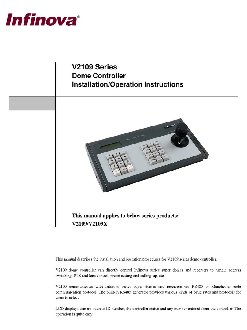
Infinova V2923ACN Series Installation instructions

V2923ACN Series
External CPU Module
Installation/Operation Instructions
This manual applies to below series products:
V2923ACN
This manual describes the operation and programming procedures for the V2923ACN External CPU Module.
Utilizing the latest advancement of ARM9 microprocessor and based on the LINUX operation system, V2923ACN
External CPU Module can provide automated electronic surveillance or it can allow even a single user to control an
entire CCTV system of up to 1024 video inputs by 128 video outputs.
The software-embedded Central Processing Unit (CPU) is the "heart" of the switching system. It controls the system
switching bays, provides PTZ controls for site cameras, and offers the programming menus for system setup.


Notice
Copyright Statement
This manual may not be reproduced in any form or by any means to create any derivative such as translation, transformation, or adaptation
without the prior written permission of Infinova.
Infinova reserves the right to change this manual and the specifications without prior notice. The most recent product specifications and
user documentation for all Infinova products are available on our website www.infinova.com.
Trademarks
Infinova
®
is a trademark of Infinova.
Copyright © 1993-2014 Infinova. All rights reserved.
All other trademarks that may appear belong to their respective proprietors.
FCC Warning
V2923ACN External CPU Module complies with Part 15 of the FCC rules.
Operation is subject to the following two conditions.
This device may not cause harmful interference.
This device must accept any interference received, including interference that may cause undesired operation.
V2923ACN External CPU Module has been tested and found to comply with the limits for Class A digital device, pursuant to Part 15 of the
FCC rules. These limits are designed to provide reasonable protection against harmful interference when the equipment is operated in a
residential environment. This equipment generates, uses, and can radiate radio frequency energy and, if not installed and used in
accordance with the instructions, may cause harmful interference to radio communications. However, there is no guarantee that interference
will not occur in a particular installation.

Read this manual carefully before installation. This manual should be saved for future use.
Important Safety Instructions and Warnings
Electronic devices must be kept away from water, fire or high magnetic radiation.
Clean with a dry cloth.
Provide adequate ventilation.
Unplug the power supply when the device is not to be used for an extended period of time.
Only use components and parts recommended by manufacturer.
Position power source and related wires to assure they will be kept away from ground and access way.
Refer all service matters to qualified personnel.
Save product packaging to ensure availability of proper shipping containers for future transportation.
Indicates that the un-insulated components within the product may carry a voltage harmful to humans.
Indicates operations that should be conducted in strict compliance with instructions and guidelines contained in this manual.
Warning: To avoid risk of fire and electric shock, keep the indoor product away from rain and
moisture!

Table of Contents
Chapter I General Description ..................................................... 1
1.1 Description............................................................................ 1
1.2 Features................................................................................. 1
1.3 Important Terminology ......................................................... 1
Chapter II System Connection ..................................................... 4
2.1 Panel Description.................................................................. 4
2.2 Hardware Connection ........................................................... 4
2.2.1 Communication Port Connections................................. 4
2.2.2 Ethernet Connections .................................................... 5
2.2.3 Power Supply Connections............................................ 5
Chapter III System Operation...................................................... 6
3.1 Keyboards ............................................................................. 6
3.2 Keyboard Password Entry..................................................... 7
3.3 Video Selection ..................................................................... 7
3.4 Camera Control..................................................................... 8
3.5 Running a Tour ..................................................................... 8
3.6 Calling a Preset ..................................................................... 8
3.7 Calling a System Salvo ......................................................... 8
3.8 Activating an Auxiliary ......................................................... 9
3.9 Acknowledge an Alarm......................................................... 9
3.10 Non-host CPU Menu Programming Download .................. 9
3.11 Time Calibration ................................................................. 9
3.12 Keyboard and User Grouping ............................................. 9
3.13 Camera Grouping.............................................................. 10
3.14 Monitor Function .............................................................. 10
3.15 Pseudo Camera and Mapping Pseudo Setup ..................... 10
3.16 System Backup ................................................................. 10
3.17 Menu Language Selection................................................. 10
Chapter IV System Setup............................................................ 11
4.1 System Reset....................................................................... 11
4.2 Monitor Display Arrangement ............................................ 11
4.3 Monitor Tour Programming ................................................ 11
4.4 Setting Date Format/Setting Day of the Week .................... 12
4.5 Setting Preset ...................................................................... 12
4.6 Camera Lockout.................................................................. 12
4.7 Arming Monitors................................................................. 12
4.7.1 Alarm Display Modes ................................................. 13
4.7.2 Alarm Clearance Methods........................................... 13
4.7.3 Monitor Arming Types................................................ 14
4.7.4 Arming/Disarming a Monitor...................................... 14
Chapter V Menu Programming ................................................. 15
5.1 Main Selection Menu .......................................................... 15
5.2 Menu Navigation and Operation......................................... 15
5.3 System Menu ...................................................................... 15
5.3.1 Setting Time and Date ................................................. 15
5.3.2 Setting System Tours .................................................. 17
5.3.3 Set System Salvos ....................................................... 18
5.3.4 Set Event Timer........................................................... 20
5.3.5 Set Alarm .................................................................... 21
5.3.5.1 Set Monitor Arm Types............................................ 21
5.3.5.2 Set Alarm Contacts................................................... 21
5.3.5.3 Set Monitor Contacts................................................ 24
5.3.5.4 Set Alarm Title......................................................... 24
5.3.6 Set Source Groups....................................................... 25
5.3.6.1 Set Keyboard Groups ............................................... 25
5.3.6.2 Set User Groups ....................................................... 25
5.3.6.3 Set Camera Groups................................................... 25
5.3.7 Set Priority and Users.................................................. 26
5.3.7.1 Set Login Mode........................................................ 26
5.3.7.2 Set Priority ............................................................... 26
5.3.7.3 Set User.................................................................... 27
5.4 Monitor Menu..................................................................... 28
5.4.1 Set Monitor Attribute .................................................. 28
5.4.2 Set Monitor Function .................................................. 29
5.4.3 Monitor Status............................................................. 30
5.5 Camera Menu...................................................................... 30
5.5.1 Assign Pseudo Cameras .............................................. 31
5.5.2 Camera Title................................................................ 32
5.5.3 Camera/Keyboard/User Priority Setup........................ 32
5.5.4 Batch Pseudo Setup..................................................... 33
5.5.5 Clear Setting................................................................ 33
5.5.6 Video Loss .................................................................. 34
5.6 Port Menu ........................................................................... 34
5.7 Non-host matrix Configuration........................................... 35
5.7.1 Host Matrix Network Setup ........................................ 36
5.7.1.1 Local Site Number ................................................... 36
5.7.1.2 Video Trunk Assignments........................................ 37
5.7.1.3 Remote Site IP Address............................................ 38
5.7.2 Non-host Matrix Network Setup ................................. 38
5.7.3 Non-host Matrix Switcher Download Setup................ 39
5.8 System Backup ................................................................... 39
5.9 Language Selection............................................................. 40
Appendix I System Alarm Programming.................................. 41
Appendix II System Channel Programming ............................. 42
Appendix III ASCII / HEX System Control Codes .................. 42
Appendix IV Specifications ........................................................ 43
Appendix V Typical System Application................................... 44
Appendix VI Cable Diameter Calculation and Lightning &
Surge Protection................................................................... 45


1
Chapter I General Description
1.1 Description
The software-embedded Central Processing Unit (CPU) Module is
the "heart" of the switching system. It controls the switching bays
of V2040A series matrix switching systems, provides PTZ controls
for site cameras, and offers the programming menu for system
setup.
The V2923ACN External CPU utilizes ARM9 microprocessor
technology, based on LINUX operation system, providing powerful
performance. The ARM9 microprocessor is a 32-bit embedded
system processor, featuring low power consumption and high
performance.
Network Video Capability
Multiple V2923ACNs can be networked to provide both local and
remote control of the site cameras via the UDP protocol. Each
V2923ACN unit in the network is referred to as a node, and each
node in the network maintains all of its full features. To identify
V2923ACN in a network, each unit is allocated a unique site
number, which is assigned through the programming menu.
Easy Operation & Powerful Programming
Utilizing ARM9 microprocessor and LINUX operation system core,
V2923ACN can provide automated electronic surveillance,
allowing even a single user to control an entire CCTV system. A
maximum of 1024 video inputs and 128 video outputs can be
controlled from any one of up to 40 local keyboards and 254
network keyboards, PCs and other devices.
V2923ACN provides powerful menu-driven programming,
featuring 128 user-defined system tours, 128 salvos, 35 event timers,
5 alarm display methods and 3 alarm clearance methods. Optional
character information (e.g., date, time, video input number, video
output title and monitor status) can also be programmed to aid site
surveillance and system operation.
Available Windows-based system setup software greatly simplifies
the initial setup procedure as well as ongoing maintenance of
system parameters. The CPU communicates with controllers or PCs
via either RS-232 data or UDP protocols. Optional GUI software
V2210 further simplifies system operation and programming by
integrating all functions in an easy-to-use Windows application.
Third-party applications written in ASCII codes can also be adopted
for the system.
System Security
System security involves two approaches: System Partitioning and
User Priority. System Partitioning provides keyboard partition and
camera partition to implement detailed control between monitor,
camera and keyboard.
With User Priority, system administrators can define a maximum of
64 system users, and assign each user a password and a priority
level. Each of the 99 priority levels can also be configured as
desired, permitting different access controls for different
users/keyboards.
Network Retransmission
V2923ACN is capable with powerful network retransmission,
which can retransmit various information (such as video lost,
keyboard control, network checking status, the temperature, voltage
and power current information of network checking CPU and
arming/disarming information) to PC directly.
Continuous Performance
V2923ACN is designed for continuous duty operation. Therefore,
there will be no need for any inner maintenance once the
installation is finished. System programming, both via keyboard or
GUI software, is noninvasive and does not require rebooting or
power cycling for storage and/or execution of programmed settings.
All the communication ports adopt standard low-voltage interfaces
such as RS-232, High Speed Data Line and N.C/N.O switching
signal, and all connections/disconnections do not require rebooting
or power cycling. It is also the same with video connections.
1.2 Features
Up to 1,024 video inputs by 128 video outputs.
ARM9 microprocessor and LINUX operation system core for
powerful performance.
Ethernet network controllable, external CPU for added
networking features
Windows-based multimedia management software.
Built-in system diagnostics and dedicated system status report.
Control of fixed or variable speed pan/tilt and dome cameras on
Manchester, RS-422, or RS-485 PTZ protocols.
Available internal video loss detection.
10 flexible RS-232 ports (expandable to 40).
Display information on screen.
Independent monitor tour.
128 tours, 35 event timers and 128 salvos.
Automatic alarm call-up, up to 1024 alarm inputs.
5 alarm display methods and 3 alarm clearance methods.
Detailed priority control between monitor/camera/keyboard via
keyboard grouping and camera grouping configuration.
User priority and password management
Up to 255 V2923ACN nodes can be inter-connected in one
network video system.
1.3 Important Terminology
1. System Keyboard
System Keyboards are the Infinova keyboards for system
control and programming, including V2117, V2116, V2115
full system keyboard, and V2110 operator control keyboard.
V2923ACN can be controlled by up to 40 local keyboards and
254 network keyboards. Different keyboards can be used for
operation simultaneously. Please refer to relevant keyboard
manuals for further instructions.

2
2. Preset, Salvo, System Tour and Event Timer
Preset enables the system to pre-define and save camera
scenes, which can be called up for display either
automatically by the system upon alarms or by operators via
keyboards. Descriptions for the relevant scenes can also be
displayed on monitors at the same time. The Infinova series
receivers and Super Dome cameras are capable of defining
up to 255 such camera scenes.
Salvo permits users to switch a group of cameras to a group
of monitors, hereby providing convenient surveillance over
different scenes simultaneously.
System Tour enables operators to display different camera
scenes, presets and salvos continuously on the same monitor.
One camera scene or one preset can be included in the same
Tour multiple times.
Event Timer permits the system to automatically call up
system tours at a pre-programmed time.
3. Monitor Tour
A monitor Tour is a temporary sequence of cameras for a
called monitor. The sequence can only be displayed on the
called monitor.
4. Control Interface
V2923ACN system provides its controllers and auxiliaries
with following interfaces:
Multiple V2923ACN sites establish inter-communication via
UDP in a network video system;
Controller stations (such as keyboards, PCs) establish
communication with V2923ACN via RS-232 interfaces;
The V2431 Alarm Interface Units communicate with
V2923ACN via RS-232 interfaces to Control alarms;
The Monitor specifically for menu programming (PROG
MON) Communicates with V2923ACN via PROG MON port;
The V2411 Code Generator/Distributors, looping through
DATA LINE with V2923ACN, are used to provide Manchester
Control code for site cameras;
Infinova series Followers (including V2421A, V2422A, and
V2423A) switch external circuits when designated cameras are
called up to designated monitors (V2421A), when designated
monitors are in alarm conditions (V2422A), or when
designated auxiliaries are called up (V2423A). They all
communicate with V2923ACN via high-speed DATA LINE.
5. System Priority
System priority provides operators with the following detailed
controls:
Keyboard-to-Monitor: Set the keyboard group that can
control the monitor;
Keyboard-to-Camera View: Set the keyboard group that can
view the camera;
Keyboard-to-Camera Control: Set the keyboard group that
can control the camera;
Monitor-to-Camera: Set the camera group that can be
displayed on the monitor.
6. Alarm Handling
V2923ACN system, when communicating with the V2431
Alarm Interface Units, provides up to 1024 alarm inputs, and
features powerful alarm handlings such as:
Calling up any system video input upon alarm;
Calling up pre-defined scenes upon alarm;
Triggering auxiliary relay switches for site cameras upon
alarm.
7. Auxiliary Outputs
Local auxiliary outputs are provided via the V2431 Alarm
Interface Units (AIUs) to activate VCRs or other alarm
devices.
8. Pseudo Numbers, Real Numbers and Reflection Numbers
V2923ACN system assigns Pseudo Numbers for up to 1024
local cameras or cameras of the remote site for ease of system
management. A Pseudo Number is the logical number the
system assigns to a specific camera. The camera's Real
Number, the actual physical camera number, can also be used
in the system. Reflection Number indicates camera address in
the system. It is another Real Number which is added behind
the Pseudo Number, so the operations to the current camera
(Real Number) will be mapped to the other camera (Reflection
Number).
9. Network Node
Each V2923ACN in the network is referred to as a node. Each
node in the network maintains all of its full features. To
identify V2923ACNs in a network, each unit is allocated a
unique site number through the programming menu. Of which,
sites from 241 to 250 are defaulted as network keyboards.
10. Power Supply and its installation
System Power Supply herein refers to the standard power
supply for V2923ACN. V2923ACN can be powered with
100VAC~240VAC standard power supply.
NOTE: When powering V2923ACN, check that the power supply
specifications correspond to those required. The use of improper
appliances may seriously compromise the safety of the personnel
and the installation.

3
Table 1-1 System Accessories
V2115 series
System Keyboard
Full system programming and control
Communicates with matrix switching systems via RS-232
Fixed and variable speed joystick
V2116 series
System Keyboard
Full system programming and control
Communicates with matrix switching systems via RS-232 or with Ethernet network via
UDP
LCD displays of camera and monitor
Direct control via Manchester or RS-485 outputs
Fixed and variable speed joystick
V2117 series
System Keyboard
Full system programming and control
Communicates with matrix switching systems via RS-232 or with Ethernet network via
UDP
LCD displays of camera and monitor
Direct control via Manchester or RS-485 outputs
Fixed and variable speed joystick
Communicates with DVR via RS-485 port or Ethernet port
V2110
Operator Keyboard
4 digital LED displays of camera and monitor
Fixed and variable speed joystick
Monitor tour programming and control
Alarm Acknowledge clear
Communicates with all Infinova matrix switching systems via RS-232
V2405A-4 Port Expander Expands each RS-232 port on the system's CPU into four RS-232 ports
V2210
User Interface Software
Windows based
Graphical User Interface
Complete system control using on-screen keyboard
Live video windows (optional video card)
E-maps, control menus and icons, password encryption and login
Convenient arming/disarming
V29X3SW
System Setup Software
Windows based
Uploads and downloads the system setup data
V1691 Series
Receiver/Drivers
Manchester or RS-485 (INFINOVA, SAMSUNG, PELCO-P/D) control code input
24VAC or 14VDC output optional
Multiple presets and autopan functions
Local diagnostic mode
Pan/tilt and camera control
V2411MA/V2411-485/
V2411-422 series
Code Converter
Data line signal input to 64 Manchester code outputs
Data line signal input to 16 RS-485 code outputs
Data line signal input to 8 RS-422 code outputs
V2431
Alarm Interface Unit
64 alarm inputs (normally open or normally closed contacts)
Multiple units can be cascaded on 1 RS-232 data stream
V2421A
Switch Follower
Provides 2 groups of 16 (32) Double Pole Form-A relays
Relays follow switching of camera to monitor
Manually or automatically activates accessories such as Intercoms and lights
Multiple units can be cascaded for system expansion
V2422A
Alarm Follower
Provides 2 groups of 16 (32) Double Pole Form-A relays
Relays follow the alarmed monitors
Multiple units can cascaded for system expansion
V2423A
Auxiliary Follower
Provides 2 groups of 16 (32) Double Pole Form-A relays
Relays respond to activation of linked camera auxiliary command
Manually or automatically activates auxiliary accessories
Multiple units can be cascaded for system expansion

4
Chapter II System Connection
2.1 Panel Description
Front Panel
On the front panel, a LED power indicator and a LCD display is
provided, as shown in Figure 2-1.
POWER
SYSTEM CPU
1 2
Infinova
R
Figure 2-1. V2923ACN External CPU Front Panel
1. System Info. Display - This LCD panel indicates the current
system information, such as date and time, video loss
information.
2. . Power – This LED indicates the system power status.
Rear Panel
On the rear panel, ten RS-232 ports, one Ethernet port, two high
speed data line outputs and one programming monitor output are
provided, as shown in Figure 2-2.
DATA LINE RS232 PORTS ETHERNET PROG MON
1 2 1 2 34 56 7 8 9 1011
45621 3
Figure 2-2. V2923ACN External CPU Rear Panel
1. Data Line 1 – Routes V2923ACN CPU control signal to pan/tilt,
lens, and auxiliary functions at suitably equipped sites, up to
1024. Data Line 1 also routes the matrix switching information
for video outputs 1- 64.
2. Data Line 2 – Routes V2923ACN matrix switching information
for video outputs 65-128.
3. RS-232 PORTS - These ten RS-232 ports provide interfaces for
communication with keyboards, PCs, and other devices such as
the V2431 Alarm Interface Unit. Each port is programmable for
baud rate, data bits, stop bits, parity and type of use.
4. Ethernet Port - This Ethernet port is used to connect V2923ACN
to a Hub or switch via UDP to form a network video system.
5. PROG MON - The output for the system programming monitor
(PROG MON) that displays programming menus.
6. Power Switch and power inlet.
2.2 Hardware Connection
All internal switch settings on the modules should be made before
system connections are started. Ensure that all connections are
properly completed before applying power.
To facilitate maintenance and assist in service, all connecting cables
should be identified with source/destination numbers.
2.2.1 Communication Port Connections
The External CPU of V2923ACN each provides ten RS-232
communication ports for connection with auxiliary equipment, e.g.,
keyboards, controllers, computers and alarm interface units.
The ten RJ-45 communication ports are respectively labeled as
PORT 1 through 10, and are expandable up to 40 ports with
V2405A-4 series port expanders.
8 7 6 5 4 3 2 1
The Pins Definition:
5: Data Receiving
4: Data Transmitting
2/7: Grounding
Note: All the RS-232 ports are configured with the following
default settings: baud rate - 1200, parity bit - none, date bits - 8,
stop bits - 1.
Standard Terminal Boxes (Figure 2-3) are provided for
communication port connections. Their pin definitions are detailed
in the following table.
Table 2 -1
Pin No. Signal Definition
1 Unused
2 Ground
3 Unused
4 Data receiving
5 Data sending
6 Unused
7 Ground
8 Unused
Keyboard with no direct power input, such as V2110,
requires a terminal box for connection, as shown below:
Figure 2-3. Terminal Box
V2923ACN’s wiring instructions are detailed in the following
diagrams:
Standard DTE (PC) V2923ACN RJ-45
DB9Connector 8-pinconnector
3 ----------------------------- 5
2 ----------------------------- 4
5 ----------------------------- 7
Figure 2-4. Connect V2923ACN to a computer RS-232 port
V2116 Keyboard RJ-45 V2923ACN RJ-45
8-pin Connector…………………………8-pin connector
5 ----------------------------- 4
4 ----------------------------- 5
2 ----------------------------- 7
Figure 2-5. Connect V2923ACN to V2116

5
V2110 Keyboard RJ-45 Terminal Box V2923ACN RJ-45
8-pin Connector From Keyboard to V2923ACN 8-pin connector
4 ---------------------5-----------------4--------------------- 5
5 ---------------------4-----------------5--------------------- 4
7 ---------------------2-----------------2--------------------- 7
1 ----------------------------------------8--------------------6VAC
8 ----------------------------------------1--------------------6VAC
Figure 2-6. Connect V2923ACN to V2110 through a terminal box
Note: Please use the supplied modular cables to make the system
connections.
POWE
R
ALARM
C
O
M
INPU
TOUTPUT
ABCDEFG
H
123456
AAAAAA
25 26 27 28 29 30
AAAAAA
31 32 33 34 35 36
AAAAAA
789101112
AAAAAA
49 50 51 52 53 54
AAAAAA
55 56 57 58 59 60
AAAAAA
37 38 39 40 41 42
AAAAAA
13 14 15 16 17 18
AAAAAA
61 62 63 64
AAAA
43 44 45 46 47 48
AAAAAA
19 20 21 22 23 24
AAAAAA
N
O
SELECT
N
C
C
M
ABCDEFG
H
DONOT CONNECT
TOTELEPHONE
CIRCUITS
!
!
CLAS
S2
WIRING
ONLY
1
2
3
4
5
6
7
8
9
1
0
1
1
1
2
1
3
1
4
1
5
1
6
187 161 145 129 113 9
7
8
1
6
5
4
9
3
3
1
7
CBAD
1
2
3
45
6
7
81
2
3
45
6
7
8
6VAC
V2431
V2405A-4
1
D
A
T
A
B
U
F
F
E
R
DATA LINE
I
N
OUT
EX
T
SYN
C
I
N
OUT
CAUTION
RISKOF
ELECTRIC S HOC K
DONOT OPEN
POWE
R
DATA
LINE RS232PORTS ETHERNET PROG
MON
1 2 1 2 3 4 5 6 7 8 9 10 11
V2110
V2116
V2040A
LA
ST
LO
CK
AC
K
NE
XT
RU
N
HO
LD
O
FF
AR
M
SAL
VO
PAT
RN
SH
OT
PR
OG
1 2 3
4 5 6
7 8 9
CA
M0M
ON
F
1
CLE
AR
F
2
CLO
SE
OP
EN
IRI
S
O
FF
O
N
AUXILI
ARY
NE
AR
FA
R
FOC
US
WI
DE
TE
LE
ZO
OM
P
A
G
E
P
A
G
E
P
A
G
E
P
A
G
E
US
ER
SI
TE
CONT
ROL
E
N
T
E
R
E
X
I
T
U
P
DO
WN
LR
PO
WE
R
MANCH
ESTER
PROG
RAM
OPER
ATE
ME
NU
RS
485
ETHE
RNET SYSTEM
KEYBOAR
D
Infinov
a
R
123
456
789
0
C
A
M
NE
XT
R
U
N
HO
LD
O
F
F
A
R
M
A
C
K
O
F
F
CL
OS
E
OP
EN
NE
AR
F
A
R
WI
DE
TE
LE
SH
OT
M
O
N
PR
OG
A
UX
IRI
S
FOC
US
ZO
OM
MONIT
OR
CAME
RA
LEN
S
ENTE
R
SWITCH
ER
ALAR
M
O
N
Infinova
R
PC Running V2210
Figure 2-7. Communication Port Connections (Featuring Terminal
Box Connections)
2.2.2 Ethernet Connections
Utilizing the optional Ethernet interface module, you can easily
integrate V2923ACN into your existing Ethernet network and
control the whole CCTV security/surveillance system via UDP.
The module provides a 10/100M adaptable interface for Ethernet
communication, and accepts control commands from such UDP
workstations as computers.
1
2
3
4
5
6
7
8
9
10
11
12
13
14
15
16
177 161 145129113978165 493317 1
V2040A
DATA LINE RS232 PORTS ETHERNET PROG MON
1 2 1 2 34 56 7 8 91011
D
A
T
A
B
U
F
F
E
RRISK OF
ELECTRIC
POWER
HUB
UDP
Ethernet Cable
UDP
Ethernet Cable
DATA LINE
IN
OUT
EXT
SYNC
IN
OUT
CAUTION
RISKOF
ELECTRIC SH OCK
DO NOT OPEN
Figure 2-8 Ethernet Connections
2.2.3 Power Supply Connections
The V2923ACN is designed for 100VAC-240VAC power supply.
CAUTION: DO NOT POWER THE SYSTEM WHILE
PERFORMING SYSTEM CONNECTIONS.
NOTE: When powering V2923ACN, check that the power supply
specifications correspond to those required. The use of improper
appliances may seriously compromise the safety of the personnel
and the installation.
The on-screen Time and Date, Camera Title, Monitor Status and
live images from Camera 1 are initially displayed on all monitors
upon first power up.
Upon completion all the above-mentioned connections, the system
is ready for operation and programming.

6
Chapter III System Operation
This chapter introduces standard operation procedures of
V2923ACN system. Users can perform the procedures via Infinova
system keyboard V2117/V2116/V2115 or the graphical
management software V2210. Some procedures can also be
performed via operator keyboard V2110. Please refer to V2110
manual for its installation and operation.
3.1 Keyboards
Infinova series keyboards communicate with the matrix CPU via
RS-232 or Ethernet.
V2117/V2116/V2115: A full system operation and programming
keyboard, offering all the operation and programming functions for
the matrix CPU.
V2110: An operator keyboard offering only the operation functions
for the matrix CPU.
Graphical management software can also communicate with the
matrix CPU and provide a user-friendly interface for system
management. In addition, a third-party computer can establish
communications with the matrix CPU via ASCII commands.
FI F2
USER SITE
OPERATE
PROGRAM
MENU
OFF ARM
PROG
MONITOR
LAST LOCK ACK
NEXT RUN HOLD
SALVO
1 2 3
4 5 6
7 8 9
0CLEAR
CAMERA WIDE TELE
ZOOM
NEAR FAR
FOCUS
CLOSE OPEN
IRIS
OFF ON
AUXILIARY
SHOT PATRN
CONTROL
ENTERCAMERAMONITORSITE
64 128 1024 64
2
3
4
5
6
7 8
910
1112 13 15
16 17 1819
14 20
21
2224 25
26 27
28
23
29 30 31
32
1
Infinova
R
P
A
G
E
E
N
T
E
R
E
X
I
T
P
A
G
E
P
A
G
E
P
A
G
E
Figure 3-1. V2115 Keyboard Layout
(1) Key switch (2) USER key
(3) Site control (4) F1 key
(5) F2 key (6) Site display
(7) Monitor key (8) PROG key
(9) ARM & OFF key (10) Monitor display
(11) SALVO key (12) NEXT key
(13) CAMERA key (14) RUN key
(15) HOLD key (16) LAST key
(17) LOCK key (18) ACK key
(19) Camera display (20) Numeric key
(21) ENTER display (22) WIDE/Up arrow key
(23) TELE/Down arrow key (24) NEAR/Left arrow key
(25) FAR/Right arrow key (26) CLOSE/Page up key
(27) OPEN/Page down key (28) OFF/Page left key
(29) ON/Page right key (30) SHOT/Enter key
(31) PATRN/Exit key (32) Joystick
LAST LOCK ACK
NEXT RUN HOLD
OFF ARM SALVO
PATRN SHOT PROG
1 2 3
4 5 6
7 8 9
CAM 0MON
F1 CLEAR F2
CLOSE OPEN
IRIS
OFF ON
AUXILIARY
NEAR FAR
FOCUS
WIDE TELE
ZOOM
P
A
G
E
P
A
G
E
P
A
G
E
P
A
G
E
USER SITE
CONTROL
E
N
T
E
R
E
X
I
T
UP
DOWN
LR
POWER MANCHESTER
PROGRAM
OPERATE
2
3
4 5 67
8
9
10
31
12
13
14
15
16
17
18 19 20 21
22 23
24 25
26
27
28
29
30
MENU
RS485 ETHERNET
SYSTEM KEYBOARD
111
Infinova
R
Figure 3-2. V2116 Keyboard Layout
(1) Key switch (2) USER key
(3) Site control (4) F1 key
(5) F2 key (6) Monitor key
(7) PROG key (8) ARM & OFF key
(9) SALVO key (10) NEXT key
(11) Camera key (12) RUN key
(13) HOLD key (14) LAST key
(15) LOCK key (16) ACK key
(17) Numeric key (18) WIDE/Up arrow key
(19) TELE/Down arrow key (20) NEAR/Left arrow key
(21) FAR/Right arrow key (22) CLOSE/Page up key
(23) OPEN/Page down key (24) OFF/Page left key
(25) ON/Page right key (26) SHOT/Enter key
(27) PATRN/Exit key (28) LCD display panel
(29) Two LED indicators (30) Joystick
(31) Clear key
LAST LOCK ACK
ENTER
NEXT RUN
PLAY HOLD
REC
OFF ARM
POWER
SALVO
MENU
PATRN SHOT
PRST PROG
123
456
789
CAM 0MON
UNIT
F1 CLEAR
ESC F2
MENU
PROGRAM
OPERATE
CLOSE
PTZ
OPEN
EDIT
OFF ON
FAR
WIDE
SYS
TELE
PTT
USER SITE
CONTROL
UP
DOWN
LR
NEAR
AUXILIARY
IRIS
FOCUS
ZOOM
P
A
G
E
P
A
G
E
P
A
G
E
P
A
G
E
E
N
T
E
R
E
X
I
T
SYSTEM KEYBOARD
Infinova
R
ABC DEF
GHI JKL MNO
PQRS TUV WXYZ
SHIFT
2
3
456
7
8
9
10
11
12
13
14
15
16
17
18 19 20 21
22 23
24 25
26
27
28
29
30
1
Power Manchester
RS485 Ethernet
31
Figure 3-3 V2117 Keyboard Layout
1. Key switch 2. USER key
3. Site control 4. F1 key
5. F2 key 6. Monitor/UNIT key
7. PROG key 8. ARM & OFF/POWER keys
9. SALVO/MENU key 10. NEXT key
11. Camera/SHIFT key 12. RUN/PLAY key
13. HOLD/REC key 14. LAST key
15. LOCK key 16. ACK/ENTER key
17. Numeric keys 18. WIDE/SYS/Up arrow key
19. TELE/Down arrow key 20. NEAR/PTT/Left arrow key
21. FAR/Right arrow key 22. CLOSE/PTZ/Page up key
23. OPEN/EDIT/Page down key 24. OFF/Page left key
25. ON/Page right key 26. SHOT/PRST key

7
27. PATRN/Exit key 28. LCD display panel
29. Four LED indicators 30. Joystick
31. CLEAR/ESC key
The layout of V2117 keyboard is the same as that of V2116.
Covering all the functions of V2116, V2117 keyboard features the
communication with DVR via RS-485 and Ethernet port.
Shortcuts for Matrix CPU and DVR control switching:
RS-232 Control Mode: “1+USER”
Ethernet Control Mode: “2+USER”
DVR RS-485 Control Mode: “3+USER”
DVR Ethernet Control Mode: “4+USER”
4 bits camera number display mode: “5+USER”
8 bits camera number display mode: “6+USER”
12 bits camera number display mode: “7+USER”
When controlling matrix switcher, V2117 and V2116 keyboards are
the same in function.
123
456
789
0CAM
NEXT RUN HOLD OFF ARM ACK
OFF
CLOSE OPEN
NEAR FAR
WIDE TELE
SHOT
MON
PROG
AUX
IRIS
FOCUS
ZOOM
MONITOR
CAMERA
LENS
ENTER
SWITCHER ALARM
ON
1
2
34567
89
10
11
12
13
14
15
16
17181920
21
22
Infinova
R
Figure 3-4. V2110 Keyboard Layout
(1) Camera key (2) Monitor key
(3) Numeric keypad (4) LED Camera Display
(5) LED Monitor Display (6) Off key
(7) On key (8) Close key
(9) Open key (10) Near key
(11) Far key (12) Wide key
(13) Tele key (14) SHOT key
(15) Joystick (16) ACK key
(17) ARM key (18) OFF key
(19) HOLD key (20) RUN key
(21) NEXT key (22) PROG key
V2110 provides the basic operation functions only, with no
programming capability.
3.2 Keyboard Password Entry
V2923ACN user password function serves as a security feature to
allow only authorized users to perform system operation. When a
password for a user is assigned (see Chapter V Menu Programming
– System > Set Priority and User), V2110 operator keyboard cannot
access the system, while V2117/V2116 system keyboards and 2210
GUI software requires a user to enter a user number and a password
for system access.
Note: The password 999999 is defaulted to user number 1.
Therefore, it is recommended to change the default password for
system security. Please refer to Chapter V Menu Programming –
System > Set Priority and User Menu for details on password
programming.
When a password for a user is assigned successfully, the user must
log on to the system before starting operations.
To log on to the system:
1. Enter the user number via keypad.
2. Press the ACK key to confirm. The system will prompt for the
password by displaying the message "PSC" in the keyboard
display.
3. Enter the user's password via keypad. To clear an incorrect entry,
press the CLEAR key, and enter the correct code.
4. Press the ACK key to confirm.
5. If the password verifies, the "PSC" message is cleared, indicating
that the keyboard is ready for system control; if the password
does not verify, the "UC-" message is displayed again (and a
beep is sounded if keyboard sound is enabled), indicating that the
user must re-enter the user number and password.
Note:
1. When the user log on as “Keyboard”, no user name and
password is needed to operate the system;
2. When the user log on as “User”, input any user number except
for 0. User number 1 is defaulted.
To log off from the system:
1. Enter "99" via keypad, and then Press the F1 key
2. Press the USER key.
3.3 Video Selection
Keyboard control of switching system functions is, generally,
"monitor oriented". To achieve video control function via keyboard,
a monitor is first "called" to a keyboard (i.e., placed under the
control of the keyboard), and then, the desired cameras are called to
that monitor.
Selecting a Monitor
To call a monitor via keyboard:
1. Press the CLEAR key to clear earlier keyboard inputs.
2. Enter the number of the desired monitor on the keypad.
3. Press the MON key to call the monitor.
The number of the called monitor (i.e., the monitor under control)
will be displayed on MONITOR LED (or LCD, depending on the
keyboard used).
Selecting a Camera
To call a camera via keyboard:
1. Enter the number of the desired camera on the keypad.
2. Press the CAM key to call the camera.
The number of the called camera (i.e., the camera under control)
will be displayed on CAMERA LED (or LCD, depending on the
keyboard model).

8
When a camera is called to a monitor, the monitor will display the
live video images captured by the camera, as well as relevant
system information.
3. Press NEXT or LAST key to switch cameras in sequential order.
For example, when the number of the current camera is X, press
NEXT to switch to X+1 camera, and press LAST to switch to X-1
camera.
3.4 Camera Control
If a camera is equipped with motorized lens and pan/tilt, operators
can perform camera site controls (i.e., pan, tilt, focus, zoom, and
iris) after calling the camera to a monitor.
In the case two keyboards with the same priority level control the
same camera, and when the camera is under the control of one
keyboard and the other keyboard tries to control the camera, the
message "IN USE" will be displayed on the monitor. Control will
be denied. The camera can be controlled by the other keyboard only
after the keyboard that controls the camera stop controlling at least
2 seconds.
Pan/Tilt Control
Users can perform pan/tilt control over a desired site camera. The
camera should be called to a monitor before the operation.
To control pan/tilt:
1. Call the desired camera to a monitor.
2. Operate on the site camera with the joystick on the keyboard.
(Holding the joystick in the desired direction will keep the
camera moving until the joystick released or centered.)
3. Release or center the joystick when the camera is at the desired
scene or view, as shown on the monitor.
For control of variable-speed pan/tilts, pan/tilt movement is in
direct proportion to the position of the joystick: the further from the
center the joystick moves, the faster the camera moves.
Camera Control
To control camera lens (Iris, Focus and Zoom):
1. Call the desired camera to a monitor.
2. Press a key in the IRIS (CLOSE/OPEN), FOCUS (NEAR/FAR)
or ZOOM (WIDE/TELE) section for the designated
performance.
3. Release the control button when the camera is at the desired
scene or view, as shown on the monitor.
3.5 Running a Tour
Tour function enables an operator to continuously display a
sequence of different camera views/presets, or to perform salvo
switching. The same camera view or preset can be included in the
same tour multiple times; each dwell time can be defined separately.
V2923ACN supports two tour kinds of tours: System Tour and
Monitor Tour. System Tours are defined by Menu Programming
(see Chapter V). Monitor Tours are defined by System Setup (see
Chapter IV) for a single monitor.
To start a tour:
1. Call the desired monitor to run the tour.
2. Enter the tour number (1-128) on the keypad.
3. Press the RUN key.
4. Press the ACK key.
Note: If the ACK key is not pressed within the 3-second period,
please repeat the procedure from step 2.
Please also note that only one tour can be started on and associated
with a monitor at one time. If a Monitor Tour is programmed to a
monitor and then a System Tour is called to that monitor, the
Monitor Tour is erased.
Press the NEXT or LAST key to change the running direction of the
tour. When a tour is running, the on-screen Status Line shows the
dwell time for each camera in the tour. When running a tour in the
forward direction, an "F" is displayed beside the dwell time; when
running a tour in the reverse direction, an "R" is displayed.
To stop a tour:
Press the HOLD key to stop a tour on the currently displayed
monitor.
When the tour is stopped, the monitor displays the camera that the
tour is stopped on, and the message "HOLD" is displayed in the
on-screen Status Line. While a tour is on HOLD, any camera
control function (e.g., pan, tilt, focus, zoom, iris) can be performed
on that camera.
3.6 Calling a Preset
For cameras equipped with motorized pan/tilt and/or lens with
servo control capability, presets (pre-positioned scenes) may be
defined and stored at the Receiver for automatic call up. Up to 255
presets may be programmed for each camera receiver.
To call a preset:
1. Call the pertinent camera to the monitor.
2. Enter the number of the preset scene (1-255) on the keypad.
3. Press the SHOT key.
Note: Please refer to System Setup - Setting Preset for details on
how to program a preset.
3.7 Calling a System Salvo
The system salvo function permits the simultaneous display of
multiple camera scenes on a group monitors, hereby enabling
operators to survey multiple sites at the same time.
To call a system salvo:
1. Call the first monitor for the desired system salvo.
2. Enter the system salvo number (1-128) on the keypad.
3. Press the SALVO key.
System salvos can also be called automatically from system tours,
alarm contacts and other system salvos.

9
3.8 Activating an Auxiliary
An auxiliary is a relay that switches such devices as lights and door
locks.
To activate an auxiliary:
1. Call the pertinent camera to the monitor.
2. Enter the number of the desired auxiliary on the keypad.
3. Press the AUX ON key to activate the auxiliary.
4. Release the AUX ON key.
If the auxiliary is defined as a latching type, the auxiliary remains
activated.
If the auxiliary is defined as a momentary type, the auxiliary
stops.
5. Press the AUX OFF key to deactivate a latching type auxiliary.
Note: Users should pay close attention to the current type of
latching type of functions, such as lights or door locks, because it is
not discernible from the keyboard.
3.9 Acknowledge an Alarm
If a monitor is armed for alarm contacts, it will display alarm video
associated with any activated alarm input. If the monitor is armed
for manual clearance, the keyboard can be used to clear the alarm.
To acknowledge an alarm:
1. Call the monitor displaying the alarmed video input. (Depending
on the alarm programming setup, each monitor may display one
or more alarmed video inputs.)
2. Press the ACK key on the keyboard while the desired alarm
video is being displayed on the monitor.
Note: The ACK key is also used to acknowledge user keyboard
entries in Menu Programming.
3.10 Non-host CPU Menu Programming Download
The V2923ACN can configure the following menus only when it is
configured as non-host CPU in a network:
1. Alarm setup (Monitor Arm Types, Alarm Contacts, Monitor
Contacts and alarm title)
2. Event timer
3. System backup
4. Port setup
5. Menu language selection
6. Video Loss Detection
7. System tour and salvo
8. Network configuration (local site number, IP address, subnet
mask, gateway address, host site number, host site IP address,
protocol and network communication encryption)
9. Network communication encryption
10. User login mode
The non-host V2923ACN downloads other menu programming
from host CPU via network connection.
Menu Download
1. After the Host Matrix CPU is well configured, exit the system by
turning the key switch to “PROGRAM” or “OPERATE”
position.
2. In the keyboard linked to the non-host Matrix CPU, turn the key
switch to “PROGRAM” and then enter “30, F2” or “33, F2”, the
non-host matrix switcher will start to download relevant menu
settings.
3. User can also enter “30, F2” or “33, F2” on the keyboard (at
PROGRAM mode) connected to host matrix to download setup
to non-host matrix switchers. Host matrix will download setup
information to non-host matrix switchers one by one according to
the non-host IP addresses of Protocol 3 in host matrix menu 5.3
Remote Site IP Address. When host matrix is sending setup data
to a non-host matrix, other non-host matrix switchers are not
affected and work normally.
Note: Download can be performed only when the protocols of local
and remote sites are set to “03”. For the “33,F2” download
command, the download result is displayed on keyboard. The MON
and CAM on keyboard respectively display the site number and
download status of non-host matrix, with “1” to indicate successful
download and “2” to indicate failed download. For example, when
the MON and CAM display “002” and “0001” respectively, it
indicates that download for Site 002 is successful. For download
from host matrix to non-host matrixes, the “33,F2” command will
download settings for all satellite matrixes in batch. For one
satellite site download operation, the P2P download can be used,
that is to enter “100 + non-host site number value” + “F2” key.
Taking non-host site 002 download for example, “102+F2” key
combination is input.
3.11 Time Calibration
In a matrix switcher network, the non-host matrix CPU adjusts its
time with the host matrix CPU every ten minutes.
Time Adjustment:
1. Set the SITE for time calibration in Menu 1.1 SET TIME AND
DATE (see Section 5.3.1) of the Host Matrix CPU.
2. The non-host Matrix CPU downloads menu from host matrix
CPU.
3. The CPU in the network calibrates time with the SITE at every
ten minutes.
NTP Time Calibration:
The system supports automatic time calibration via NTP network.
Host matrix switcher can calibrate time with PC directly.
Setup method: Add the IP address of PC to CPU menu 5.3 Remote
Site IP Address. And then define the site number of the PC as time
calibration site and select time zone (25 totally, GMT 00, GMT
–01~ -12, and GMT +01~ +12) in Menu 1.1 Time Calibration.
Non-host matrix switchers can not calibrate time with PC directly.
They download data from host matrix and then synchronize time
with host matrix switcher, but the time zone is blank and SITE for
time calibration can not be set.
3.12 Keyboard and User Grouping
To specify the control level of the keyboards, user is allowed to
configure any local keyboard, remote keyboard and network
keyboard in the system in groups as per requirement, and to set

10
control priority level for individual keyboard in each group.
To set keyboard group:
1. Set user login mode to “KEYBOARD” in Menu 1.7.1 (SET
LOGIN MODE).
2. Set keyboard groups in Menu 1.6.1 (SET KEYBOARD
GROUPS), which includes: Site Number, Keyboard Number
and Priority.
3. Set the accessible and controllable keyboard group in Menu
3.3 (CAMERA/KEYBOARD) for any camera.
4. Set the controllable keyboard group in Menu 2.1
(ATTRIBUTE) or 2.2 (FUNCTION) for any monitor.
To specify the control level of the users, it is allowed to configure
any users in the system in groups as per requirement.
To set user group:
1. Set user login mode to “USER” in Menu 1.7.1 (SET LOGIN
MODE).
2. Set the users to relevant user groups in Menu 1.6.1 (SET USER
GROUPS).
3. Set the accessible and controllable user group in Menu 3.3
(USER/CAMERA) for any camera.
Set the controllable user group in Menu 2.1 (ATTRIBUTE) or 2.2
(FUNCTION) for any monitor.
3.13 Camera Grouping
The V2923ACN can set any of the cameras in the system in group.
Set camera group:
1. Enter the pseudo of the camera in Menu 1.6.2 (SET CAMERA
GROUPS).
2. Set the camera group that can be displayed on a monitor in Menu
2.1 (ATTRIBUTE) or 2.2 (FUNCTION).
3.14 Monitor Function
Monitor function:
1. Configure the functions of all the monitors in the system in Menu
2.2 (FUNCTION) of the Host Matrix Switcher. Four options for
the monitor functions are provided: “MON”, “CHL”, “CCH” and
“--”.
2. When any monitor is set as “CHL”, the monitor is used as
channel. The monitor used as channel cannot be called up by the
local keyboard.
3. When a monitor is set to “CCH”, this monitor is used as the
channel for network connection with matrix switchers with V300
series firmware or V2060 series matrix switchers. The monitor
used for channel application can be called up by keyboard, and
can be view video and contol cameras, but it can not be used for
switching.
4. When any monitor is set as “--”, the monitor is disabled.
3.15 Pseudo Camera and Mapping Pseudo Setup
The host V2923ACN configures the pseudo number of all the
cameras in the system. And the non-host matrix CPU downloads the
pseudo number of its cameras from host matrix CPU via network.
Pseudo camera setup:
1. In a matrix switchers network, set pseudo number for all the
cameras in the system in Menu 3.1 (PSEUDO) of the host matrix
switcher, and then exit menu.
2. Turn the key switch of the keyboard linked to the non-host
matrix switcher to the PROGRAM position, and enter “30,F2” or
“33, F2”to download menu settings.
3. The non-host Matrix Switcher can view the pseudo number and
mapping pseudo of the local camera in Menu 3.1.
3.16 System Backup
Each CPU in the system, no matter the host or the non-host one, can
backup or restore its programming data to or from the machine
locally in Menu 6 (BACKUP).
System Backup:
1. Select “BACKUP PROGRAM DATA” in Menu 6, and then the
message “PRESS 22ACK TO BACKUP” appears on the monitor
screen. Press “22+ACK” on the keyboard, and the system
backups the programming data.
2. Select “RESTORE BACKUP”, and then the message “PRESS
33ACK TO RESTORE” appears on the monitor screen. Press
“33+ACK”, and the system read the backup data, i.e., the system
restores its menu to the settings in the backup file.
3. Select “RESTORE FACTORY SET”, and then the message
“PRESS 33ACK TO RESTORE” appears on the monitor screen.
Press “33, ACK”, and the system data is cleared and restored to
factory default.
3.17 Menu Language Selection
Both the host CPU and the non-host CPU can select menu language,
English and Chinese.
Language Selection:
Select the language in Menu 7 of the Main Menu. The language of
the system menu will change immediately upon selection.

11
Chapter IV System Setup
V2923ACN features powerful system management, achieved by
system setup via keyboard. With the system setup, users can easily
configure various parameters and functions required by the system.
The following system setup procedures can be performed via
system keyboard V2116. All of the following procedures are
performed with keyboard in PROGRAM mode, with the key switch
placed in the PROGRAM position.
4.1 System Reset
System reset refers to the procedure of resetting the system to
factory defaults. Follow the procedure when necessary to clear all
user-programmed information from V2923ACN system.
CAUTION: THIS SYSTEM SETUP ERASES ALL
USER-PROGRAMMED DATA.
To reset the system to factory defaults:
1. Place the key switch in PROGRAM position.
2. Enter the following F2 code combinations one by one:
"55, F2" (Enter number 55, then press the F2 key.)
"99, F2" (Enter number 99, then press the F2 key.)
3. Place the key switch in OPERATE position.
Besides, factory defaults can also be realized by the following two
methods:
First, set the SW100 on CPU ARM module.
Second, set “restore factory default” on Menu 6 (System Backup).
V2923ACN system will clear all user-programmed data and reset
the system to factory defaults.
NOTE:
As a system security feature, there is a 3-second period after the "55,
F2" command has been entered in which the "99, F2" command
must be entered. Otherwise, the system does not reset.
4.2 Monitor Display Arrangement
Enter F2 key combinations on the keyboard to rearrange on-screen
displays, e.g., camera titles, camera status, camera numbers,
date/time.
To arrange the on-screen displays of a monitor:
1. Call the desired monitor.
2. Place the key switch in PROGRAM position.
3. Enter the following F2 code combinations:
"1, F2" - Displays date and time on the monitor.
"2, F2" - Removes date and time displays from the monitor.
"3, F2" - Displays camera title, camera number and camera status
on the monitor.
"4, F2" - Removes camera title, camera number and camera
status from the monitor.
"5, F2" - Displays titles and date and time at the top of the
monitor screen.
"6, F2" - Displays titles and date and time at the bottom of the
monitor screen.
"7, F2" - Displays titles and date and time on the monitor.
"8, F2" - Removes titles and date and time from the monitor.
"50, F2" Enable function of shifting title position with joystick.
"51, F2" Disable the function the command "50, F2" activates, so
as to resume function of joystick to control dome camera.
“70, F2” Displays main procedure’s version number on the
monitor. For the matrix switcher with LCD screen, it will display
main procedure’s version number, matrix’s IP address, gateway,
mask on LCD screen, maintaining for about 30 seconds.
4. Place the key switch in the OPERATE position.
4.3 Monitor Tour Programming
A monitor tour is a temporary sequence of cameras programmed
exclusively for the called monitor. A monitor tour may contain up to
64 cameras, and each video input is displayed on the monitor for a
pre-defined period of time (Dwell Time).
Press the HOLD key to hold a currently running monitor tour.
While the monitor tour is in hold status, press the NEXT key to
display the next video input in the pre-programmed sequence, and
press the RUN key to start the monitor tour again. The on-screen
Status Line displays the Dwell Time for each video input.
To program a monitor tour:
1. Call the desired monitor.
2. Place the key switch in PROGRAM position.
3. Enter "62", and then press the PROG key. This puts the system in
Tour Programming mode.
4. Call the camera to be first displayed in the tour.
5. Enter "1" to "60" for the desired dwell time in seconds for the
on-screen camera. To stop and hold the tour on that camera, enter
"61".
6. Press the PROG key to set the dwell time for the on-screen
camera to the value entered. The on-screen display changes to
show the dwell time (or HOLD if "61" was entered in Step 5). If
no more cameras are to be included in the tour, skip to step 9;
otherwise, continue with Step 7.
7. Call the next camera to be included in the sequence. Cameras
need not to be inserted in the tour in numerical order.
Note: Do not enter "62, PROG" during the following steps or
while modifying a monitor tour. It removes all previously
programmed cameras from the tour and necessitates tour
reprogramming.
8. Repeat Step 4, 5, 6 and 7 until all the cameras to be included in
the tour have been programmed.
9. Press the HOLD or RUN key to exit the Monitor Tour
Programming mode. The HOLD key leaves on the monitor the
input from the last camera programmed for the tour. The RUN
key switches the picture to the next camera in the tour and
initiate the tour sequence.
To re-program a single camera in a monitor tour:
1. Press the NEXT key until the desired camera is displayed on the
monitor, and then press the "HOLD" key.

12
2. Enter "0" and press the PROG key,
3. Enter the desired dwell time (1-60).
4. Press the PROG key.
5. Press the HOLD or RUN key to exit the Programming mode.
CAUTION: A system tour has a priority over a monitor
tour. Therefore, calling a system tour to a monitor clears
the current tour programmed for that monitor.
EXAMPLE: Programming a 3-camera monitor tour:
Place the key switch in PROGRAM position, and then proceed the
following steps:
1. Enter "62" and then press the PROG key to clear the previously
programmed monitor tour and access the Monitor Tour
Programming mode.
2. Enter the following key combinations to program the monitor
tour:
"1, CAM" (Includes Camera 1 to be the first camera in the tour.)
"1, PROG" (Sets the Dwell Time for Camera 1 to be 1 second.)
"2, CAM" (Includes Camera 2 to be the second camera in the
tour.)
"2, PROG" (Sets the Dwell Time for Camera 2 to be 2 seconds.)
"3, CAM" (Includes Camera 3 to be the third camera in the tour.)
"3, PROG" (Sets the Dwell Time for Camera 3 to be 3 seconds.)
3. Press the RUN key to exit the Monitor Tour Programming mode
and run the monitor tour.
While a tour is running, press the NEXT or RUN key will change
the running direction of the tour. The on-screen Status Line will
display the dwell time of the current camera. If a tour runs in the
forward direction, an "F" will be displayed beside the dwell time; if
a tour runs in the reverse direction, an "R" will be displayed instead.
Press the HOLD key to stop a running tour when necessary.
4.4 Setting Date Format/Setting Day of the Week
V2923ACN provides three optional date formats:
MM/DD/YY (default)
DD/MM/YY
YY/MM/DD
To change the default date format:
1. Place the key switch in PROGRAM position.
2. Enter the following F2 code combinations:
"21, F2" /"41, F2"for MM/DD/YY
"22, F2"/"41, F2" for DD/MM/YY
"23, F2"/"41, F2" for YY/MM/DD
"24, F2"/"44, F2" to change format among the 3 types above
3. Place the key switch in OPERATE position.
To view the day of the week:
1. Place the key switch in PROGRAM position.
2. Enter the "60, F2" to view the day of the week;
3. Place the key switch in OPERATE position.
4.5 Setting Preset
Infinova series receivers and Super Domes feature preset function,
programmable via the SHOT key on the keyboard. Presets
(pre-defined positions for pan/tilt and lens) can be stored in site
receivers and called up by keyboards, the system or other
equipment like computers.
To program a preset:
1. Place the key switch in PROGRAM position.
2. Deflect the joystick to change the pan/tilt and lens positions.
3. Enter the preset number (1-255) on the keypad.
4. Press the SHOT key.
5. Place the key switch in OPERATE position.
To call a preset:
1. Place the key switch in the OPERATE position.
2. Call the desired camera to the monitor.
3. Enter the desired preset number on the keypad.
4. Press the SHOT key.
4.6 Camera Lockout
Multiple operators may control a camera simultaneously. In this
case, Camera Lockout function may be used to deny other
keyboards from controlling that site camera.
Locked out keyboards may view, but not control, the designated
cameras. When a keyboard calls a camera that is locked out, the
camera video is displayed on the called monitor with relevant
message displayed in the on-screen Status Line. For the camera
locked by local keyboard, the keyboard number plus LOCK will be
displayed; for the camera locked by remote keyboard, it is
displayed as the value of the site number added 100 + LOCK. For
example, the number of the site where the keyboard locates is 5; it
will be displayed as “105LOCK”.
The keyboard can lock or unlock local camera or remote camera in
the network with the LOCK on the keyboard. The system will
release the camera automatically 5 minutes after the camera is not
under control.
To lock out a camera:
1. Call the desired camera.
2. Place the key switch in PROGRAM position.
3. Enter F1 code combination "2, F1".
4. Place the key switch in OPERATE position.
To unlock a camera:
1. Call the desired camera.
2. Place the key switch in PROGRAM position.
3. Enter F1 code combination "1, F1".
4. Place the key switch in OPERATE position.
4.7 Arming Monitors
Before reading through to the procedure of arming a monitor,
please familiarize yourself with the Alarm Display Modes and
Alarm Clearance Methods.

13
4.7.1 Alarm Display Modes
V2923ACN provides five alarm display modes for customizing the
alarm handling options, namely, Single/Sequence, Single/Hold,
Block/Sequence, Block/Hold, and Dual/Hold & Sequence.
1. Single/Sequence
A single alarm monitor can display multiple alarmed videos that are
queued and sequenced to it, each with a programmable Dwell Time
(pre-set to a default of 2 seconds). See the following example of
four alarmed videos received.
Monitor
1st 2nd 3rd 4th
1st 2nd 3rd 4th
Sequence of 4 received alarmed videos
Monitor
2nd 3rd 4th
Display cycle of the 4 alarmed videos
Display cycle of the remaining 3 alarmed videos
after the 1st alarm has been cleared
Figure4-1
2. Hold/Sequence
A single alarm monitor will display multiple alarmed videos. The
first alarmed video in the queued sequence will be displayed and
held on the monitor until cleared. See the following example of four
alarmed videos received.
Monitor
1st 2nd 3rd 4th
1st 2nd 3rd 4th
A
ssuming there is a sequence
of 4 received alarmed videos
Monitor
2nd 3rd 4th
The 1st alarmed video in the
sequence is displayed and
held on the monitor.
The 2nd alarmed video in the sequence is
displayed and held on the monitor after the
1st alarm has been cleared.
Alarmed video that
is displayed and
held on the monitor
Alarmed video
that is queued to
be displayed
Figure4-2
3. Block/Sequence
Alarmed videos will be displayed across a block of alarm monitors
in a sequential order. Each alarm monitor can display multiple
alarmed videos that are sequenced to it with a Dwell Time of 2
seconds until cleared. See the following example of seven alarmed
videos sequenced to three alarm monitors.
1st 2nd 3rd 4th Assuming there is a
sequence of 7 received
alarmed videos
5th 6th 7th
1st 4th 7th 2nd 5th 3rd 6th
2nd 5th 3rd 6th 4th 7th
1st
Monitor
2nd
Monitor
3rd
Monitor
1st
Monitor
2nd
Monitor
3rd
Monitor
3 alarm monitors of the
same "Block" will display
cycles of alarmed videos.
Display cycles on the 3
alarm monitors after the 1st
alarm has been cleared.
Figure4-3
4. Block/Hold
Alarmed videos will be displayed and held on a block of alarm
monitors in a sequential order. When all the monitors are occupied
with alarmed videos, the subsequent alarmed videos will be held in
queue until a displayed video is cleared on a monitor. See the
following example of six alarmed videos queued to three alarm
monitors.
1st 2nd 3rd 4th Assuming there is a sequence
of 6 received alarmed videos
5th
1st 2nd 3rd
1st 2nd 4th
1st
Monitor
2nd
Monitor
3rd
Monitor
1st
Monitor
2nd
Monitor
3rd
Monitor
The first 3 alarmed videos are displayed
across the 3 alarm monitors in a sequential
order, while the subsequent are queued to
be displayed. When the 3rd alarm is cleared
from the 3rd monitor, the 4th
alarm, which is the next alarm
in the que, is then displayed on
the 3rd monitor and the 5th
alarm becomes the next alarm
in the que.
Alarmed video that is
displayed and held on
the monitor
Alarmed video that is
queued to be
displayed
4th 5th
5th
6th
6th
6th
Figure4-4
5. Dual/Hold and Sequence
Two alarm monitors are used here: the 1st alarmed video is
displayed on the Hold monitor, and all subsequent alarmed videos
are queued and sequenced to the Cycle monitor with a Dwell Time
of 2 seconds. Once the Hold monitor has been cleared of the
displayed alarm, the next alarmed video in queue will be sequenced
to it, and meanwhile, removed from the Cycle monitor. See the
following example of 4 alarmed videos received.
Hold
Monitor
Cycle
Monitor
1st 2nd 3rd 4th
1st 2nd 3rd 4th
Sequence of 4 received alarmed videos
Display cycle on the Cycle monitor when the
1st alarmed video is displayed and held on the
Hold monitor
Hold
Monitor
Cycle
Monitor
2nd 3rd 4th
Display cycle on the Cycle monitor when the
1st alarmed video has been cleared and the
2nd video is displayed and held on the Hold
monitor
Alarmed video that is
displayed and held
on the monitor
Figure4-5
Dual-Monitor Modes
Three Dual-Monitor modes can be used, these include: DHI, DHA
and DHM. Any of these modes features two monitors operating in
pair: if Monitor 1 is armed, Monitor 2 will be automatically armed
to cooperate with Monitor 1. Please refer to Monitor Arming Types
(Section 4.7.3) for details.
Display Indicator
When the system receives an alarm input, the on-screen Status Line
displays an "ALARM" message until the alarm is removed or the
alarm contact is switched open.
4.7.2 Alarm Clearance Methods
V2923ACN provides three optional Alarm Clearance methods, i.e.,
Instant Clear, Auto Clear and Manual Clear. All the three methods
can remove alarm contacts from the system, and restore the
monitors back to normal operation.
1. Instant Clear (contact-following alarm clearance)
An alarm is cleared when the alarm contact is switched open.
In this method, open the alarm contact first, and then close it to
re-arm the contact.
2. Auto Clear (automatically acknowledged by the system 20
seconds after the contact being switched open)

14
In this method, the system will automatically clear the alarm 20
seconds after the alarm contact is switched open.
3. Manual Clear (manual keyboard acknowledging)
In this method, operator clears an alarm only by manual
keyboard operation.
Note: In Dual/Sequence mode, a monitor must be pre-selected for
alarm clearance.
4.7.3 Monitor Arming Types
Altogether, 18 Monitor Arming Types (detailed in the following
table) are provided for system arming. The last three are auxiliary
arming types.
Table 4-1. Monitor Arming Types
Code Description Arming Type Display
1 Single/Sequence/Instant Clear SSI
2 Single/Sequence/Auto Clear (after 20 seconds) SSA
3 Single/Sequence/Manual Clear (ACK key) SSM
4 Single/Hold/Instant Clear SHI
5 Single/Hold/Auto Clear SHA
6 Single/Hold/Manual Clear SHM
7 Block/Sequence/Instant Clear BSI
8 Block/Sequence/Auto Clear BSA
9 Block/Sequence/Manual Clear BSM
10 Block/Hold/Instant Clear BHI
11 Block/Hold/Auto Clear BHA
12 Block/Hold/Manual Clear BHM
First Monitor
Arming Type Display
Second Monitor
Arming Type Display
13 Dual/Hold and Sequence/Instant Clear DHI DSI
14 Dual/Hold and Sequence/Auto Clear DHA DSA
15 Dual/Hold and Sequence/Manual Clear HDM DSM
16 Disarm monitor
17 Acknowledge Enabled: gives Manual Clear a priority over Instant Clear and Auto Clear. It should be
programmed only after arming the monitors.
18 Acknowledge Disabled: prohibits Manual Clear in any Instant/Auto Clear mode. It should be
programmed only after arming the monitors.
4.7.4 Arming/Disarming a Monitor
Use the OFF and ARM keys of the Infinova series keyboards to
arm/disarm monitors:
OFF - disarms armed monitors;
ARM - arms monitors.
To arm a monitor:
1. Place the key switch in PROGRAM position;
2. Enter the desired Arming Type Code;
3. Press the ARM key;
4. Place the key switch in OPERATE position.
To disarm a monitor:
1. Place the key switch in PROGRAM position;
2. Call the armed monitor to be disarmed;
3. Press the OFF key;
4. Place the key switch in OPERATE position.
To confirm that a monitor is disarmed, press the ARM key. If the
"DIS" message is displayed, the system has been successfully
disarmed.
Table of contents
Other Infinova Control Unit manuals
