ETAS ES584.1 User manual

ES584.1
CAN FD and LIN Bus Interface USB Module
User’s Guide

2
Copyright
The data in this document may not be altered or amended without special noti-
fication from ETAS GmbH. ETAS GmbH undertakes no further obligation in rela-
tion to this document. The software described in it can only be used if the
customer is in possession of a general license agreement or single license. Using
and copying is only allowed in concurrence with the specifications stipulated in
the contract.
Under no circumstances may any part of this document be copied, reproduced,
transmitted, stored in a retrieval system or translated into another language
without the express written permission of ETAS GmbH.
© Copyright 2017 ETAS GmbH, Stuttgart
The names and designations used in this document are trademarks or brands
belonging to the respective owners.
ES584.1 – User’s Guide R01 EN - 09.2017

ES584.1 – User’s Guide 3
Contents
ETAS Contents
1 About this Manual . . . . . . . . . . . . . . . . . . . . . . . . . . . . . . . . . . . . . . . . . . . . . . . . . 7
1.1 Marking of Safety Notices . . . . . . . . . . . . . . . . . . . . . . . . . . . . . . . . . . . . . . . 7
1.2 Presentation of Information . . . . . . . . . . . . . . . . . . . . . . . . . . . . . . . . . . . . . 8
1.3 Scope of Supply . . . . . . . . . . . . . . . . . . . . . . . . . . . . . . . . . . . . . . . . . . . . . . 8
1.4 Additional Information . . . . . . . . . . . . . . . . . . . . . . . . . . . . . . . . . . . . . . . . . 8
2 Basic Safety Notices . . . . . . . . . . . . . . . . . . . . . . . . . . . . . . . . . . . . . . . . . . . . . . . . 9
2.1 General Safety Information . . . . . . . . . . . . . . . . . . . . . . . . . . . . . . . . . . . . . . 9
2.2 Requirements for Users and Duties for Operators . . . . . . . . . . . . . . . . . . . . . 9
2.3 Intended Use . . . . . . . . . . . . . . . . . . . . . . . . . . . . . . . . . . . . . . . . . . . . . . . . 9
3 Hardware Description . . . . . . . . . . . . . . . . . . . . . . . . . . . . . . . . . . . . . . . . . . . . . . 13
3.1 Overview . . . . . . . . . . . . . . . . . . . . . . . . . . . . . . . . . . . . . . . . . . . . . . . . . . 13
3.2 Application Areas . . . . . . . . . . . . . . . . . . . . . . . . . . . . . . . . . . . . . . . . . . . . 14
3.3 Properties . . . . . . . . . . . . . . . . . . . . . . . . . . . . . . . . . . . . . . . . . . . . . . . . . . 15
3.4 Function Groups . . . . . . . . . . . . . . . . . . . . . . . . . . . . . . . . . . . . . . . . . . . . . 16
3.5 CAN FD Interface . . . . . . . . . . . . . . . . . . . . . . . . . . . . . . . . . . . . . . . . . . . . 16
3.5.1 Operating Modes . . . . . . . . . . . . . . . . . . . . . . . . . . . . . . . . . . . . . 16
3.5.2 Time Stamp . . . . . . . . . . . . . . . . . . . . . . . . . . . . . . . . . . . . . . . . . . 16
3.5.3 Feature . . . . . . . . . . . . . . . . . . . . . . . . . . . . . . . . . . . . . . . . . . . . . 16
3.5.4 Bus Terminating Resistor . . . . . . . . . . . . . . . . . . . . . . . . . . . . . . . . 16
3.5.5 Minimum Requirements for the CAN Connection . . . . . . . . . . . . . 17
3.6 LIN Interface . . . . . . . . . . . . . . . . . . . . . . . . . . . . . . . . . . . . . . . . . . . . . . . . 18
3.6.1 Operating Modes . . . . . . . . . . . . . . . . . . . . . . . . . . . . . . . . . . . . . 18
3.6.2 Feature . . . . . . . . . . . . . . . . . . . . . . . . . . . . . . . . . . . . . . . . . . . . . 18
3.6.3 Voltage Supply on the LIN Bus. . . . . . . . . . . . . . . . . . . . . . . . . . . . 18
3.7 USB Port . . . . . . . . . . . . . . . . . . . . . . . . . . . . . . . . . . . . . . . . . . . . . . . . . . . 19
3.8 Power Supply . . . . . . . . . . . . . . . . . . . . . . . . . . . . . . . . . . . . . . . . . . . . . . . 19
3.9 Y-Cable . . . . . . . . . . . . . . . . . . . . . . . . . . . . . . . . . . . . . . . . . . . . . . . . . . . 19

ES584.1 – User’s Guide 4
ETAS Contents
3.10 Operating State Display . . . . . . . . . . . . . . . . . . . . . . . . . . . . . . . . . . . . . . . 20
3.11 Multi-Client Support . . . . . . . . . . . . . . . . . . . . . . . . . . . . . . . . . . . . . . . . . . 21
3.12 Updating the Firmware . . . . . . . . . . . . . . . . . . . . . . . . . . . . . . . . . . . . . . . . 21
4 Commissioning . . . . . . . . . . . . . . . . . . . . . . . . . . . . . . . . . . . . . . . . . . . . . . . . . . . 23
4.1 ES584.1 USB Driver . . . . . . . . . . . . . . . . . . . . . . . . . . . . . . . . . . . . . . . . . . 23
4.2 Preparing to Install . . . . . . . . . . . . . . . . . . . . . . . . . . . . . . . . . . . . . . . . . . . 23
4.2.1 Checking the System Requirements . . . . . . . . . . . . . . . . . . . . . . . . 23
4.2.2 CD-ROM . . . . . . . . . . . . . . . . . . . . . . . . . . . . . . . . . . . . . . . . . . . . 23
4.2.3 Installation Procedure . . . . . . . . . . . . . . . . . . . . . . . . . . . . . . . . . . 24
4.3 Installing the USB Driver . . . . . . . . . . . . . . . . . . . . . . . . . . . . . . . . . . . . . . . 24
4.4 Verifying the Installation of the USB Driver . . . . . . . . . . . . . . . . . . . . . . . . . 27
4.5 Establishing the USB Connection . . . . . . . . . . . . . . . . . . . . . . . . . . . . . . . . 28
4.6 Updating the USB Driver . . . . . . . . . . . . . . . . . . . . . . . . . . . . . . . . . . . . . . . 28
4.7 Uninstalling the USB Driver . . . . . . . . . . . . . . . . . . . . . . . . . . . . . . . . . . . . . 29
4.8 J2534 Driver . . . . . . . . . . . . . . . . . . . . . . . . . . . . . . . . . . . . . . . . . . . . . . . . 30
5 Troubleshooting Problems. . . . . . . . . . . . . . . . . . . . . . . . . . . . . . . . . . . . . . . . . . . 31
5.1 Displays of the LEDs . . . . . . . . . . . . . . . . . . . . . . . . . . . . . . . . . . . . . . . . . . 31
5.2 Problems with the ES584.1 . . . . . . . . . . . . . . . . . . . . . . . . . . . . . . . . . . . . . 31
6 Technical Data . . . . . . . . . . . . . . . . . . . . . . . . . . . . . . . . . . . . . . . . . . . . . . . . . . . 33
6.1 General Data . . . . . . . . . . . . . . . . . . . . . . . . . . . . . . . . . . . . . . . . . . . . . . . 33
6.1.1 Labeling on the Product. . . . . . . . . . . . . . . . . . . . . . . . . . . . . . . . . 33
6.1.2 Standards . . . . . . . . . . . . . . . . . . . . . . . . . . . . . . . . . . . . . . . . . . . 34
6.1.3 Ambient Conditions . . . . . . . . . . . . . . . . . . . . . . . . . . . . . . . . . . . 34
6.1.4 Maintenance of the Product . . . . . . . . . . . . . . . . . . . . . . . . . . . . . 34
6.1.5 Cleaning the Product. . . . . . . . . . . . . . . . . . . . . . . . . . . . . . . . . . . 34
6.2 RoHS Conformity . . . . . . . . . . . . . . . . . . . . . . . . . . . . . . . . . . . . . . . . . . . . 35
6.2.1 European Union . . . . . . . . . . . . . . . . . . . . . . . . . . . . . . . . . . . . . . 35
6.2.2 China . . . . . . . . . . . . . . . . . . . . . . . . . . . . . . . . . . . . . . . . . . . . . . 35
6.3 CE Mark . . . . . . . . . . . . . . . . . . . . . . . . . . . . . . . . . . . . . . . . . . . . . . . . . . . 35
6.4 Returning and Recycling the Product . . . . . . . . . . . . . . . . . . . . . . . . . . . . . . 35
6.5 Open Source Software . . . . . . . . . . . . . . . . . . . . . . . . . . . . . . . . . . . . . . . . 35
6.6 Mechanical Data . . . . . . . . . . . . . . . . . . . . . . . . . . . . . . . . . . . . . . . . . . . . . 36
6.7 System Requirements . . . . . . . . . . . . . . . . . . . . . . . . . . . . . . . . . . . . . . . . . 37
6.7.1 Hardware . . . . . . . . . . . . . . . . . . . . . . . . . . . . . . . . . . . . . . . . . . . 37
6.7.2 Software . . . . . . . . . . . . . . . . . . . . . . . . . . . . . . . . . . . . . . . . . . . . 39
6.8 Electrical Data . . . . . . . . . . . . . . . . . . . . . . . . . . . . . . . . . . . . . . . . . . . . . . . 40
6.8.1 Voltage Supply . . . . . . . . . . . . . . . . . . . . . . . . . . . . . . . . . . . . . . . 40
6.8.2 CAN Interface . . . . . . . . . . . . . . . . . . . . . . . . . . . . . . . . . . . . . . . . 40
6.8.3 LIN Interface . . . . . . . . . . . . . . . . . . . . . . . . . . . . . . . . . . . . . . . . . 41
6.9 Terminal Assignment . . . . . . . . . . . . . . . . . . . . . . . . . . . . . . . . . . . . . . . . . 42
7 Cables and Accessories . . . . . . . . . . . . . . . . . . . . . . . . . . . . . . . . . . . . . . . . . . . . . 43
7.1 Cable CBCF100 . . . . . . . . . . . . . . . . . . . . . . . . . . . . . . . . . . . . . . . . . . . . . 43
7.2 CBAC180 Cable . . . . . . . . . . . . . . . . . . . . . . . . . . . . . . . . . . . . . . . . . . . . . 45
7.3 CBH500 Cable . . . . . . . . . . . . . . . . . . . . . . . . . . . . . . . . . . . . . . . . . . . . . . 46
7.4 CBCX130 Cable . . . . . . . . . . . . . . . . . . . . . . . . . . . . . . . . . . . . . . . . . . . . . 46
7.5 CBCX131.1-0 Adapter . . . . . . . . . . . . . . . . . . . . . . . . . . . . . . . . . . . . . . . . 47

ES584.1 – User’s Guide 5
ETAS Contents
8 Order Information. . . . . . . . . . . . . . . . . . . . . . . . . . . . . . . . . . . . . . . . . . . . . . . . . 49
8.1 ES584.1 CAN FD and LIN Bus Interface USB Module . . . . . . . . . . . . . . . . . 49
8.2 Accessories . . . . . . . . . . . . . . . . . . . . . . . . . . . . . . . . . . . . . . . . . . . . . . . . . 49
9 ETAS Contact Addresses . . . . . . . . . . . . . . . . . . . . . . . . . . . . . . . . . . . . . . . . . . . . 51
Figures . . . . . . . . . . . . . . . . . . . . . . . . . . . . . . . . . . . . . . . . . . . . . . . . . . . . . . . . . 53
Index . . . . . . . . . . . . . . . . . . . . . . . . . . . . . . . . . . . . . . . . . . . . . . . . . . . . . . . . . . 55

ES584.1 – User’s Guide 6
ETAS Contents

ES584.1 – User’s Guide 7
ETAS About this Manual
1 About this Manual
This chapter contains information about the following topics:
•"Marking of Safety Notices" on page 7,
•"Presentation of Information" on page 8,
•"Scope of Supply" on page 8,
•"Additional Information" on page 8.
1.1 Marking of Safety Notices
The safety notices contained in this manual are marked with the general danger
symbol shown below:
The safety notices shown below are used alongside this symbol. They point out
extremely important information. Please read this information carefully.
DANGER!
Indicates an immediate danger with a high risk of death or serious
physical injury if not avoided.
WARNING!
Indicates a possible danger with moderate risk of death or (serious)
physical injury if not avoided.
CAUTION!
Indicates a hazard with low risk of minor or moderate physical injury
or damage to property if not avoided.

ES584.1 – User’s Guide 8
ETAS About this Manual
1.2 Presentation of Information
All activities to be performed by the user are presented in a"Use Case" format.
This means that the objective to be achieved is briefly defined in the heading,
and the relevant steps required for achieving this objective are then presented in
a list. The presentation looks as follows:
Definition of the objective:
Any advance information...
•Step1
Any explanation of step 1...
•Step2
Any explanation of step 2...
•Step3
Any explanation of step 3...
Any concluding comments...
Typographical conventions
The following typographical conventions are used:
Bold Labels on the device
Italic Particularly important text passages
Important notes for the user are presented as follows:
Important note for the user.
1.3 Scope of Supply
Prior to the initial commissioning of the module, please check whether the mod-
ule was delivered with all required components and cables (see chapter 8.1
on page 49).
Additional cables and adapters can be obtained separately from ETAS. A list of
available accessories and their order designation can be found in chapter "Acces-
sories" on page 49 of this manual or in the ETAS product catalog.
1.4 Additional Information
The configuration instructions for the module under INCA can be found in the
corresponding software documentation.
Note

ES584.1 – User’s Guide 9
ETAS Basic Safety Notices
2 Basic Safety Notices
This chapter contains information about the following topics:
•"General Safety Information" on page 9,
•"Requirements for Users and Duties for Operators" on page 9,
•"Intended Use" on page 9.
2.1 General Safety Information
Please observe the product safety information ("ETAS Safety Advice") and the
following safety instructions to avoid health hazards or damage to the device.
Read the documentation supplied with the product (Product Safety Advice and
this user manual) prior to starting up the product.
ETAS GmbH does not assume any liability for damage due to improper handling,
improper use or non-compliance with safety measures.
2.2 Requirements for Users and Duties for Operators
The product may be assembled, operated and maintained only if you have the
required qualification and experience for this product. Improper use or use by a
user without sufficient qualification can put life at risk or cause damage to health
or property.
The system integrator is responsible for the safety of systems that use the prod-
uct.
General safety at work
The existing regulations for safety at work and accident prevention must be fol-
lowed. All applicable regulations and laws regarding operation must be strictly
adhered to when using this product.
2.3 Intended Use
Application area of the product
This product was developed and approved for applications in the automotive
sector. The module is suitable for use in interiors, in the passenger compartment
or in the trunk of vehicles. The module is not suitable for installation in the
engine compartment and similar environments. For use in other application
areas, please contact your ETAS contact partner.
Requirements for the technical state of the product
The product is designed in accordance with state-of-the-art technology and rec-
ognized safety rules. The product may be operated only in a technically flawless
condition and according to the intended purpose and with regard to safety and
dangers as stated in the respective product documentation. If the product is not
used according to its intended purpose, the protection of the product may be
impaired.
Note

ES584.1 – User’s Guide 10
ETAS Basic Safety Notices
Requirements for operation
• Use the product only according to the specifications in the corresponding
user manual. If the product is used in any other way, product safety is no
longer ensured.
• Note the requirements for the ambient conditions.
• Do not use the product in a wet or damp environment.
• Do not use the product in potentially explosive atmospheres.
Electrical safety and power supply
• Observe the regulations applicable at the operating location concerning
electrical safety, as well as the laws and regulations regarding safety at
work.
• Connect only current circuits with safety extra-low voltage in accordance
with EN 61140 (degree of protection III) to the connections of the module.
• Ensure that the connection and setting values are adhered to (see the
information in the chapter "Technical Data").
• Do not apply any voltages to the connections of the module that do not
correspond to the specifications of the respective connection.
Power supply
• The product is powered via the USB port of a PC or a drive recorder.
• The module does not require an external power supply.
• The module must be operated directly at the USB port of a PC, a drive
recorder or an active hub.
• The use of USB cables to extend the connection between module and PC
or drive recorder is not permitted.
• The module does not support USB 1.0 interfaces.
De-energizing the module
The module does not have an operating voltage switch. It can be de-energized
as follows:
• Unplug the cable from the module's signal inputs
and
– Unplug the USB connector from the PC
or
– Unplug the USB connector from the drive recorder module
or
– De-energize the drive recorder module.

ES584.1 – User’s Guide 11
ETAS Basic Safety Notices
Approved cables
• Use exclusively ETAS cables at the module's connections.
• Adhere to the maximum permissible cable lengths.
• Do not use any damaged cables. Cables may be repaired only by ETAS.
• Never apply force to insert a plug into a socket. Ensure that there is no
contamination in and on the socket, that the plug fits the socket, and that
you correctly aligned the plugs with the socket.
Requirements for the installation location
• Position the module or the module stack on a smooth, level and solid sur-
face.
Requirements for the ventilation
• Keep the module away from heat sources and protect it against direct
exposure to the sun.
Transport
• Do not transport the modules using the module cable or other cables.
Maintenance
The product is maintenance-free.
Repair
If an ETAS hardware product needs to be repaired, return the product to ETAS.
Cleaning the module housing
• Use a dry or slightly dampened, soft, lint-free cloth to clean the module
housing.
• Do not use any sprays, solvents or abrasive cleaners which could damage
the housing.
• Ensure that no moisture enters the housing. Never spray cleaning agents
directly onto the module.

ES584.1 – User’s Guide 12
ETAS Basic Safety Notices
Opening the module
Potential equalization
CAUTION!
Damage to the module and loss of properties as per the pro-
tection class.
Do not open or change the module housing.
Work on the module housing may only be performed by ETAS.
CAUTION!
Potential equalization in the vehicle is possible via the shield of
the module connecting cables.
Install the modules only at locations with the same electrical potential
or isolate the modules from the installation location.

ES584.1 – User’s Guide 13
ETAS Hardware Description
3 Hardware Description
This chapter contains information about the following topics:
•"Overview" on page 13
•"Application Areas" on page 14
•"Properties" on page 15
•"Function Groups" on page 16
•"CAN FD Interface" on page 16
•"LIN Interface" on page 18
•"USB Port" on page 19
•"Power Supply" on page 19
•"Operating State Display" on page 20
•"Multi-Client Support" on page 21
•"Updating the Firmware" on page 21.
3.1 Overview
The ES584.1 CAN FD and LIN Bus Interface USB Module is part of the range of
compact ETAS bus interface modules.
It is equipped with a CAN/CAN FD interface and with a LIN interface for connec-
tion to vehicle buses or ECUs, as well as a USB port for connection to a PC or a
drive recorder.
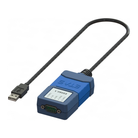
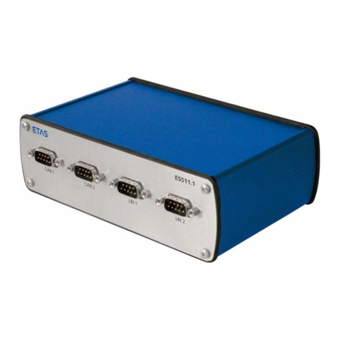
Fig. 3-1 ES584.1
The ES584.1 module supports CAN FD (CAN flexible date rate) and is suitable for
numerous applications, both in the classic CAN environment and in the CAN FD
environment.

ES584.1 – User’s Guide 14
ETAS Hardware Description
Together with the application software INCA and ODX-LINK from ETAS permits
the ES584.1 access to the CAN and LIN bus for measurement, calibration and
diagnostics.
The ES584.1 can be connected to a vehicle's CAN bus via the diagnostics service
interface.
When validating the vehicle diagnostics, the module can be used together with
ODX-LINK, the INCA add-on for ECU diagnostics, as an interface for OBD-on-
CAN, as well as to read and delete diagnostics error codes (DTCs). A separate
diagnostic service tool is not required in these cases.
The ES584.1 module offers an open SAE J2534-compliant pass-through inter-
face for vehicle diagnostics and flash programming.
The module supports all protocols used by INCA, such as CCP, XCP, KWP-on-
CAN and UDS. The CCP and KWP-on-CAN (ISO 14230/ISO 15765) protocols are
only supported in classic CAN mode.
The costs for installation and configuration of the affordable module are mini-
mal, and an external voltage supply is not required.
3.2 Application Areas
The ES584.1 can be used for the following tasks:
• Recording and capturing communication data
• Calibration of ECUs via the CAN FD bus interface
• ECU diagnostics via the CAN bus interface and J2534 pass-through inter-
face
• Vehicle diagnostics and reprogramming via a J2534 pass-through inter-
face using application software from third-party providers
• Flash programming of ECUs
• Connection of ETAS ES3xx modules, as well as modules from third-party
manufacturers, to the INCA PC via their CAN interface (e.g. Ipetronik or
csm modules)
• Integration of the module into the BUSMASTER open source software or
via EBI-IP into application software from third-party manufacturers

ES584.1 – User’s Guide 15
ETAS Hardware Description
3.3 Properties
The most important properties of the ES584.1 CAN FD and LIN Bus Interface USB
Module at a glance:
• 1 CAN/CAN FD interface
– CAN operating modes
CAN high-speed
CAN FD
– CAN protocols
CAN V2.0a (standard 11-bit identifier)
CAN V2.0b (extended 29-bit identifier)
ISO-compliant CAN FD and non-ISO-compliant CAN FD
CAN channel isolated from the USB port
– Multi-client access to the same CAN channel
Max. two clients can access the device
Two clients per channel
• DSUB connector in accordance with "CAN in Automation" (CiA)
• One LIN interface
• Simple and direct connection to a USB port
• No external voltage supply necessary
• Synchronization of the measuring channels with INCA
• Fully integrated in the ETAS tool chain – supported by INCA/INCA-EIP,
INTECRIO, ASCET-RP, HSP
• Module compatible with vehicles, suitable for use in the development
environment and in the passenger compartment of motor vehicles
Complete specifications for the ES584.1 module can be found in chapter 6
on page 33.

ES584.1 – User’s Guide 16
ETAS Hardware Description
3.4 Function Groups
bpRUQKN
CAN
LIN
CAN FD
Transceiver Controller
LIN
Transceiver
LIN
Controller
Microcontroller
LED
USB Interface
Isolation USB 2 .0
CAN FD / CAN
Fig. 3-2 ES584.1 block diagram
3.5 CAN FD Interface
CAN FD (CAN flexible data rate) is an improved, backward compatible CAN pro-
tocol. It differs from CAN mainly in the expansion of the useful data per message
from 8 to 64 bytes, higher transmission rates of up to 8 Mbit/s and longer check-
sums, which increase the reliability of transmission. CAN FD covers the demand
for a higher bandwidth for networks in the automotive industry. At the same
time, CAN FD nodes can easily be integrated into the existing CAN infrastructure.
The ES584.1 CAN FD and LIN Bus Interface USB Module has a CAN interface
CAN on its nine-pin DSUB socket. The CAN interface is an independent CAN
channel with its own CAN controller. It is isolated from the USB port of the
ES584.1.
3.5.1 Operating Modes
The CAN interface can be operated in high-speed CAN operating mode or in
CAN FD operating mode (CAN flexible data rate). The ES584.1 module supports
both ISO-compliant and non-ISO-compliant CAN FD.
The CAN interface can be configured in the application software for the follow-
ing operating modes:
• CAN
• ISO-compliant CAN FD
• Non-ISO-compliant CAN FD.
3.5.2 Time Stamp
The ES584.1 time stamps the CAN messages. The INCA application software syn-
chronizes the measurement data recorded by the ES584.1 module with signals
from other ECUs and measuring modules with high precision.
3.5.3 Feature
The CAN applications supported by the ES584.1 are located in an overview in
chapter 6.7.2 on page 39.
3.5.4 Bus Terminating Resistor
The CAN interface requires the use of bus terminating resistors in both operating
modes.

ES584.1 – User’s Guide 17
ETAS Hardware Description
According to the CAN specification, one bus terminating resistor of 120 ohm is
required at each of the two open ends of the bus. It must be connected to the
cable or the plug.
ETAS offers cables and terminating resistors of 120 ohm to set up CAN net-
works.
Some CAN networks are already terminated (for example in a vehicle), so no
additional termination is required.
3.5.5 Minimum Requirements for the CAN Connection
At least the following connections are required in order to establish a connection
to the CAN network:
• Pin 2 CAN Low
• Pin 7 CAN High
• Pin 6 or Pin 3 GND (either one of the pins can be connected)
The ground connection (GND) must be identical to the ground connection of the
other CAN nodes on the bus.
Note

ES584.1 – User’s Guide 18
ETAS Hardware Description
3.6 LIN Interface
The LIN interface is electrically isolated from the other interfaces of the module
and also protected against overload or misuse.
3.6.1 Operating Modes
The two clients of the LIN interface (see chapter "Multi-Client Support"
on page 21) can either be operated in the LIN master operating mode or in the
LIN slave operating mode. The following configurations are possible:
• Client 1: LIN master or LIN slave and
• Client 2: LIN slave
The operating mode is selected in the application software.
3.6.2 Feature
The LIN applications supported by the module are listed in an overview in chapter
6.7.2 on page 39.
3.6.3 Voltage Supply on the LIN Bus
LIN_GND
9
3
7
LINLIN_UBA TTDSUB-9
Fig. 3-3 Voltage supply on the LIN bus (pin assignment on the CBCF100
cable)
12 V LIN systems
In 12 V LIN systems, the LIN node of the ES584.1 module can either be supplied
externally by the LIN bus or internally by the module with the LIN reference volt-
age VBAT.
24 V LIN systems
In 24 V LIN systems, the LIN node of the ES584.1 module can only be supplied
externally by the LIN bus with the LIN reference voltage VBAT.
Supplying external LIN nodes
The module is not designed for the supply of external nodes on the LIN bus.
Selecting the voltage supply
An internal pull-up resistance can be switched to the LIN interface of the module
as master resistance. Switching of the master resistance of the LIN interface can
be configured in the application software.

ES584.1 – User’s Guide 19
ETAS Hardware Description
Recommendation
To maintain the reference level (and thereby identical switching thresholds) at
the individual nodes on the LIN bus, the LIN transceivers (physical layer) of all
nodes on the bus should be operated with the same voltage.
We therefore recommend powering all nodes on the LIN bus with the external
voltage that also powers the other bus participants (LIN VBAT, see Fig. 3-3
on page 18).
At the same time, this ensure compliance with safe switching thresholds in each
operating state of the LIN system (e.g. during vehicle cold starts).
If there is no access or no possibility of using the LIN VBAT voltage as reference
and supply voltage, the LIN transceivers of the dedicated LIN node of the ES584.1
can be supplied by a switchable internal voltage source of the module.
This internal supply voltage is not routed outside via the CAN/LIN plug connec-
tor.
3.7 USB Port
The module is permanently connected using a cable with type A USB connector
for connection to the USB port of a PC or a drive recorder.
The module must be operated directly at the USB port of a PC, a drive recorder
or an active hub, whose USB interface meets the requirements stated in the
table in chapter 6.7.1 on page 37.
The use of USB cables to extend the connection between ES584.1 and the PC
or drive recorder is not permitted.
3.8 Power Supply
The ES584.1 module is powered via the USB 2.0 port of a PC or a drive recorder.
The module does not require an external power supply. Information on the
requirements for the PC's USB port can be found in chapter 6.7.1 on page 37.
3.9 Y-Cable
A Y-cable (CBCF100, see chapter 7.1 on page 43) allows the CAN and LIN inter-
face of the ES584.1 module to access vehicle buses or ECUs.
Note

ES584.1 – User’s Guide 20
ETAS Hardware Description
3.10 Operating State Display
Fig. 3-4 ES584.1 LEDs
The ES584.1 is equipped with five LEDs for displaying the module's operating
state, as well as for displaying the function of the two CAN and LIN interfaces
(see Fig. 3-4 on page 20):
LED Display Description
CAN Flashing yellow Communication on the CAN interface
Off Communication on the CAN interface inter-
rupted
Red Communication error on the CAN interface
BUSY Blue The module is currently in the boot phase or a
firmware update is being performed. Do not
disconnect the module from the PC!
Off Standard operation
ON Green The module is switched on
Off The module is switched off
ER Red The boot process was not successful or the
module encountered a software error.
Restart the module.
Off No error
LIN Flashing yellow Communication on the LIN interface
Off Communication on the LIN interface inter-
rupted
Red Communication error on the LIN interface
Table of contents
Other ETAS Control Unit manuals
Popular Control Unit manuals by other brands

Siemens
Siemens SIRIUS 3RK3 Original operating instructions

Fairchild
Fairchild 74-13A instruction manual

Zoning
Zoning Zity Quick installation manual

Faraday
Faraday MPC-6000 Installation, operation and maintenance manual

Viessmann
Viessmann LANZ Bulldog Operation manual

Mitsubishi
Mitsubishi M80 series Connection and set up manual