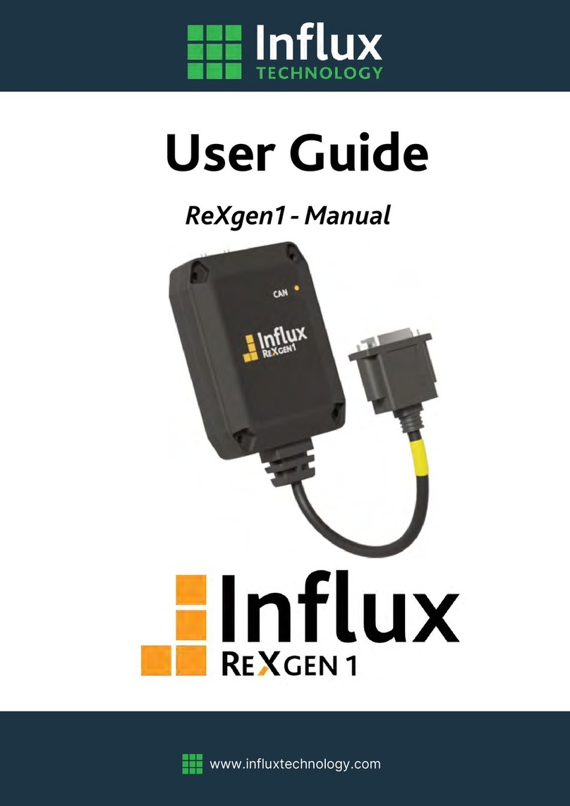
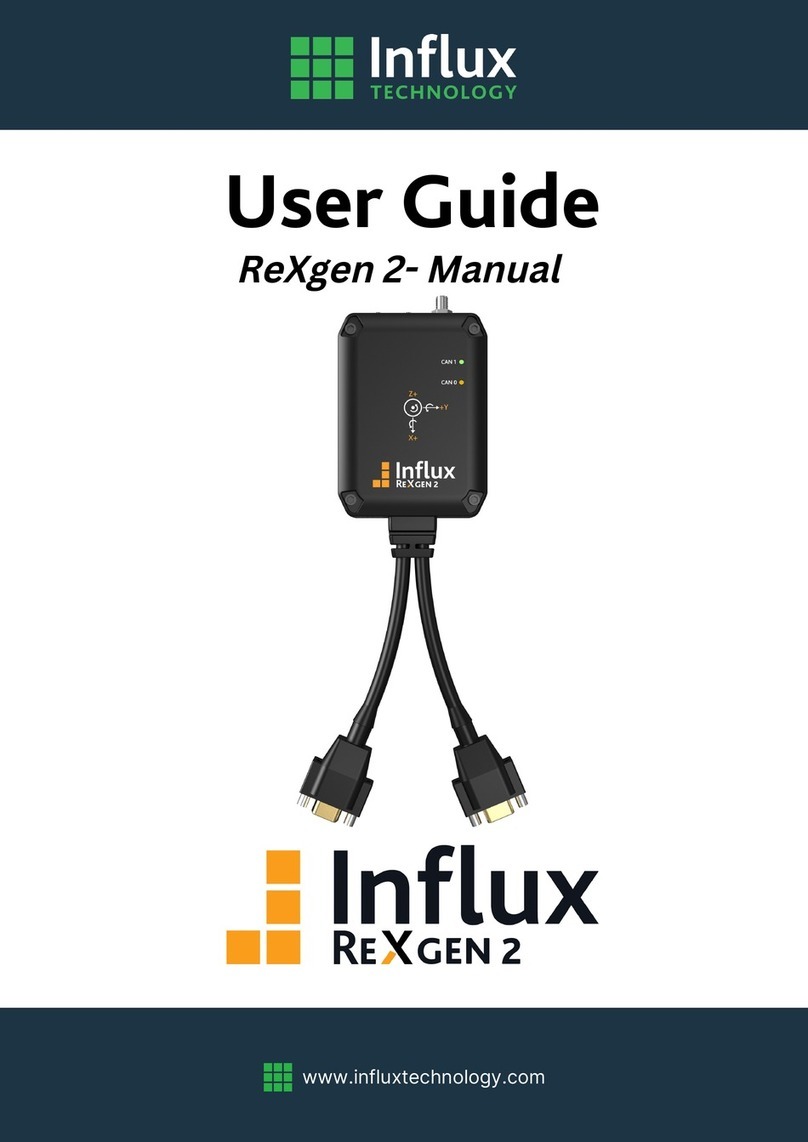
Influx Technology ReXgen User manual

www.influxtechnology.com
User Guide
ReXgen-Manual

© 2020 Influx Technology | Version 1.2
ABOUT THIS MANUAL
This document provides a brief idea on the usage, safety precautions, installation procedures and operation of the
Influx ReXgen2. This document is intended for professional engineers as well as academic researchers, allowing them
to understand the concept of operating the device and to integrate this knowledge into systems with components of
other manufacturers.
DISCLAIMER
Translation of the original Product Manual ReXgen2.
Version
Date
Remarks
1.0
21-10-2020
First official version
1.1
02-02-2021
Minor Changes
1.2
20-04-2021
Added Certifications
Table 1: Version Details
COPYRIGHT & LICENSE AGREEMENT
The content of this document including all brands and trademarks and possibly protected by third-party rights are
subject without limitation to the terms of the valid trademark law and intellectual property rights of their respective
registered owner.
© 2020 INFLUX TECHNOLOGY. All rights reserved.
CONTACT ADDRESS
Influx Technology Ltd
Office 22, Building 03, Millbrook Proving Ground
Bedford, MK45 2JQ, United Kingdom
Telephone: +44 (0) 1525 842504,
Sales: sales@influxtechnology.com
Support: support@influxtechnology.com
www.influxtechnology.com

© 2020 Influx Technology | Version 1.2
SAFETY INSTRUCTIONS
▪Always ensure that the device is installed, connected, and commissioned by a qualified professional by
following all safety norms.
▪Disconnect the device completely before handling it and disconnect any independently supplied output load
circuits.
▪Do not connect the housing to Ground externally. This will suspend the reverse voltage protection of the
power supply. Applying a reverse voltage in this case will destroy the supply circuits.
▪Provide all the device connectors with plugs and any protection caps required to ensure protection class
IP65.
▪Never immerse the device in water or other liquids.
▪The device must only be repaired by the manufacturer.
▪Keep substances that contain solvents away from the type label.
The following formatting and symbols will help you recognize the purpose of each paragraph:
Severe injury or death. Probability: possible
Slight or medium injury. Probability: possible
Property damage
•Important usage instructions/notes/limits.
Notes
DANGER
WARNING
CAUTION
ATTENTION!

© 2020 Influx Technology | Version 1.2
Table of Contents
ABOUT THIS MANUAL..................................................................................................................................................... 2
DISCLAIMER.................................................................................................................................................................... 2
COPYRIGHT & LICENSE AGREEMENT .............................................................................................................................. 2
CONTACT ADDRESS......................................................................................................................................................... 2
SAFETY INSTRUCTIONS ................................................................................................................................................... 3
1. OVERVIEW OF THE DEVICE .....................................................................................................................................6
1.1 GENERAL INFORMATION ................................................................................................................................ 7
1.1.1 DEVICE ELEMENTS................................................................................................................................... 7
1.1.2 PRODUCT DRAWINGS ............................................................................................................................. 7
1.1.3 TECHNICAL SPECIFICATION ..................................................................................................................... 8
1.1.4 ELECTRICAL DATA.................................................................................................................................... 9
1.1.5 INTENDED USE ........................................................................................................................................ 9
1.1.6 LIABILITY & WARRANTY ........................................................................................................................ 10
1.1.7 CONFORMITY ........................................................................................................................................ 10
1.2 DEVICE KIT..................................................................................................................................................... 10
1.2.1 HARDWARE........................................................................................................................................... 10
1.2.2 SOFTWARE ............................................................................................................................................ 10
1.3 SERVICE & SUPPORT ..................................................................................................................................... 11
2. HARDWARE & FUNCTIONALITY............................................................................................................................. 11
2.1 FUNCTIONS ................................................................................................................................................... 11
2.1.1 RECORDING CAN/CAN FD DATA............................................................................................................ 11
2.1.2 RECORDING LIN DATA........................................................................................................................... 11
2.1.3 RECORDING GNSS DATA........................................................................................................................ 11
2.1.4 RECORDING ACCELEROMETER & GYROSCOPE DATA ............................................................................ 11
2.1.5 DIGITAL & ANALOG INPUT FUNCTIONS................................................................................................. 11
2.2 HARDWARE................................................................................................................................................... 12
2.2.1 INSTALLATION.......................................................................................................................................12
2.2.2 ENCLOSURE........................................................................................................................................... 13
2.2.3 CABLES .................................................................................................................................................. 13
2.2.4 INDICATOR ELEMENTS –LED’S.............................................................................................................. 14
2.2.5 ACCESSORIES.........................................................................................................................................15
3. GETTING STARTED ................................................................................................................................................ 15
3.1 CONNECTING THE DEVICE............................................................................................................................. 15

© 2020 Influx Technology | Version 1.2
3.1.1 POWER.................................................................................................................................................. 15
3.1.2 CAN / CAN FD........................................................................................................................................15
3.1.3 ANALOG & DIGITAL INPUT .................................................................................................................... 16
3.1.4 USB........................................................................................................................................................ 16
3.2 SOFTWARE INSTALLATION............................................................................................................................ 16
3.3 DRIVER INSTALLATION .................................................................................................................................. 18
3.4 FIRMWARE UPDATE...................................................................................................................................... 19
4. ANNEXURES .......................................................................................................................................................... 20
4.1 DIGITAL INPUT FUNCTION ............................................................................................................................ 20
4.2 CERTIFICATIONS............................................................................................................................................ 21
FCC........................................................................................................................................................................ 21
CE.......................................................................................................................................................................... 22
ROHS..................................................................................................................................................................... 23
4.3 CAN OVERVIEW............................................................................................................................................. 24

© 2020 Influx Technology | Version 1.2
1. OVERVIEW OF THE DEVICE
This chapter gives an overview of the device, its operating elements and functions as well as the
intended use of the device.
I
Along with the free, user-friendly configuration software, the standalone ReXgen logger comes with
the following advantages:
▪Extreme level of compactness –pocket size
▪Tolerable to harsh environments with IP65 rating
▪Secure data storage with an internal eMMC
▪Supports CAN, CAN FD & LIN buses
▪Supports CAN monitoring RAW CAN signals, SAE J1939
▪Sleep modes with wake up on CAN & wake up on movement
▪Most advanced trigger & filter conditions
▪In-built gyroscope & accelerometer modules
▪2 x digital & 2 analog inputs
▪Up to 18 Hz rate GNSS module
▪Micro USB 2.0 PC interface
▪Internal temperature sensor
▪CAN error logging
Available Models
Model
eMMC Storage
CAN/CAN FD
Analog I/P
Accelerometer & Gyroscope
GNSS
INF2110
8 GB
2
2
No
No
INF2111
16 GB
2
2
No
No
INF2112
32 GB
2
2
Yes
Yes
INF2113
32 GB
2
2
Yes
Yes (Dead Reckoning)

© 2020 Influx Technology | Version 1.2
1.1 GENERAL INFORMATION
1.1.1 DEVICE ELEMENTS
1 –External GNSS antenna connector.
5 –Mounting Holes.
2 –Micro USB connector.
6 –Channel 1 Connector.
3 –Channel 1 LED.
7 –Channel 0 Connector.
4 –Channel 0 LED.
1.1.2 PRODUCT DRAWINGS

© 2020 Influx Technology | Version 1.2
1.1.3 TECHNICAL SPECIFICATION
Functions
ReXgen 2
ReXgen 2 IMU
CAN Interfaces
2 x CAN/CAN FD
ISO 11898-1: Compliant with CAN (up to 1 Mbit/s)
ISO & Bosch CAN FD (up to 8 Mbit/s)
Conforms to CAN protocol version 2.0 - part A, B
Max 20000 mps
Meets the requirements of ISO 11898-2:2016 & ISO 11898-5:2007 physical
layer standards
CAN/CAN FD Functions
Supports custom baud rates
CAN/CAN FD Bit timing selection
SAE J1939 support (Source Address, Destination Address & PGN Filters)
Silent Mode Configurable
CAN DBC Support
CAN frame error detection
LIN Interface
1 x LIN (up to 20 K Baud with LIN-Compatible Output Driver)
Inputs
2 x Digital and 2 x Analog
Positioning & IMU Sensors
GNSS
NA
Up to 18 Hz rate
GNSS Receiver Type
NA
72-channel, GNSS L1C/A, SBAS
L1C/A, QZSS L1C/A, QZSS L1-SAIF,
GLONASS L1OF, BeiDou B1I , Galileo
E1B/C
Position Accuracy
NA
2.0 m CEP*
Acquisition
NA
Cold starts: 26s
Reacquisition: 2 s
Antenna
NA
External
Accuracy
NA
Velocity: 0.05m/s
Heading: 0.3 degrees
Altitude: not specified
Accelerometer
NA
±2/±4/±8/±16 g full scale
Gyroscope
NA
±125/±250/±500/±1000/±2000 dps
full scale
PC Interfaces
Rugged Micro USB 2.0
Data Storage Capability
8 or 16 GB Inbuilt eMMC storage
32 GB Inbuilt eMMC storage
Supported Protocols
CAN Monitoring (RAW CAN signals, SAE J1939 support)
LEDs
2
Triggering
Trigger on CAN ID, CAN Signal, Digital Input.
Trigger on DM1 counter.
Data Storage format
FAT32, Log files accessible via ReXdesk software
File Format Supported
ASAM MDF (.mf4), CSV, MATLAB, ASC, BLF
Data Logger Configuration
Supplied with Influx ReXdesk configuration software, XML based

© 2020 Influx Technology | Version 1.2
Analog Input
Number of channels
2 x Bipolar single-ended inputs
Range
+/- 10 V
Resolution (ADC)
12 Bit
Max sampling rate
1 kHz
Input Impedance
> 50 K Ohms
Safe Applied Voltage
+/- 28 V
Digital Input
Number of channels
2 x Unipolar single-ended inputs
Input Switching Thresholds
Low < 0.8 V, High > 2.5 V (up to 28V)
Safe Applied Voltage
+/- 28 V
1.1.4 ELECTRICAL DATA
BUS & Signals
Operating Voltage
Power supply - OBD
+4.5 to +31V
Power supply - USB
+4.5 to +5.5V
CAN FD
+2 to +3V
LIN
0 to +24V
Digital Input
0 to +28V
Analog input
+/- 10V
Function
Description
Transceiver Protection
Bus fault protection: ±58 V
Thermal-shutdown protection (TSD)
Under-voltage protection
Enclosure
PC+ ABS
IP Rating
IP65
Dimension
L - 100 mm, W - 73.5 mm, H –27.4 mm
Weight
220164 Grams
Mounting Holes
4 mounting holes and screws
Stackable
Yes
Environmental Tolerance
Working temperature -40degC to +85degC; Humidity max 90%
Power Saving
Wake Up On CAN, Power Down Mode, Sleep Modes,
Wake Up On Movement
Power Consumption
Normal Operation: 87 mA at 12 V
Power Down Mode: <2 mA
*CEP - circular error probable
1.1.5 INTENDED USE
The ReXgen2 is one of the most compact, pocket-sized data loggers suitable for automotive and
various industrial applications. The device is designed to log data continuously for hours from a CAN
bus and simultaneously save it to the embedded SD memory card. The device is tolerable to all
harsh environments that require an IP65 class protection. It can be easily mounted and integrated
with your vehicle /machine.

© 2020 Influx Technology | Version 1.2
1.1.6 LIABILITY & WARRANTY
Influx Technology assumes no liability for damages caused by normal wear, installation errors,
operating or maintenance faults. This is also applicable when the user modifies the devices, any
accessories, or the software without the prior approval of Influx Technology.
1.1.7 CONFORMITY
For detailed information on the respective tests, see Chapter Certifications.
The device meets the following standards and legal requirements:
Compliance with CE
This device complies with the directives, standards and normative documents listed in chapter
Certifications.
Compliance with FCC
This device complies with the directives, standards and normative documents listed in chapter
Certifications.
Compliance with ROHS
This device complies with the directives, standards and normative documents listed in chapter
Certifications.
1.2 DEVICE KIT
1.2.1 HARDWARE
Packaging will contain the following components:
INF 2110/INF 2111
▪1x Rexgen2 with integrated cable
▪1x Micro USB
INF 2112/INF 2113
▪1x Rexgen2 with integrated cable
▪1x Micro USB
▪1x GNSS Antenna with 5M long cable
1.2.2 SOFTWARE
ReXgen2 device will be supplied with a freely distributed configuration and data retrieval software, ReXdesk.
The software can be downloaded from our website, www.influxtechnology.com.

© 2020 Influx Technology | Version 1.2
1.3 SERVICE & SUPPORT
Please visit the support section in our website www.influxtechnology.com.
The latest versions of the drivers, software, firmware, and documentations are available on our website.
2. HARDWARE & FUNCTIONALITY
In this chapter, you will find Information on the device functionality and hardware.
2.1 FUNCTIONS
FUNCTION
ReXgen2 (INF 2110/2111)
ReXgen2 IMU (INF 2112/2113)
CAN/CAN FD Data Logging
Yes
Yes
Digital and Analog Input
Yes
Yes
LIN Data Logging
Yes
Yes
GNSS Data Logging
-
Yes
Accelerometer and Gyroscope Logging
-
Yes
Table 1: Device Functions
2.1.1 RECORDING CAN/CAN FD DATA
The device can be effectively used to log data on field tests as well as on a bench via CAN/CAN FD
interfaces. The device supports all standard CAN/CAN FD baud rates. ReXdesk software also allows
the user to configure ReXgen with custom baud rates and modify advanced bit timings. ReXdesk
also allows the user to configure ReXgen with CAN & J1939 filters. All logged data is saved to the
secure embedded memory. The user can configure triggers based on CAN IDs, parameter values &
J1939 DM1 messages to start or stop logging.
2.1.2 RECORDING LIN DATA
The device can be effectively used to log data on field tests as well as on bench via LIN interfaces.
All logged data is saved to the embedded SD memory card.
2.1.3 RECORDING GNSS DATA
The device consists of an internal GNSS module and an external active antenna with a supply
voltage of 3V. This receiver can evaluate signals from the GNSS/QZSS, GLONASS, BeiDou and Galileo
satellites. GNNS data can be logged at sampling rates up to 18HZ.
*Applicable only for ReXgen2 IMU version
2.1.4 RECORDING ACCELEROMETER & GYROSCOPE DATA
The device consists of an internal accelerometer and gyroscope module. Acceleration output data
rate is up to 6664 Hz with vibration rate of ±2/±4/±8/±16 g at full scale. Angular output data rate of
gyroscope is up to 1666 Hz with ±125/±250/±500/±1000/±2000 dps at full scale.
*Applicable only for ReXgen2 IMU version
2.1.5 DIGITAL & ANALOG INPUT FUNCTIONS
The input function can be used, for instance, to log status information from devices, machines, and
sensors to directly determine and monitor switch and key states. You can record the data

© 2020 Influx Technology | Version 1.2
determined from the input functions, and it can be used for creating triggers for starting and
stopping logging.
2.2 HARDWARE
2.2.1 INSTALLATION
The contents below specify the conditions to be ensured for the operation of ReXgen2.
GROUNDING
Since it is not required to provide a common ground between nodes, it is possible to have ground
offsets between nodes. That is, each node may observe different single-ended bus voltages (common
mode bus voltages) while maintaining the same differential voltage. Operating a CAN system with large
ground offsets can lead to increased electromagnetic emissions. Steps must be taken to eliminate
ground offsets if the system is sensitive to emissions.
TERMINATION
ISO-11898 requires that the CAN bus have a nominal characteristic line impedance of 120Ω.
Therefore, the typical terminating resistor value for each end of the bus is 120Ω. Bus termination is
used to minimize signal reflection on the bus.
SUPPLY VOLTAGE
It is always recommended to keep the nominal voltage within the specified rate. The device also has
internal protection against low energy voltage events, that may occur as a result of supply wire
noise.
ISOLATION
CAN Bus and USB of the device is not isolated; care must be taken when plugging the USB to the
device. It is advised to remove the power supply to the device when the device is interfaced to a PC
via USB.
MOUNTING
Always ensure to mount the device in a way that minimizes vibration exposure and accounts for the IP
rating of the device. ReXgen is supplied with 4 screws to assist you with the mounting process.
•CAN Bus and USB Isolators can be purchased seperately.
Notes
WARNING

© 2020 Influx Technology | Version 1.2
ANTENNA
An external active antenna with a supply voltage of 3V is required for GNSS data logging. It is to be
ensured that the antenna is properly connected at all times and that it is not loose when the ReXgen
is powered on. Operation with a loose antenna or without the antenna entirely can lead to GNSS
data loss.
2.2.2 ENCLOSURE
The device is not intended for use without the enclosure.
2.2.3 CABLES
ReXgen comes with integrated cables, with a 9-pin D-Type connector. ReXgen is also available with
Rugged Automotive specification connectors; these are made as per request on bulk orders. Apart
from this the device will be supplied with a micro-USB cable and a GNSS antenna with an integrated
5M cable (INF2112/2113).
2.2.3.1 CONNECTOR PIN DETAILS
There are two connectors, a male and female 9-pin Standard D-Type connector.
Channel 0 Connector
PIN No DB9(Male with Nuts)
PIN Function PWR/CAN0/Digital/LIN
Pin 1
Digital 1
Pin 2
CAN/CAN FD 0 - Low
Pin 3
GND
Pin 4
LIN
Pin 5
Power GND
Pin 6
Digital 0
Pin 7
CAN/CAN FD 0 - High
Pin 9
Power Supply 5-31V
PIN No DB9(Female with Screws)
PIN Function CAN1/Clamp/Analog
Pin 1
GND A
WARNING
WARNING

© 2020 Influx Technology | Version 1.2
Channel 1 Connector
2.2.3.2 GNSS ANTENNA CONNECTOR
ReXgen uses an SMA female connector for the GNSS antenna.
2.2.4 INDICATOR ELEMENTS –LED’S
2 LEDs are installed on the ReXgen device for indicating the CAN/CAN FD logging activity.
LED 1 - Channel 0 - Green
LED 2 - Channel 1 - Amber
Blinking –Logging
Bold –Not logging, Configuration active.
LED 1 and LED 2 flashing alternatively - Reflashing in progress
•Connector needs to be tightened properly to make a proper connection, ensuring reliable operation.
•Each end of the CAN/CAN FD bus must be terminated with a 120 Ohm resistor across CAN H & CAN L.
•Do not short circuit any pins.
•Maximum safe applied voltage for analog and digital I/P is +/- 28 V.
Notes
Pin 2
CAN/CAN FD 1-Low
Pin 3
GND
Pin 4
Analog IN 0
Pin 5
GND A
Pin 6
Analog IN 1
Pin 7
CAN/CAN FD 1-High
Pin 8
Clamp-15
PIN No
PIN Function
Pin 1
Signal
Pin 2
GND

© 2020 Influx Technology | Version 1.2
2.2.5 ACCESSORIES
Accessory
Part Number
Description
CAN Isolator
-
External isolator for the CAN Bus.
USB Isolator
-
External isolator for the USB.
CAN Terminator
INF4310
120 Ohms D Sub 9 CAN Terminator.
OBD II TYPE-B Cable to 9-way D-Sub
INF4103
Cable for connecting to vehicle OBD port.
Multi power supply & CAN cable
INF4206
This cable uses the vehicle auxiliary power outlet or
banana plugs (battery) for the power supply.
3. GETTING STARTED
3.1 CONNECTING THE DEVICE
•The device must be installed, connected, and commissioned by a qualified technician.
•Ensure the power supply is disconnected before connecting the device.
•Only use components from the starter kits or the accessories supplied.
3.1.1 POWER
Power supply to the product is given using the connector A, using the male, 9-pin standard D-type connector.
3.1.2 CAN / CAN FD
ReXgen can be interfaced to the CAN/CAN FD bus from which data is to be logged using D-Sub 9 connector
A or connector B. The CAN-high and CAN-low from the vehicle or machine terminals must match the CAN-
high and CAN-low terminal of the ReXgen. ReXgen should be configured with the same baud rate as that
of the device to which it is interfaced.
•Connector needs to be tightened properly to make a proper connection, ensuring reliable operation.
•Do not short circuit any pins.
•Maximum safe applied voltage is +34V
Notes
•Connector needs to be tightened properly to make a proper connection, ensuring reliable operation.
•Each end of the CAN/CAN FD bus must be terminated with a 120 Ohm resistor accros CAN H & CAN L.
•Do not short circuit any pins.
•Maximum safe applied voltage is +28V.
•CAN/CAN FD bus is not isolated by default; isolating device can be purchased seperately.
Notes
ATTENTION!

© 2020 Influx Technology | Version 1.2
3.1.3 ANALOG & DIGITAL INPUT
ReXgen supports 2 analog inputs in the range of +/- 10 V. The 2 analog inputs are interfaced to the
ReXgen via a D-Sub 9 connector B. ReXgen also supports two digital inputs. The digital inputs are
interfaced to the ReXgen via a D-Sub 9 connector A.
3.1.4 USB
For configuration and test purposes, you can connect the device to a PC via the communication
gateway USB. The device is supplied with a standard Micro USB cable. Please note that the USB is not
isolated and an isolator can be purchased separately.
3.2 SOFTWARE INSTALLATION
Download the latest version of our ReXdesk software from the Influx Technology website.
Make sure you have installed the Microsoft Visual C++ Redistributable.
You can download it from the following link: https://www.microsoft.com/en-us/download/details.aspx?id=48145
To begin installation of the ReXdesk software, open the installer by running the set-up file.
•To continue with the installation of ReXdesk on
your system click ‘Next’.
•To cancel the installation at this stage, click
‘Cancel’. (No software will have been installed on
the system at this point.)
•Select the Folder in which you wish to install the
software; it is preferred to use the default location.
•Connector needs to be tightened properly to make a proper connection,ensuring reliable operation.
•Do not short circuit any pins.
•Maximum safe applied voltage is +28V
Notes
•Before proceeding with the installation, please ensure that you have acquired administrative
privileges.
Notes

© 2020 Influx Technology | Version 1.2
•Select the preference for computer user
installation, to determine which computer users
will have access to the ReXdesk software.
•Click ‘Next’ to continue with the installation
•To continue with the installation of ReXdesk on
your system click ‘Next’.
•Once the installation is complete, this window will
appear.
•Click ‘Finish’ to close the window. ReXdesk is now
successfully installed on your system.

© 2020 Influx Technology | Version 1.2
3.3 DRIVER INSTALLATION
To install the ReXgen driver, locate the ReXgen Drivers
installer from the start menu.
Run the ReXgenInstaller.exe file.
•To continue with the installation of ReXgen device
driver on your system click ‘Next’.
•To cancel the installation at this stage, click ‘Cancel’.
(No software will have been installed on the system
at this point.)
•Before proceeding with the installation, please ensure that you have acquired administrative
privileges.
Notes

© 2020 Influx Technology | Version 1.2
•Please Read the licence agreement carefully.
•Once you understand and accept the licence
agreement, please click ‘I accept the terms in the
licence agreement’ to be able to continue with the
installation of the driver. If you do not accept the
terms, please click ‘Cancel’ to stop the installation at
this point.
•Click ‘Next’ to continue the installation process.
•Once the installation is complete this window will
appear.
•Click ‘Finish’ to close the window. The ReXgen driver
is now successfully installed on your system.
3.4 FIRMWARE UPDATE
All newly released firmware updates will be available in
www.influxtechnology.com
Firmware can be updated using the Reflash option in the
ReXdesk software.

© 2020 Influx Technology | Version 1.2
4. ANNEXURES
This chapter contains technical data and certificates.
4.1 DIGITAL INPUT FUNCTION
The Digital Input Output pins will consider voltages below 0.8V to be low and above 2.5V to be high. Examples of
how you could utilise the I/O pins if configured as inputs are shown below.
•While reflashing, the LEDs on the device will flash alternatively, do not disconnect or change the
power source of the device during this process.
•The device will disconnect from the PC while it is reflashing. It will automatically reconnect once
reflashing is completed.
Notes
Other manuals for ReXgen
1
This manual suits for next models
1
Table of contents
Other Influx Technology Data Logger manuals
