Infors Multitron User manual
Operating Manual
2019-02-26
Multitron
Incubation Shaker
Dok-ID: 77408 / V.01.00 / Rev. 4.0 - Original

Infors AG
Headoffice, Schweiz
Rittergasse 27
CH-4103 Bottmingen
T +41 (0)61 425 77 00
F +41 (0)61 425 77 01
info@infors-ht.com
service@infors-ht.com
Infors GmbH
Dachauer Str. 6
D-85254 Einsbach
T +49 (0)8135 8333
F +49 (0)8135 8320
infors.de@infors-ht.com
Infors UK Ltd
The Courtyard Business Centre
Dovers Farm, Lonesome Lane,
Reigate
Surrey, RH2 7QT, UK
T +44 (0)1737 22 31 00
F +44 (0)1737 24 72 13
infors.uk@infors-ht.com
Infors Sarl
2, rue du Buisson aux Fraises
Bâtiment D13
F-91300 Massy
T +33 (0)1 69 30 95 04
F +33 (0)1 69 30 95 05
infors.fr@infors-ht.com
www.infors-ht.fr
Infors Benelux BV
Markweg 9-A, NL-6883 JL
Velp (GLD)
P.O. Box 125, NL-6880 AC
Velp (GLD)
T +31 (0)26 369 31 00
F +31 (0)26 369 31 09
infors.bnl@infors-ht.com
Infors USA Inc.
9070 Junction Drive, Suite D
Annapolis Junction, MD20701
T +1 301 362 3710 /
T +1 855 520 7277 (toll-free USA)
F +1 301 362 3570
infors.usa@infors-ht.com
www.infors-ht.us
Infors Canada
8350 rue Bombardier
Anjou, Quebec
Canada H1J 1A6
T +1 514 352 5095
F +1 514 352 5610
infors.ca@infors-ht.com
Infors Bio-Technology
(Beijing) Co., Ltd.
Room 505C, Building 106
Lize Zhongyuan
Wangjing New Industrial Zone
Chaoyang District, Beijing
100102 P.R. of China
T +86 10 51652068
F +86 10 64390585
info@infors-ht.com.cn
Infors South East Asia
16, 1st Floor, Taman City
MY-51200 Kuala Lumpur
Malaysia
T +603 625 771 81
F +603 625 067 48
info@infors-ht.com.my
Infors LATAM Ltda.
Rua Dr. Alceu de Campos
Conjunto 205
CEP: 04544-000
São Paulo – SP
Brasil
T +55 (11) 95304-0201
F +55 (11) 98585-5334
Infors.br@infors-ht.com
Contact details of our local dealers worldwide can be found
on our website.
www.infors-ht.com
Engineering and production in Switzerland

Multitron - Incubation Shaker
Table of Contents
25 February 2019 Page 1of 146
1General Information ...............................................................6
1.1 About this Manual ..........................................................6
1.2 Explanation of Special Notices ......................................7
1.2.1 Warning Notices .............................................7
1.2.2 Other Notices..................................................7
1.3 Equipment Identification (Standard Identification Plate) 8
1.4 Declaration of Conformity ..............................................8
1.5 Customer Service and Services ....................................8
2Safety and Responsibility .....................................................9
2.1 Intended Use, Incorrect Use and Misuse ......................9
2.2 Cultivation Vessels to Be Used....................................10
2.3 Qualified Personnel .....................................................12
2.3.1 Provider ........................................................12
2.3.2 User ..............................................................12
2.3.3 Operator .......................................................13
2.4 Unauthorised Persons .................................................14
2.5 Responsibility of the Provider ......................................14
2.6 General Hazards..........................................................14
2.6.1 Electrical Current..........................................15
2.6.2 Unauthorised Spare Parts and Accessories 15
2.7 Particular Hazards .......................................................15
2.7.1 Danger due to Hot Surfaces.........................16
2.7.2 Dangerous Gases ........................................16
2.7.3 Flammable or Explosive Substances ...........16
2.7.4 Corrosive or Toxic Substances ....................16
2.7.5 Pathogenic Organisms .................................17
2.8 Safety Features............................................................17
2.9 Warning Symbols on the Equipment ...........................18
2.10 Declaration of Decontamination...................................19
3Setup and Function..............................................................20
3.1 Setup of the Basic Unit ................................................20
3.2 Functions Installed by Default......................................24
3.2.1 Standard Function Shaking ..........................24
3.2.2 Standard Function Tempering (Heating)......27
3.3 Connections and Interfaces .........................................28
3.3.1 Mains Connection.........................................28
3.3.2 Alarm Connection.........................................28
3.3.3 Ethernet Interface.........................................29
3.4 Openings......................................................................29
3.4.1 Discharge Outlet...........................................29

Multitron - Incubation Shaker
Table of Contents
Page 2of 146 25 February 2019
3.4.2 Ventilation Opening ......................................30
3.4.3 Air Vents .......................................................30
3.5 Interior Lighting ............................................................31
3.6 Frames .........................................................................31
3.7 Operating and Indicating Elements..............................32
3.7.1 Main Switch ..................................................32
3.7.2 Operating Panel............................................32
3.8 Markings on the Equipment .........................................33
3.8.1 Identification Plate ........................................33
3.8.2 Identification of the Throw ............................33
4Options..................................................................................34
4.1 Cooling .........................................................................34
4.1.1 Internal Cooling.............................................34
4.1.2 External Cooling ...........................................36
4.1.3 Operating the Cooling Unit ...........................37
4.1.4 Specifications and Technical Data ...............37
4.2 Direct Steam Humidification.........................................38
4.2.1 Setup and Function ......................................38
4.2.2 Connection Conditions .................................39
4.2.3 Operating the Direct Steam Humidification ..40
4.2.4 Specifications and Technical Data ...............40
4.3 CO2Control..................................................................41
4.3.1 Setup and Function ......................................41
4.3.2 Connection Conditions .................................42
4.3.3 Operating the CO2Control............................42
4.3.4 Specifications and Technical Data ...............42
4.4 UV Decontamination ....................................................43
4.4.1 Setup and Function ......................................43
4.4.2 Operating the UV Decontamination..............43
4.4.3 Specifications and Technical Data ...............43
4.5 Removable Intermediate Base.....................................44
4.6 LED Lighting.................................................................45
4.6.1 Setup and Function ......................................45
4.6.2 Operating the LED Lighting ..........................45
4.6.3 Specifications and Technical Data ...............46
4.7 Darkening.....................................................................46
4.8 Analogue Output ..........................................................46
4.8.1 Setup and Function ......................................46
4.8.2 Connection Assignment................................47
4.9 Cable Pass-through .....................................................47
4.9.1 Setup and Function ......................................47

Multitron - Incubation Shaker
Table of Contents
25 February 2019 Page 3of 146
4.9.2 Using the Cable Pass-through .....................48
5Accessories ..........................................................................49
5.1 Trays ............................................................................49
5.1.1 Universal Table Tray ....................................49
5.1.2 Pre-Fitted Trays............................................50
5.1.3 Tray with «Sticky Stuff» Adhesive Matting ...55
5.2 Clamps and Other Holders ..........................................59
5.2.1 Clamps .........................................................59
5.2.2 Test Tube Holders........................................60
5.3 Box for Microtitre Plates...............................................61
5.4 Software.......................................................................64
5.4.1 eve®..............................................................64
6Installation ............................................................................65
6.1 Operating Conditions at the Installation Location ........65
6.2 Requirements for the Mains Connection .....................66
6.3 Minimum Distances to the Equipment .........................67
7Operation ..............................................................................69
7.1 Switching on the Equipment ........................................69
7.2 Loading the Equipment................................................69
7.2.1 Opening the Door .........................................69
7.2.2 Inserting and Removing the Tray .................70
7.2.3 Fitting the Holders ........................................73
7.2.4 Notices on Loading the Tray ........................75
7.3 Overview about the Display und Controls ...................76
7.3.1 Display Area .................................................77
7.3.2 Signs and Messages Regarding the Timer
Function........................................................78
7.3.3 Error, Warning, and Alarm Signs..................79
7.3.4 Operating Panel ...........................................80
7.4 Adjusting, Activating and Deactivating Parameters.....81
7.4.1 Overview about the Parameters...................81
7.4.2 Setting the Parameter Setpoints ..................84
7.4.3 Turning a Parameter On or Off.....................85
7.5 Timer Function .............................................................86
7.5.1 Overview.......................................................86
7.5.2 Programming the Timer - Single Change.....91
7.5.3 Programming the Timer - Cyclic Change .....96
7.5.4 Changing Timer Settings during Activated
Timer Function .............................................97
7.5.5 Changing Parameter Setpoint Values
during Activated Timer Function...................98

Multitron - Incubation Shaker
Table of Contents
Page 4of 146 25 February 2019
7.5.6 Stopping the Timer Function ......................100
7.6 Using eve®to Operate the Equipment .......................101
7.7 Settings Menu (Option Function) ...............................103
7.7.1 Setting the Upper Limit for the
Rotation Speed ...........................................103
7.7.2 Setting the Upper Limit for the
Temperature ...............................................104
7.7.3 Setting the Lower Limit for the
Temperature ...............................................104
7.7.4 Setting the Brake Force for Halting the
Table...........................................................104
7.7.5 Activating or Deactivating the Key Pad
Lock (with a PIN) ........................................105
7.7.6 Activating or Deactivating the Key Tone ....105
7.7.7 Setting the Interior Lighting.........................106
7.7.8 Activating or Deactivating the Timer
Function ......................................................106
7.7.9 Setting up Data Exchange via the
Ethernet ......................................................106
7.7.10 Setting the Height Above Sea Level
(Altimeter) ...................................................107
7.7.11 Activating or Deactivating the Door Alarm..107
7.8 Setting the Variable Throw.........................................107
7.9 Switching Off the Equipment......................................108
7.10 Behaviour in Case of Interrupted Power Supply........108
8Rectifying Faults ................................................................109
8.1 Alarm Messages ........................................................109
8.1.1 Parameter-Specific Alarm Messages .........109
8.1.2 Alarm Message RESTARTED....................111
8.2 Faults and Error Messages........................................111
8.2.1 Error Messages Explained .........................111
8.2.2 Fault Tables ................................................114
8.3 Replace Equipment Fuses .........................................118
8.4 Returning for Repair...................................................118
9Maintenance and Cleaning ................................................119
9.1 Maintenance...............................................................119
9.2 Cleaning and Disinfection ..........................................120
9.2.1 Cleaning......................................................120
9.2.2 Disinfection .................................................123
10 Transport and Storage.......................................................124
10.1 Transport....................................................................124
10.2 Storage.......................................................................124

Multitron - Incubation Shaker
Table of Contents
25 February 2019 Page 5of 146
11 Disassembly and Disposal................................................125
11.1 Disassembly...............................................................125
11.2 Disposal .....................................................................126
12 Technical Data and Specifications...................................127
12.1 Dimension Drawings..................................................127
12.2 Specifications of the Basic Unit .................................129
12.2.1 Weight and Dimensions .............................129
12.2.2 Electrical Connection and Power Values ...130
12.2.3 Connections and Interfaces........................130
12.2.4 Interior Lighting...........................................131
12.2.5 Material.......................................................131
12.2.6 Emissions ...................................................131
12.2.7 Operating Conditions..................................131
12.2.8 Protection Type ..........................................131
12.2.9 Operating and Auxiliary Materials ..............132
12.3 Specifications of Standard Parameters .....................132
12.3.1 Rotation Speed Parameter (Shaker Drive) 132
12.3.2 Temperature Parameter (Heating and
Ventilation)..................................................134
12.4 Specifications of the Options .....................................134
12.4.1 Internal Cooling ..........................................134
12.4.2 External Cooling .........................................136
12.4.3 Direct Steam Humidification .......................136
12.4.4 CO2 Control.................................................138
12.4.5 UV Decontamination ..................................139
12.4.6 LED Lighting ...............................................139
13 EC-Declaration of Conformity...........................................140
14 Index....................................................................................141

Multitron - Incubation Shaker
General Information
Page 6of 146 25 February 2019
1 General Information
1.1 About this Manual
This manual enables the safe and efficient handling of the equip-
ment.
All the information and instructions in this operating manual comply
with the current standards, legal regulations, the latest technologi-
cal and scientific developments and the knowledge gained from the
manufacturer’s many years of experience in this field.
This operating manual is a component part of the equipment.
It must be kept near to the equipment and must be accessible
to the operators at all times.
The users must read the operating manual thoroughly and fully un-
derstand its contents before beginning any work.
Adhering to all the safety and operating instructions in this manual
is essential to ensure that work is carried out safely.
The scope of delivery may differ from the explanations, descrip-
tions and figures in this operating manual due to special designs,
additional options specified on ordering and the latest tech-
nical/mechanical modifications.
This manual contains illustrations to aid general understanding.
These may differ from the actual equipment as supplied.

Multitron - Incubation Shaker
General Information
25 February 2019 Page 7of 146
1.2 Explanation of Special Notices
1.2.1 Warning Notices
Warning notices in this manual are indicated by a coloured bar and
begin with a signal word that signifies the degree of the hazard.
DANGER
The signal word “DANGER” indicates a dangerous situation that
will lead to severe or even fatal injuries if not avoided.
WARNING
The signal word “WARNING” indicates a potentially dangerous
situation that may result in severe or even fatal injuries if not
avoided.
CAUTION
The signal word “CAUTION” indicates a potentially dangerous
situation that may result in minor injuries if not avoided.
1.2.2 Other Notices
ATTENTION
The word “ATTENTION” on a blue bar indicates a situation that
may result in significant damage to property if not avoided.
INFORMATION
Texts located below a grey bar bearing the notice “INFOR-
MATION” provide useful tips and recommendations for ensuring
efficient, fault-free operation of the equipment.
Multitron - Incubation Shaker
General Information
Page 8of 146 25 February 2019
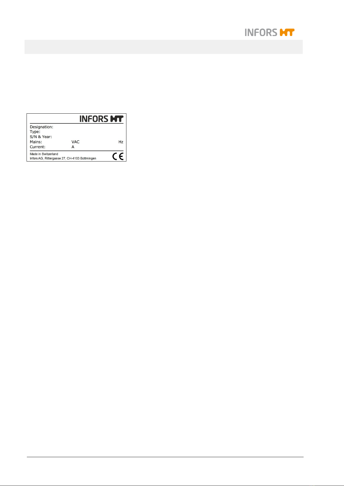
1.3 Equipment Identification (Standard Identification Plate)
The identification plate is designed to allow clear identification of
the equipment. It contains the following information:
Manufacturer name and address
Designation = Category of equipment
Type = Equipment type (name)
S/N = Serial number
Year = Year of manufacture
Mains = Nominal voltage and frequency
Current = Max. current consumption
CE marking
1.4 Declaration of Conformity
The equipment is in compliance with the essential requirements of
the following Directives:
Machinery Directive 2006/42/EC
EMC Directive 2014/30/EU
The Declaration of Conformity according to EC Machinery Directive
2006/42/EC, annex II 1 A is attached to the operating manual (see
chapter 13 "EC-Declaration of Conformity", page 140).
1.5 Customer Service and Services
Our Customer Service is at your disposal for technical advice and
specialist enquiries. For contact information, see page 2.
Due to their familiarity with the potential applications of the equip-
ment, the Customer Service team is able to provide information on
whether the equipment can be used for a specific application or
modified to handle the planned process.
Experience of working with the equipment will be published semi-
regularly on the manufacturer’s website in the form of “application
notes”.
Furthermore, our colleagues are always interested in new infor-
mation and experiences resulting from user’s applications for the
equipment that may be valuable for the continued development of
our products.

Multitron - Incubation Shaker
Safety and Responsibility
25 February 2019 Page 9of 146
2 Safety and Responsibility
This section describes general considerations relating to user
safety that must be taken into account when working with the
equipment.
In the remaining sections, warning notices are used only to high-
light particular hazards directly arising from the actions being de-
scribed in the section in question.
It is essential to read the operating manual carefully – espe-
cially this section and the warning notices in the text – and to
follow the instructions therein.
This section also refers to areas that are the responsibility of the
provider due to certain risks arising from particular applications for
which the equipment is used deliberately and with full awareness
of the associated risks.
2.1 Intended Use, Incorrect Use and Misuse
Depending on its features, the equipment is designed to be
used as an incubation shaker for cultivating microorganisms
or cell cultures only under the following conditions:
Cultivation of non-pathogenic microorganisms or cell
cultures of risk category 1 in a biotechnology labora-
tory of biological protection level 1.
Cultivation of pathogenic microorganisms or cell cul-
tures of risk category 2 in a biotechnology laboratory
of biological protection level 2.
When using the equipment in protection level 2, users are re-
sponsible for taking appropriate protective measures to en-
sure that organisms cannot escape uncontrollably due to
flask breakage, unintentional detaching of the sterile seal or
similar.
WARNING
The equipment is designed and constructed exclusively for the
intended use described above.
Each instance of non-conventional use is considered as misuse
and may lead to dangerous situations.

Multitron - Incubation Shaker
Safety and Responsibility
Page 10 of 146 25 February 2019
Intended use also includes following all the instructions in this man-
ual, especially those relating to:
The installation site
Use of suitable cultivation vessels
User qualifications
Permissible parameter setpoints
Correct operation and maintenance
Any failure to observe the requirements specified in this manual
shall be deemed incorrect use, in particular, use of inappropriate
cultivation vessels and/or unsuitable holders at speeds that are too
high.
Any use of the equipment outside the scope of the intended use as
described above shall be deemed misuse. This also applies to ap-
plications for which the equipment is not designed, especially the
following:
The equipment is not protected against explosions. Use and
manufacture of explosive gases as well as operating the
equipment in the Ex area are therefore not permitted.
The equipment is not designed to sufficiently protect its users
if pathogenic organisms escape uncontrollably. Cultivation of
pathogenic organisms of risk categories 3 and 4 is therefore
not permitted.
To use the equipment for special applications not covered by con-
ventional, intended use, the equipment must be modified and certi-
fied accordingly by the manufacturer.
Any use of the equipment outside of a biotechnology laboratory,
i.e. in any environment in which the conditions required for the
safety of users cannot be met or cannot be met to their full extent,
shall also be deemed misuse.
2.2 Cultivation Vessels to Be Used
Significant forces are applied to cultivation vessels, in particular in
case of large vessels and high speeds. Hence, the cultivation ves-
sels used are particularly significant in relation to user safety.
ATTENTION
Use of unsuitable or defective cultivation vessels can lead to
glass breakage and therefore damage to property.

Multitron - Incubation Shaker
Safety and Responsibility
25 February 2019 Page 11 of 146
Approved cultivation vessels
The equipment has been designed for use with the following ves-
sels using the holders designed specifically for them:
Erlenmeyer flasks up to 5,000 mL made of borosilicate glass
(e.g. Schott Duran®) or high-grade plastic, such as polycar-
bonate (z. B. Corning®) etc.
Fernbach flasks up to 3,000 mL made of borosilicate glass
(e.g. Schott Duran®) or high-grade plastic, such as polycar-
bonate (z. B. Corning®) etc.
Other vessels with the holders designed for them:
Test tubes
Centrifuge tubes
Microtitre plates
Deep well plates
To avoid the vessels coming out of the clamps at very high speeds,
they might have to be secured using cable ties underneath the
springs or some other suitable measure.
Cultivating organisms of risk category 2
When cultivating pathogenic organisms of risk category 2, special
measures must be taken to stop the organisms from escaping. The
user is responsible for this.
When using the equipment under protection category 2, stainless
steel clamps of the correct size must be used to affix the flasks.
Due to limited resistance to disinfectants as well as the risk of unin-
tentional detaching of flasks, «Sticky Stuff» adhesive matting is not
suitable for this purpose.
We further recommend using disposable plastic flasks with screw
tops and filter membranes. We recommend using sticky tape to
secure the lid against loosening unintentionally. Using glass flasks
with cotton wool or paper plugs is not sufficiently safe.
Trays with «Sticky Stuff» adhesive matting
INFORMATION
For trays with «Sticky Stuff» adhesive matting, special provi-
sions apply in relation to maximum permitted speeds. These
must be observed to prevent cultivation vessels from detaching.
For detailed information see chapter 5.1.3 "Tray with «Sticky
Stuff» Adhesive Matting", page 55.

Multitron - Incubation Shaker
Safety and Responsibility
Page 12 of 146 25 February 2019
2.3 Qualified Personnel
Due to the complexity of the equipment and the potential risks aris-
ing from its operation, the equipment may only be used by quali-
fied, specialist personnel.
2.3.1 Provider
The term “provider” applies to all persons who are responsible for
making the equipment and the necessary infrastructure available.
These persons may also be included in the group of people known
as “users”, though this is not always the case.
Irrespective of whether a provider is a member of the company’s
board of management or a supervisor, they bear a special level of
responsibility with regard to the processes and the qualification and
safety of the users.
2.3.2 User
General
The term “user” applies to all persons who come into contact with
the equipment in any way and perform work on or with it. This pri-
marily applies to the following activities, which can be performed by
the manufacturer’s own specialists or a variety of other persons (it
is not always possible to distinguish clearly between the different
types of person):
Assembly, installation and commissioning
Definition and preparation of the process
Operation
Troubleshooting and remedying of faults
Maintenance and cleaning (autoclaving, if necessary)
Service work and repairs
Disassembly, disposal and recycling
Qualified personnel
On account of their specific education, training and – in many
cases – experience, the qualified personnel required for this work
are able to recognise risks and respond accordingly to potential
hazards.
The qualified personnel (either internal or external) who cannot be
categorised under the separate “operators” group are made up of
the following groups of persons:
Electricians (electrical engineers)
Decontamination specialists

Multitron - Incubation Shaker
Safety and Responsibility
25 February 2019 Page 13 of 146
Repair specialists
Specialists in disassembly and (environmentally friendly) dis-
posal
Recycling specialists
2.3.3 Operator
The “operators” are a specific sub-group of users distinguished by
the fact that they work with the equipment. They are the true target
audience for this operating manual.
Qualified technicians
Only technicians who have been trained for working in a biotech-
nology laboratory can be considered for the role of operator. These
include:
Process technicians in the fields of biotechnology and chemis-
try
Biotechnologists (biotechnicians)
Chemists with a specialisation in biochemistry; chemists in the
field of organic chemistry or biochemistry
Life scientists (biologists) with special education in cytology,
bacteriology, molecular biology, genetics, etc.
Lab assistants (lab technicians) from various fields
In order to be classed as a “sufficiently qualified technician” for the
operation of the equipment, the persons in question must have re-
ceived thorough training and have read and understood the operat-
ing manual.
The operator must be informed in a training session provided by
the provider of the tasks delegated to the operator and the poten-
tial risks of improper conduct. Tasks that go beyond the scope of
operation under normal conditions may only be performed by the
operator if this is specified in the manual and the provider has ex-
plicitly entrusted said tasks to the operator.
Technicians in training
Persons in this group who are undergoing training or apprentice-
ships are only permitted to use the equipment under supervision
and in accordance with the instructions of a trained and qualified
technician.

Multitron - Incubation Shaker
Safety and Responsibility
Page 14 of 146 25 February 2019
2.4 Unauthorised Persons
The term “unauthorised persons” applies to all persons who can
access the work area but are not qualified to use the equipment in
accordance with the aforementioned requirements.
Unauthorised persons are not permitted to operate the equipment
or use it in any other way.
2.5 Responsibility of the Provider
The equipment is used for industrial and scientific purposes. As
such, the provider of the equipment is individually liable with regard
to the legal requirements relating to occupational health and safety
in a biotechnology laboratory. In particular:
The provider is responsible for ensuring that the work and en-
vironmental regulations applicable in a biotechnology labora-
tory are observed.
The provider must ensure that the equipment remains in safe
and proper working condition throughout its entire term of use.
The provider must ensure that all safety equipment is fully
functional and is not disabled.
The provider must ensure that the equipment is only worked
on by qualified users, and that said users receive sufficient
training.
The provider must ensure that the protective equipment re-
quired for working with the equipment is provided and worn.
The provider must ensure that this operating manual remains
in the immediate vicinity of the equipment throughout its entire
term of use.
2.6 General Hazards
This section covers general hazards and residual risks that are al-
ways present when using the equipment in accordance with nor-
mal, intended use.
The following notices are general in nature. As such, with a few
exceptions they are not repeated in the remaining sections.

Multitron - Incubation Shaker
Safety and Responsibility
25 February 2019 Page 15 of 146
2.6.1 Electrical Current
The equipment is operated electronically. There is an immediate
risk of fatal injury if contact is made with live parts.
The following points must be observed in order to avoid the risk of
fatal injury:
In case of damage to insulation, disconnect the equipment
from the mains immediately and arrange for it to be repaired.
Disconnect the equipment from the mains before commencing
any work on the electrical system.
Always use qualified electricians for any work on the electrical
system.
Disconnect the equipment from the mains before beginning
any maintenance, cleaning or repair work.
Do not bypass any fuses or take them out of operation.
When replacing fuses, ensure they have the correct number of
Amperes.
If the power cable is defective, replace it with a power cable of
the same type.
Keep moisture away from live parts. It may lead to a short cir-
cuit.
Never remove covers from the casing.
2.6.2 Unauthorised Spare Parts and Accessories
Incorrect or imitated spare parts and accessories as well as spare
parts or accessories that have not been authorised by the manu-
facturer represent a significant safety risk. As such, we recommend
procuring all spare parts and accessories from an authorised
dealer or directly from the manufacturer. For the contact details of
the manufacturer’s representatives, see page 2.
2.7 Particular Hazards
This section covers particular hazards and residual risks that may
arise when using the equipment for special applications in accord-
ance with normal, intended use.
Since the use of the equipment for such applications is deliberate,
it is the responsibility of the operators and the provider to ensure
that all personnel are protected from potential damage to health.
The provider is responsible for ensuring that the appropriate pro-
tective equipment for such applications is provided, and that the
necessary infrastructure is in place.

Multitron - Incubation Shaker
Safety and Responsibility
Page 16 of 146 25 February 2019
2.7.1 Danger due to Hot Surfaces
For applications that are performed with temperatures over 55 °C,
there is a danger of burns on hot surfaces in the interior or on the
cultivation vessels.
For applications with temperatures over 55 °C wear heat-re-
sistant protective gloves.
2.7.2 Dangerous Gases
The use or production of dangerous – i.e. toxic or asphyxiant –
gases entails a significant health risk, especially in enclosed
spaces.
To prevent high emissions of dangerous gases, the following
measures must be taken:
When using CO2control or manufacturing dangerous gases,
the equipment must be set up in a well-ventilated area.
The gas connections on the equipment must be checked be-
fore any cultivation processes using dangerous gases are initi-
ated.
2.7.3 Flammable or Explosive Substances
The use or production of flammable or explosive substances is not
covered under “intended use” of the equipment, as the equipment
is not explosion-proof.
If the provider intends to use the equipment for such purposes, he
must check its suitability for the planned application with the re-
sponsible local authorities.
2.7.4 Corrosive or Toxic Substances
The use or production of corrosive or toxic substances entails a
significant health risk. As such, special measures must be taken to
protect the users for such applications.
Since the equipment is used deliberately for such applications, it is
the responsibility of the users to ensure that they have sufficient
protection.

Multitron - Incubation Shaker
Safety and Responsibility
25 February 2019 Page 17 of 146
2.7.5 Pathogenic Organisms
The device is not approved for cultivation of pathogenic organisms
of risk categories 3 and 4. In the context of intended use, it is none-
theless possible for pathogenic organisms and viruses to be culti-
vated. Contact with pathogenic organisms bears a significant
health risk. Hence, users are responsible for ensuring adequate
protection.
2.8 Safety Features
The equipment comes with the following safety features:
Main switch with emergency switching off function
In addition to allowing you to switch the equipment on and off nor-
mally, the main switch also works as an emergency switch. If the
main switch is switched off, all circuits of the equipment are discon-
nected completely from the grid.
Equipment fuses
Two safety fuses (230 V version) or two thermal protection
switches (115 V version) protect the equipment from impermissibly
high power input. The equipment fuses are located right next to the
mains connection on the left-hand side of the casing. For descrip-
tions of which fuses to use for which equipment type, see chapter
12.2 "Specifications of the Basic Unit", page 129.
Overheating shut-down
The heating of the equipment is protected against overheating by a
temperature limiter. This triggers as soon as the temperature on
the heating element exceeds the maximum allowed value and im-
mediately turns off the heating.
Door monitoring
The position of the door is monitored electronically. If the door is
opened, the shaker drive is stopped immediately. As soon as the
door is fully closed again, the shaker drive restarts automatically.

Multitron - Incubation Shaker
Safety and Responsibility
Page 18 of 146 25 February 2019
2.9 Warning Symbols on the Equipment
The following warning symbols (stickers) are attached to the equip-
ment:
Position
On the housing of the optional direct steam humidification on the
rear of the equipment.
Meaning
Observe the instructions in the operating manual when connecting
the direct steam humidification to ensure compliance with the re-
quired water quality. For information regarding the required water
quality, see chapter 12.4.3 "Direct Steam Humidification", page
136.
WARNING
Illegible or missing warning symbols on the equipment will lead
to the user being exposed to risks that the warning symbols in
question were designed to make him or her aware of.
It is the provider’s responsibility to ensure that all the stickers
with warning symbols on the equipment are always intact.
Table of contents
Popular Laboratory Equipment manuals by other brands

BrandTech Scientific
BrandTech Scientific Transferpette-8 operating manual

Bruker BioSpin
Bruker BioSpin CryoProbe RF CRP RF UNIT Technical manual

Thunder Laser
Thunder Laser AURORA Series user manual

W&H
W&H Lexa PLUS Instructions for use

Beckman Coulter
Beckman Coulter COULTER EPICS XL Service manual

ITW
ITW Foster Control Thaw CT75 Operation instructions


Telstar
Telstar Clean Air EuroFlow Series user manual

InnovaPrep
InnovaPrep CP Select user guide

Thermo Scientific
Thermo Scientific 2115 Series operating manual

Drucker Diagnostics
Drucker Diagnostics HORIZON Series Operator's manual

Leutert
Leutert DLE-station operating instructions

Lighthouse
Lighthouse Remote Series operating manual